roof MAZDA MX-5 1994 Workshop Manual
[x] Cancel search | Manufacturer: MAZDA, Model Year: 1994, Model line: MX-5, Model: MAZDA MX-5 1994Pages: 1708, PDF Size: 82.34 MB
Page 18 of 1708

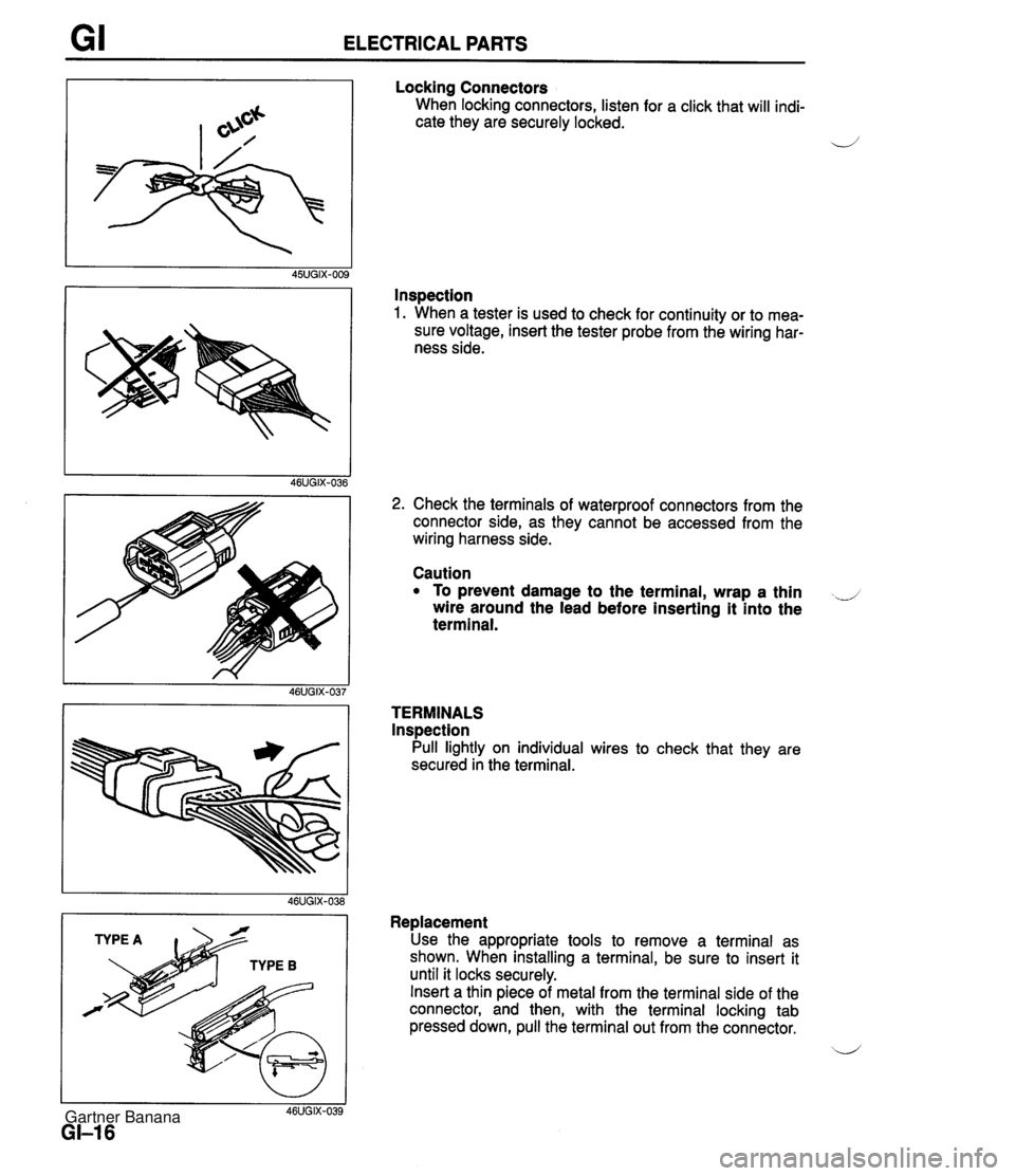
GI ELECTRICAL PARTS Locking Connectors When locking connectors, listen for a click that will indi- cate they are securely locked. 4' Inspection 1. When a tester is used to check for continuity or to mea- sure voltage, insert the tester probe from the wiring har- ness side. I I 46UGIX-039 GI-I 6 2. Check the terminals of waterproof connectors from the connector side, as they cannot be accessed from the wiring harness side. Caution To prevent damage to the terminal, wrap a thin ..J wire around the lead before inserting it into the terminal. TERMINALS lnspection Pull lightly on individual wires to check that they are secured in the terminal. Replacement Use the appropriate tools to remove a terminal as shown. When installing a terminal, be sure to insert it until it locks securely. Insert a thin piece of metal from the terminal side of the connector, and then, with the terminal locking tab pressed down, pull the terminal out from the connector. b' Gartner Banana
Page 40 of 1708

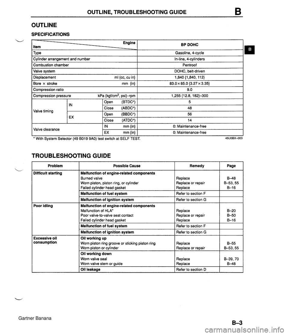
OUTLINE, TROUBLESHOOTING GUIDE OUTLINE SPECIFICATIONS Engine Item Tv~e BP DOHC Gasoline, 4-cvcle . . I -, Dis~lacement ml kc. cu inl I 1.840 (1.840. 11 2) I Cylinder arrangement and number Combustion chamber Valve system Bore x stroke mm {in) I 83.0 x 85.0 (3.27 x 3.35) I In-line, 4-cylinders Pentroof DOHC, belt-driven Com~ression ratio I 9.0 I Compression pressure kPa (kgf/cm2, psi)-rpm .- . 1 open (BTDCO) 1,255 {I 2.8, 182)-300 5 Valve timing TROUBLESHOOTING GUIDE tX Valve clearance Problem .. . -. . Difficult starting ' With System Selector (49 B019 9AO) test switch at SELF TEST. 45uo~x-003 Close (ATDCO) IN mm {in) EX mm {in) Poor idling Close (ABDCO) Open (BBDCO) 14 0: Maintenance-free 0: Maintenance-free Excessive oil consumption 48 56 Possible Cause Malfunction of engine-related components Burned valve Worn piston, piston ring, or cylinder Failed cylinder head gasket Malfunction of fuel system Malfunction of ignition system Malfunction of engine-related components Malfunction of HLA' Poor valve-to-valve seat contact Failed cvlinder head aasket Oil leakage I Refer to section D I I Remedy Malfunction of fuel system Malfunction of ignition system Oil working up Worn piston ring groove or sticking piston ring Worn piston or cylinder Oil working down Worn valve seal Worn valve stem or guide Page Replace Replace or repair Replace Refer to section F Refer to section G Replace Replace or repair Re~lace 8-48 B-53,55 B-1 6 B-20 B-50 B-1 6 Refer to section F Refer to section G Replace Replace or repair Replace Replace B-55 B-53,55 B-39,70 8-48 Gartner Banana
Page 451 of 1708

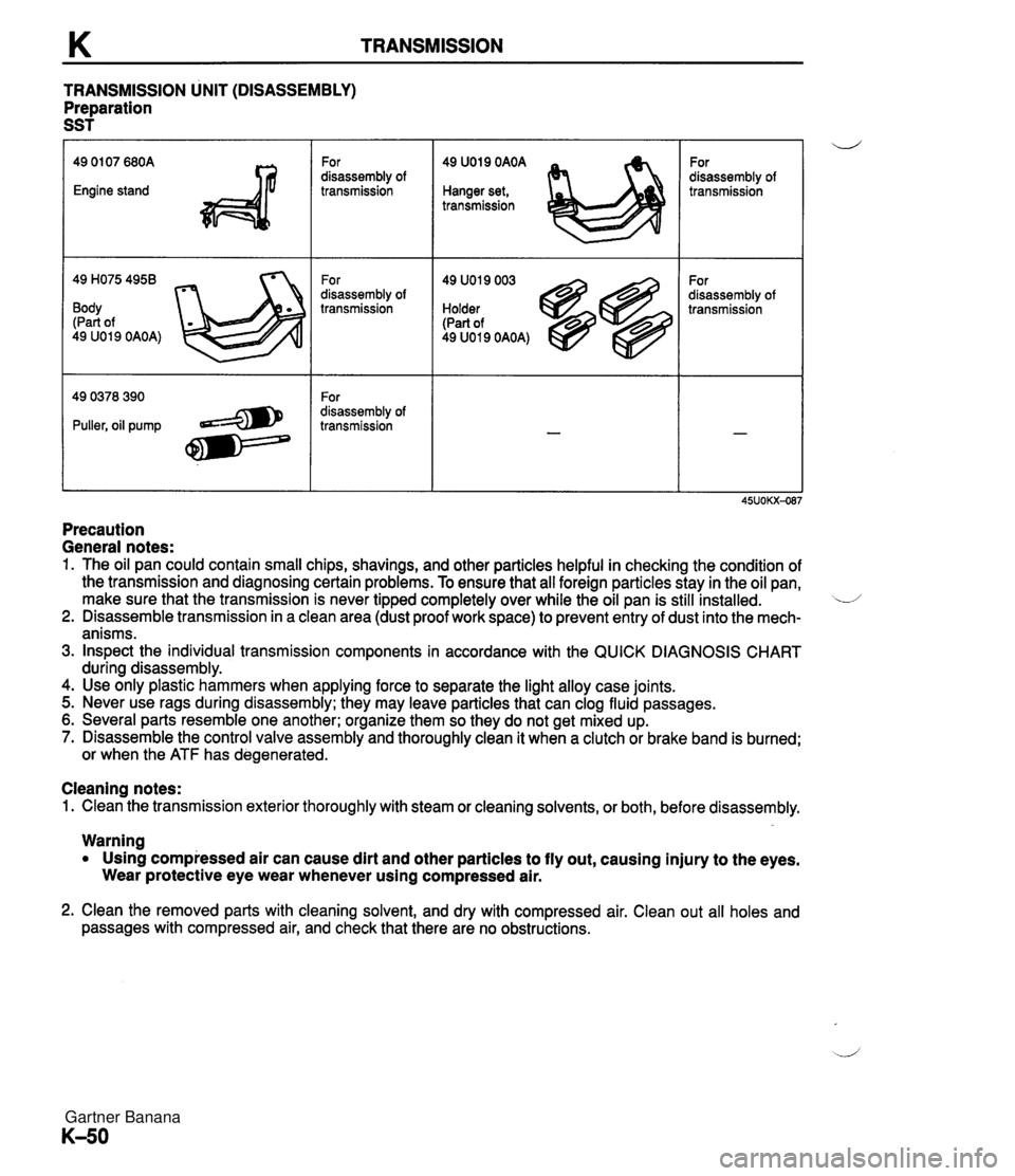
TRANSMISSION TRANSMISSION UNIT (DISASSEMBLY) Preparation SST 49 H075 4958 Body (Part of 49 U019 OAOA) For disassembly of transmission For disassembly of transmission For disassembly of transmission 49 U019 OAOA Hanger set, transmission 49 U019 003 Holder (Part of 49 U019 OAOA) For disassembly of transmission For disassembly of transmission Precaution General notes: 1. The oil pan could contain small chips, shavings, and other particles helpful in checking the condition of the transmission and diagnosing certain problems. To ensure that all foreign particles stay in the oil pan, make sure that the transmission is never tipped completely over while the oil pan is still installed. L/ 2. Disassemble transmission in a clean area (dust proof work space) to prevent entry of dust into the mech- anisms. 3. Inspect the individual transmission components in accordance with the QUICK DIAGNOSIS CHART during disassembly. 4. Use only plastic hammers when applying force to separate the light alloy case joints. 5. Never use rags during disassembly; they may leave particles that can clog fluid passages. 6. Several parts resemble one another; organize them so they do not get mixed up. 7. Disassemble the control valve assembly and thoroughly clean it when a clutch or brake band is burned; or when the ATF has degenerated. Cleaning notes: 1. Clean the transmission exterior thoroughly with steam or cleaning solvents, or both, before disassembly. Warning Using compressed air can cause dirt and other particles to fly out, causing injury to the eyes. Wear protective eye wear whenever using compressed air. 2. Clean the removed parts with cleaning solvent, and dry with compressed air. Clean out all holes and passages with compressed air, and check that there are no obstructions. Gartner Banana
Page 957 of 1708

T AUDIO TYPE 2 AM.FM RADIO UNIT AUTO MEMORY CD EJECT CD SLOT I DISC SET LIGHT- VOLUME CLOCK - / BLANCE BASS - VOLO BA D J I I I I TREBLE ILLUMINATION ONIOFF TAPE SLOT I TREBLE ILLUMINATION ONIOFF I TAPE SLOT DOLBY ALC (AUTO LEVEL CONTROLLER) ROOF MODE ALC ONIOFF BODYSONIC VOLUME ALC INDICATOR LIGHT MUTE 1 FADER MANUAUSEEK - TUNE FAST FOWARDI REWIND - TAPE EJECT PLAY/REVERSE STEREO WIDE I ALC ON + - PW AUTO LEVEL CONTROLLER ONlOFF Gartner Banana
Page 964 of 1708

AUDIO Clock The clock can be adjusted during radio, tape, or CD play. I Name I Illustration Clock button (clock display) ALC (Auto level controller) Name 1 Illustration ALCJbodysonic volume control knob I Mute button Roof mode button I Stereo-wide button Operation Press button to display present radio frequency or operation mode If power supply to unit is broken (burnt fuse or disconnected battery), clock setup will be canceled When clock button is pushed for 2 seconds, clock display flashes. At this point, press H button to advance hours and M button to advance minutes Press clock button again to return to normal display If clock button is pressed again while clock display is flashing and time has not been adjusted (that is, H and M buttons have not been pressed), min- utes will be set at :00. If time before adjustment showed 30-59 minutes, time will be set at next hour For example, Operation Press knob to turn ALC on or off 1. At ON, ALC adjusts sound corresponding to vehicle speed; ALC indica- tor light turns on 2. To adjust seat vibration, turn knob to right or left Right -t Seat vibration increases Left + Seat vibration decreases Turn knob right or left to transfer sound Right -+ Door speakers Left -t Headrest speakers Press button to lower overall volume by 10dB Press button to switch between roof-open mode and roof-closed mode; sound quality is adjusted depending on whether roof is opened or closed Press button to turn stereo-wide function on or off At ON, stereo-wide mode improves sound quality Gartner Banana
Page 1110 of 1708

TD TECHNICAL DATA A. MEASUREMENTS I Item I Measurements I B. ENGINE Overall length mm {in) Overall width mm (in) Overall height mm {in) Wheelbase mm {in) 3,948 (1 55.4) 1,676 i65.9) 1,224 I48.2) 2,266 I89.2) 1,410 (55.5) 1,428 (56.2) Tread - ltem Tvoe u Front mm (in) Rear mm {in) BP DOHC Gasoline. 4-cvcle . In-line, 4-cylinders Pentroof DOHC, belt-driven 16 valves 83.0 x 85.0 {3.27 x 3.35) 1,840 (1,840, 11 2) 9.0 1,255 {I 2.8, 1823-300 883 (9.0, 1281-300 196 {2.0, 28) s. Cylinder arrangement and number Combustion chamber Valve system Bore x Stroke mm {in] Total piston displacement ml {cc, cu in) Compression ratio Valve timing Compression pressure kPa (kgflcm2. psil-r~m I Valve and valve auide I Standard Minimum Maximum difference between each cvlinder - - IN openz (BTDCO) Close (ABDCO) Open (BBDCO) EX close (ATDC") Valve clearance mm {in) Cylinder head 5 48 56 14 IN 133.8-1 34.0 i5.268-5.275) 0.1 0 {0.004) max. 0.10 {0.004) max. 0.02G0.066 {0.0010-0,0025) 0.18 {0.0071) Height mm (in) Distortion mm {in) Grinding mm {in) - 0: Maintenance-free Cylinder head-to-HLA clearance mm (in} Valve head diameter mm Iin) Valve head margin thickness mm {in} Valve face angle I Valve seat 1 u Standard Maximum Valve length mm {in) EX IN EX IN EX IN EX Standard Minimum Standard Minimum IN EX IN EX 5.99--6.03 iO.2359--0.2374) 0.005--0.060 (0.0002-0.0023) 0.01 b0.065 (0.0004-0,0025) 0.20 {0.008} 18.3-1 8.9 {0.7214.744) 18.3-1 8.9 (0.721-0.744) Guide inner diameter mm (in) 0: Maintenance-free 32.9-33.1 {I .296--1.303) 27.85-28.15 {I .097-1 .I 08) 0.9 {0.035) 1 .O (0.039) 45" 45" 101.89 {4.0114} 100.39 {3.9524) 101.99 (4.0153) 100.49 (3,9563) 5.970-5.985 {0.2351-0.2356) 5.96G5.980 l0.2349-0.2354) Valve stem diameter mm {in) Valve stem-to-guide clearance mm (in) Guide projection (Height "A) mm {in) Seat angle IN EX Maximum IN EX IN 45" EX 45" Gartner Banana
Page 1273 of 1708

CONSTRUCTION BODY COMPONENTS .................................................. 24 ................................................... RUST-PROOF STEEL 28 HIGH-STRENGTH STEEL .......................................... 32 Gartner Banana
Page 1278 of 1708

CONSTRUCTION 4 RUST-PROOF STEEL STRUCTURAL VIEW Gartner Banana
Page 1279 of 1708

No. @ I @ I Light lid I I I I I Front wheel apron assy 1 Part Name Bumper bracket @I I Crossmember No. 1 1 8 1 Dash panel assy No. @ 0 @ @I I @ 1 Front wheel apron panel I Part Name Front frame, upper rear Apron reinforcement Dash panel assy Cowl panel front @ @ -1 .............. Both side rust-proof treated steel k!-1 .............. One side rust-proof treated steel (Reverse side only) @ @ @ Front frame rear Stabilizer bracket Front frame Front floor side pan Front frame, upper front @ 0 Front fender panel Torque box @ Shroud panel assy Gartner Banana
Page 1281 of 1708

CONSTRUCTION @ I Trunk lid I @ I Splash protector No. @I I Rear deck member Part Name @ @ I @ I Light housing No. Rear end panel Rear deck panel @ I Floor center pan Part Name @ I @ / Rear fender panel @ @I @ I Crossmember No. 3 Seal plate Quarter panel Floor side panel I @ I Rear fender, lower @ Fuel filler lid @ @ 1 Floor side plate I I I I @ 1 Side sill B, inner Crossmember No. 4 Tank floor pan assy @ @ 1 Bumper bracket @ @ Trunk floor assy @ @ I Q / Front header, upper Door body Side sill, outer @ Floor side panel Rear side frame -1 .............. Both side rust-proof treated steel .............. One side rust-proof treated steel (Reverse side only) Side sill reinforcement Striker reinforcement Side sill C, inner @ @ 0 @ Side panel, inner Wheel inner house Beltline reinforcement Corner junction @ @ @ Side sill A, inner Hinge pillar, outer Cowl side panel Gartner Banana