run flat MAZDA MX-5 1994 Workshop Manual
[x] Cancel search | Manufacturer: MAZDA, Model Year: 1994, Model line: MX-5, Model: MAZDA MX-5 1994Pages: 1708, PDF Size: 82.34 MB
Page 164 of 1708

TROUBLESHOOTING GUIDE DIAGNOSTIC INDEX Cranks normally but will not start (No com- Engine cranks at normal speed but shows no sign of bustion) I #firingN I F-17 I No. 1 TROUBLESHOOTING ITEM Will not crank or cranks slowly -- -- Cranks normally but will not start (Partial combustion) -When engine is cold Cranks normally but will not start (Partial combustion) - After warm-up Cranks normally but hard to start - Always Cranks normally but hard to start - When engine is cold - Engine cranks at normal speed but shows partial com- bustion and will not continue to run Engine cranks at normal speed but shows partial com- bustion and will not continue to run after running and hot soaked Engine cranks at normal speed but requires excessive cranking time (more than 5 sec.) before starting Same condition as No.5 when engine is cold Restarts OK after warm-up 8 DESCRIPTION Refer to Engine Electrical System Low idle speed1Rough idle - Before warm- UP Low idle speed/Rough idle -After warm-up PAGE SECTION G Cranks normally but hard to start - After warm-up Rough idle - Always Engine speed low or engine vibrates excessively at idle during warm-up Engine runs normally at idle during warm-up but vi- brates excessively after warm-up High idle speed - After warm-up Low idle speed - When NC, PIS, or EIL ON l5 1 Engine stalls at idle - Always Engine starts normally but vibrates excessively and stalls at idle in every condition I F40 1 13 14 Same condition as No.5 after running and hot soaked Starts normally when cold Engine vibrates excessively at idle in every condition Engine idle excessive for operation mode Engine speed decreases at idle when NC, PIS, or EIL is ON 18 1 Engine stalls during start-up 1 Engine unexpectedly stops running while starting I F-45 F-26 F-27 F-34 F-36 Rough idle just after starting Idle moves up and down 16 17 l9 1 Engine stalls on deceleration I Engine unexpectedly stops running while decelerating or after deceleration Engine starts normally but vibrates excessively only just after starting Engine speed up and down periodically at idle Engine stalls at idle - Before warm-up Engine stalls at idle - After warm-up Engine stalls at idle -When AIC, PIS, or EIL running at idle when 1 20 1 ON I F-50 1 F-37 F-38 I I . . I 21 1 Engine stalls suddenly (Intermittent) I Engine intermittently stops running I F-52 Engine starts normally but vibrates excessively and stalls at idle before warm-up Engine runs normally at idle during warm-up but be- comes rouclh and stalls after warm-up F-43 F-44 24 1 Lack of power Performance is poor under load Maximum speed re- 1 duced I F-57 I Hesitates/Stumbles on acceleration Surges while cruising I I I 25 / Poor acceleration I Performance is poor while accelerating 1 F-61 I Flat spot occurs just after accelerator is depressed or mild jerking occurs during acceleration Unexpected, usually repetitive change in engine speed Knocking F-53 F-55 Runs rough on deceleration1Afterburn Abnormal combustion accompanied by audible "ping- ing" noise I F-67 I Engine runs rough while decelerating and abnormal combustion in exhaust system 1 30 1 High oil consumption I Oil consumption excessive I F-70 1 F-65 28 1 Fuel odor 29 / Exhaust sulfur smell 1 31 1 Poor fuel economy I Fuel economy unsatisfactory I F-71 I Gasoline odor in cabin Exhaust gas smells abnormal (rotten egg smell) F-69 F-70 Gartner Banana
Page 730 of 1708

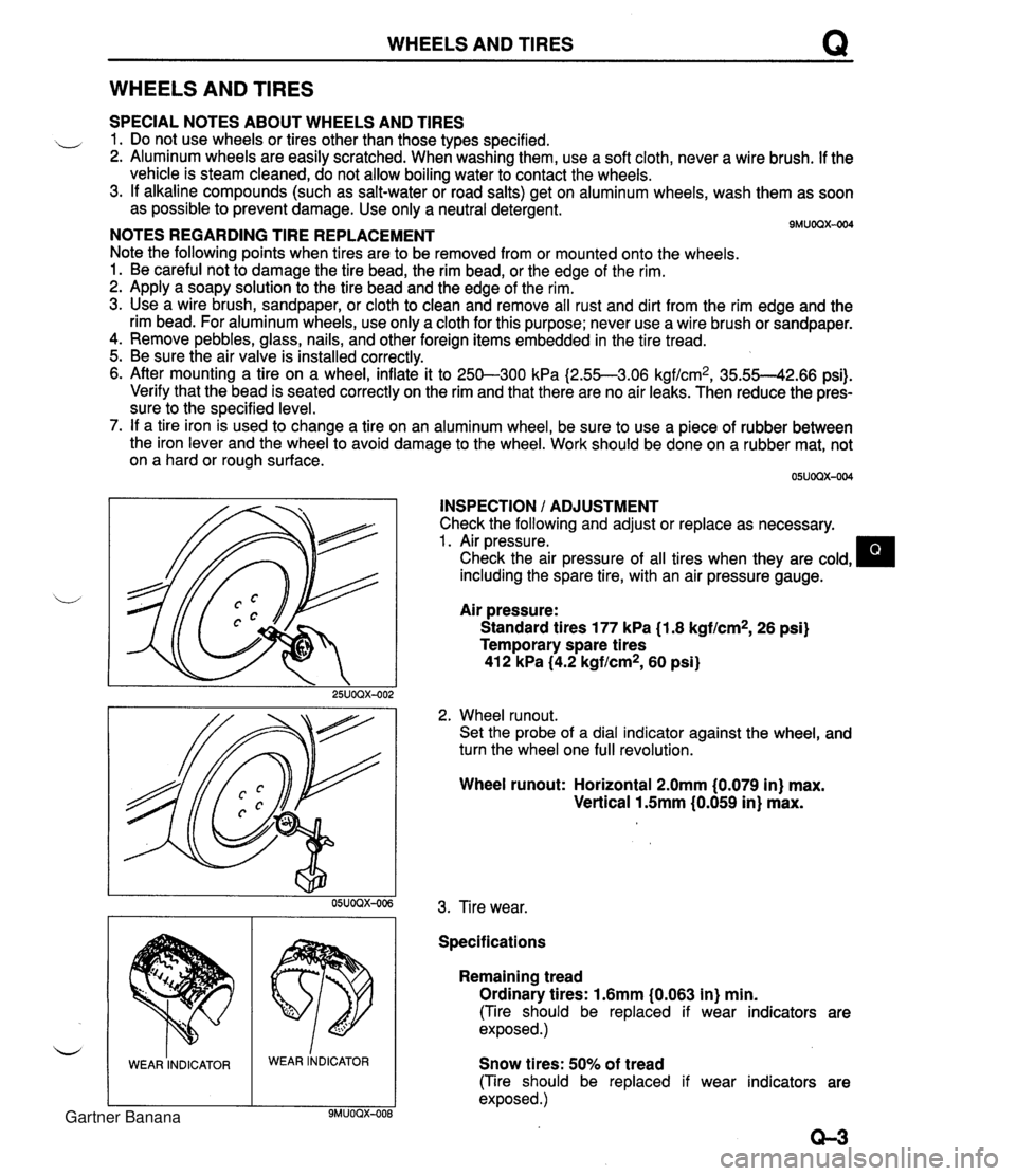
WHEELS AND TIRES Q WHEELS AND TIRES SPECIAL NOTES ABOUT WHEELS AND TIRES ,, 1. Do not use wheels or tires other than those types specified. 2. Aluminum wheels are easily scratched. When washing them, use a soft cloth, never a wire brush. If the vehicle is steam cleaned, do not allow boiling water to contact the wheels. 3. If alkaline compounds (such as salt-water or road salts) get on aluminum wheels, wash them as soon as possible to prevent damage. Use only a neutral detergent. - - 9MUOQX-004 NOTES REGARDING TIRE REPLACEMENT Note the following points when tires are to be removed from or mounted onto the wheels. 1. Be careful not to damage the tire bead, the rim bead, or the edge of the rim. 2. Apply a soapy solution to the tire bead and the edge of the rim. 3. Use a wire brush, sandpaper, or cloth to clean and remove all rust and dirt from the rim edge and the rim bead. For aluminum wheels, use only a cloth for this purpose; never use a wire brush or sandpaper. 4. Remove pebbles, glass, nails, and other foreign items embedded in the tire tread. 5. Be sure the air valve is installed correctly. 6. After mounting a tire on a wheel, inflate it to 250-300 kPa I2.55--3.06 kgf/cm2, 35.55--42.66 psi). Verify that the bead is seated correctly on the rim and that there are no air leaks. Then reduce the pres- sure to the specified level. 7. If a tire iron is used to change a tire on an aluminum wheel, be sure to use a piece of rubber between the iron lever and the wheel to avoid damage to the wheel. Work should be done on a rubber mat, not on a hard or rough surface. INSPECTION / ADJUSTMENT Check the following and adjust or replace as necessary. 1. Air pressure. Check the air pressure of all tires when they are cold, including the spare tire, with an air pressure gauge. u Air pressure: Standard tires 177 kPa (1.8 kgf/cm2, 26 psi) Temporary spare tires 412 kPa (4.2 kgf/cm2, 60 psi) 2. Wheel runout. Set the probe of a dial indicator against the wheel, and turn the wheel one full revolution. WEAR INDICATOR Wheel runout: Horizontal 2.0mm (0.079 in) max. Vertical 1.5mm (0.059 in) max. WEAR lNDICAToR 3. Tire wear. Specifications Remaining tread Ordinary tires: 1.6mm (0.063 in) min. (Tire should be replaced if wear indicators are exposed.) Snow tires: 50% of tread (Tire should be replaced if wear indicators are exposed .) Gartner Banana
Page 738 of 1708

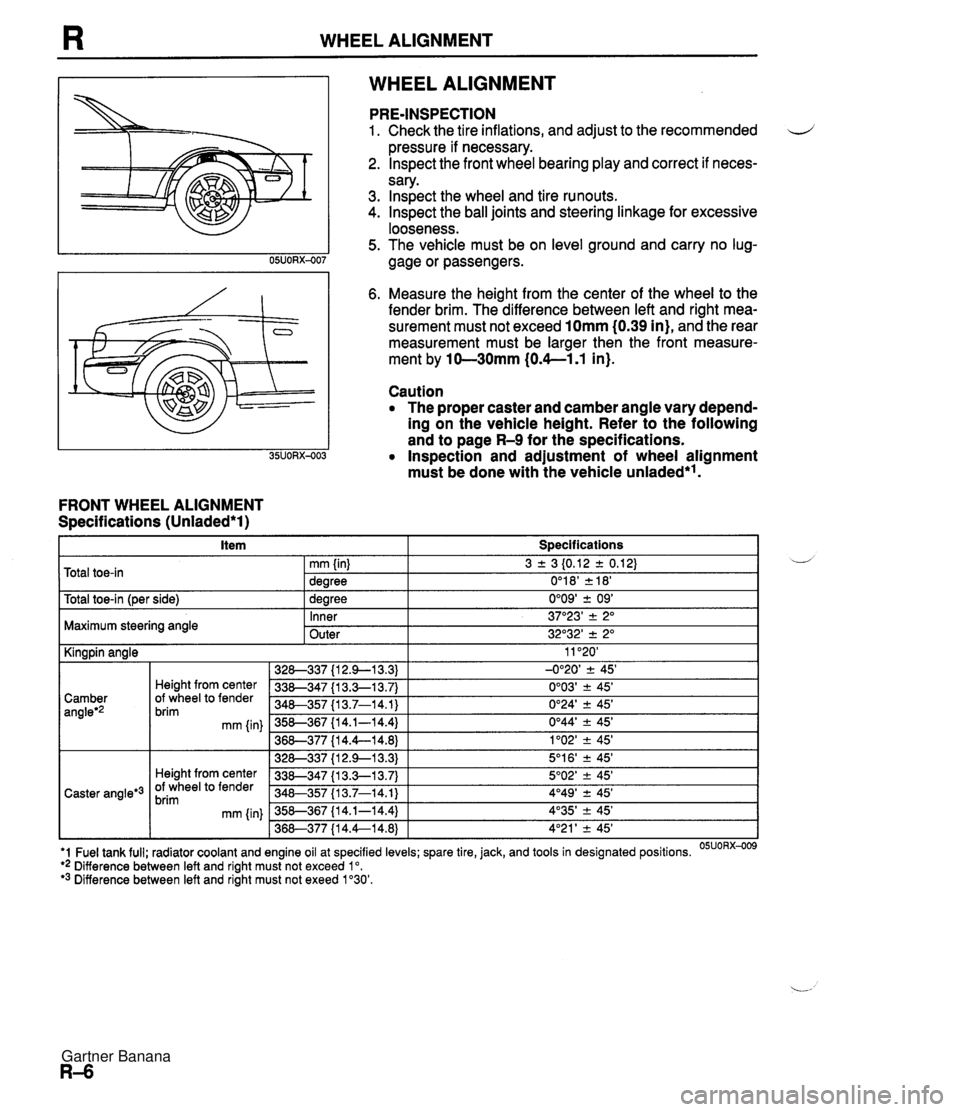
WHEEL ALIGNMENT WHEEL ALIGNMENT FRONT WHEEL ALIGNMENT Specifications (Unladed*l) PRE-INSPECTION 1. Check the tire inflations, and adjust to the recommended d pressure if necessary. 2. lnspect the front wheel bearing play and correct if neces- sary. 3. lnspect the wheel and tire runouts. 4. Inspect the ball joints and steering linkage for excessive looseness. 5. The vehicle must be on level ground and carry no lug- gage or passengers. 6. Measure the height from the center of the wheel to the fender brim. The difference between left and right mea- surement must not exceed 10mm (0.39 in), and the rear measurement must be larger then the front measure- ment by 10-30mm (0.4--1.1 in). Caution The proper caster and camber angle vary depend- ing on the vehicle height. Refer to the following and to page R-9 for the specifications. Inspection and adjustment of wheel alignment must be done with the vehicle unladed*'. . . I Y -- t~otal toe-in l~er side) I 1 dearee 0'09' + 09' I Total toe-in 3 2 3 I0.12 2 0.12) 0'1 8' 2 18' mm (in) dearee Maximum steering angle U - Inner Outer 11 '20' -0°20' 2 45' 0'03' ? 45' 0'24' 2 45' 0°44' -+ 45' 1'02' -+ 45' 5'1 6' ? 45' 5O02' -+ 45' 4O49' 2 45' 4'35' -+ 45' 4'21 ' -+ 45' I Kingpin angle 37"23' -+ 2" 32O32' 2 2" '1 Fuel tank full; radiator coolant and engine oil at specified levels; spare tire, jack, and tools in designated positions. OSUORX-009 ** Difference between left and right must not exceed lo. '3 Difference between left and right must not exeed 1'30'. 328-337 {I 2.9-1 3.3) 338-347 {I 3.3-1 3.7) 340-357 I13.7-14.1) 358-367 {I 4.1-14.4) 36&377 {I 4.4--14.8) 328-337 {I 2.9--13.3) 338-347 {I 3.3-1 3.7) 348-357 113.7-14.1) 358-367 {I 4.1-14.4) 368-377 {I 4.4--14.8) Camber angleg2 Caster angle*3 Height from center Of wheel to fender brim mm {in) Height from center Of wheel to fender brim mm (in) Gartner Banana
Page 918 of 1708

LIGHTING SYSTEM T Symptom: Daytime running lights (DRL) do not illuminate. (Turn signals function normally.) DRL operate with engine running and following switches are off: Headlight switch Turn signal switch (Selected turn signal light flashes, other light remains illumi- nated) Hazard warning switch Parking brake switch (Parking brake released) Step 1 1. Position the vehicle on a flat surface and block the wheels to prevent vehicle movement. 2. Turn the ignition switch to ON. 3. Measure the voltage at the following terminal wires of the DRL control unit. 4. If correct, replace the DRL control unit. B+: Battery positive voltage Step 2 1. Disconnect the parking brake switch connector. 2. Check for continuity between the terminal of the switch and a body ground. Terminal J (L) u Connected to WIPER 20A fuse I(B) B (R) C (WIR) Parking brake lever Pulled one notch Continuity Yes Released Test condition Constant GND Parking brake switch Headlight switch No I 3. If not as specified, adjust or replace the parking brake switch. 4. If correct, repair wiring harness. (DRL control unit - Parking brake switch) Specification B+ Constant Parking brake released Headlight switch off Action Repair wiring harness (WIPER 20A - DRL control unit) Other B+ Other Repair wiring harness (DRL control unit - GND) Go to Step 2 Go to Step 3 Gartner Banana
Page 1309 of 1708

PANEL REPLACEMENT L INSTALLATION Before installing new parts, measure the rear side frame dimensions to verify that they are as specified. After installing new parts, check the fit with associating parts. Turn down the tank floor to the original position after welding the cut-and-join location of the trunk floor and flattening it with a disc grinder. - Plug-weld the trunk floor, tank floor, and crossmember (No. 4). Weld a washer (PART NO. 99952 2240A) at the rear crossmember installing bolt (two points). Gartner Banana
Page 1700 of 1708

ALPHABETICAL INDEX *** ENGLISH **% NUT,DECK LOCK------------ 2- Jli NUT.EXPANSION------------ 2-K7 PANEL( PANEL( PANEL ( PANEL ( PANEL ( PANEL( PANEL( PANEL 1 PANEL 1 PANEL, PANEL 1 PANEL, PANEL, PANEL PIPE,FILLER-------------- 1-ti PIPEIFILLER-FmWASHER TANK 2-E PIPE,FUEL-MAIN----------- 1-5 PIPEIFUEL-RETURN--------- 1 -E PIPE,HEATER UNIT--------- PIPE,OIL----------------- 2-D 1 -K PIPE, OIL LEVEL GAUGE- ---- pIpE,pEDAL--------------- 1 -H 1-c PIPE,RETURN-------------- 1-n 1-C PIPE,SCREEN WASHER------- 2-F , PIPE,SUCTION------------- PIPE,VACUUM-------..------ 1-C 1-E 1 -G PLATE,END---------------- 1-J3 PLATE,HOLDER-BRUSH-------- PLAlE,LOCK--------------- 2- Jl5 1-J11 1 -Mll PLATE,MANUAL------------- 1-K9 FLATE,NUT-TRUNK FLOOR PAN 2-K5 PLATE,OIL BAFFLE--------- 1-E3 PLATE,OIL BAFFLE-CYL. BLK 1-13 Pl.ATE,OIL BAFFLE-EX.----- 1-E3 PLATE,OIL BAFFLE-1N.SIDE- 1-E3 PLATE,PRINT------------..- 2-67 PLATE,RETAINING---------- 1 -C9 1-09 MAGNET------------------- 1 -M7 MANIFOLD,EXHAUST--------- 1 -E4 MANIFOLD,INLET----------- 1 -D4 MAT,FLOOR---------------- 2-N15 MATIREAR END------------- 2-cl6 2-N15 MATITRUNK ROOM----------- 2-C1C MEMBER NO.E(?),CROSS-FLOO 2-L5 MEHBER N0.2(Rl1CROSS-FLOO 2-K5 MEMBER N0.3,CROSS-------- 2 -K5 MEMSER N0.4,CROSS-------- 2-K5 HEMBER(R1,INST. PANEL---- 2- J7 MEMBER ,CRASH PAD--------- 2- J7 NEMBER,CHOSS------------- 1-Fli 1-Kl! 1-L11 NUT,LOCK-CLUTCH HUB------ 1-H6 NUTILOCK-COUNTER SHAFT BR 1-H6 KUT,LQCK-RACK------------ 1-Lli NUT ,MOUNTING- ANTENNA--- - -- 2-El4 NUTISELF LOCK------------ 2-Lli tUT,SIDE PROTECTOR------- 2-C4 NUT,SPRING--..------------ 2-E4 2- I7 NUT,STOPPER-LAMP HINGE--- 2-L3 NUTITOP-CRASH PAD-------- 2-L7 NUTIWIPER LINK----------- 2-El5 PRHEL ;PLATE-MODE CONTROL- 2-El 1 ! 2-N4 i pIpE,VINYL--------------- 1-K7 / PANEL.RAD.SHROUD--------- 2-Dl5 PLATE.SEAL-T PANEL; REAR DECK---------- 2-H5 2..H5 jXATER--------------- 2-6 PANEL,REAR END----------- PANEL, ,ROOF--------------- 1-E .?-ti12 PIPEIA',CYLINDER--------- I -N PARTS K1T.INN.-BKAKE----- 1-F15 PIPEIB'.CYLINDER--------- 1-N .51 PLATE ; SEPARA 1 .- t4 PARTS YIT,INNER---------- PARTS SET---------------.- 1 -E 2- J PARTS SET,ST. WHEEL------ PAsS,OIL----------------- 1-H 1-D PAWL,PARKING------------- 1 -K PEDAL g ARM-------------- 1-G PEDAL,BRAKE-------------- 1-c 1 -L PEDAL,CLUTCH------------- 1-L PIECE,DISTANCE----------- 1-1 1 -n 2-N4 MEMBER ,REAR DECK------ --- 2-H5 METAL SET,CONN.ROD------- 1 -L3 METAL SET,MAIN BRG.------ 1 -L3 METAL SET ,THRUST--------- METER SET---------------- 1 -M3 2-67 METER,FUEL--------------- 2-H7 METER, OIL PRESSURE------- 2-67 METER,TEMP--------------- 2-117 MIRROR(L),DOOH----------- 2-El4 NIRRORCK) ,DOOR----------- 2-€16 MIRROR,INTERIOR---------- 2-El6 2-Flt MODULE,AIR BAG----------- 2-H9 MODULE ,AIR BAG PASSENGER- 2-H9 MODULE ,POWERTRAIN CONTROL 2-Cl? MODULE,PWT.CONTROL------- 2-Cl! MOTOR( L 1, RETRACTABLE HEAD 2-L3 MOTOR(R),RETRACTABLE HEAD 2-L3 MOTOR IFAN-BLOWER UNIT---- 2-F11 HUTOR, WIPER----------- --- 2-H15 MOULn(UP). FRT. WItJDOW----- 2-J3 OIL,COMPRESSOR----------- 2-Kll OPEtiER,FILLER LID-------- 1-K14 OPENER,T/LID 8 F/LID----- ORIFICE------------------ 1-K14 1-F3 ORNAMENT,FRONT----------- 2-14 ORNAMENT,MAKER NAME-REAR- 2-14 ORNANENT,REAR------------ 2-14 ORNAMENT,STEREO---------- 2-MI! ORNAMENT,STEREO-LOWER---- 2-Ml! ORNAMENT,STEREO-UPPER---- OUTLET ,WATER----- ---.----- 2-Hl! 1-E5 PLATE NO. 2(L), SET-F. BUMPE 2-~3 PLATE N0.2(R),SET-F.BUMPE 2-F3 PLATE N0.3,SEAL---------- PLATE SET---------------- 2-111 2-H3 9-72 ! L-A4 PLATECC) SET-TOP FABRIC-- 2-0121 PLATE(FRT1,SET-ROOF PANEL 2-E12, PIN,CtiECKER-------------- 1 -M 2-M PIN,DECK LOCK------------ 2- J PIN,GUIDE----.------------ 1 -G PIN,INTER LOCK----------- 1- J PIN,PIVOT-CLUTCH REL .FORK 1-C PIN,SLIDER--------------- 1-6 PIN,SNAP----------------- 1 -D 1 -G PLATE(L)------.----------- 2-F10 PLATE(L1,CLOSING-QTR PANE 2-35 PLATECL),FROtiT SCUFF----- 2-L15 PLATEtL),HOOK-REAR DECK-- 2-F12 PLATE(L1,KICK-D.TRIM----- 2-F10 PLATE(L1,SEAL------------ 2- I5 PLATE(L),SET-TOP FABRIC-- 2-612 PLATE(L),SIDE-REAR FLOOR- 2-L5 ~LATE(R)----------------- 2-F10 PLATE(R1,CLOSING-QTR PANE 2-H5 PLATE(R1,END------------- 2-65 PLATE(R1,FRONT SCUFF----- 2-L15 PLATE(R),HOOK-REAR DECK-- 2-F12 PLATE