charging MAZDA PROTEGE 1992 Owner's Manual
[x] Cancel search | Manufacturer: MAZDA, Model Year: 1992, Model line: PROTEGE, Model: MAZDA PROTEGE 1992Pages: 1164, PDF Size: 81.9 MB
Page 451 of 1164

CHARGING SYSTEM G
Disassembly / Assembly
1. Disassemble in the order shown in the figure.
2. Inspect all parts and repair or replace as necessary.
3. Assemble in the reverse order of disassembly.
P-105 N.m (9.5-11 m-kg, 61-79 ft.lb)
N-m (cm-kg, in-l
OBUOGX-0
1. Pulley 6. Rectifier
2. Front cover Inspection .,,,..,,,,.....,,.,.,,............. page G-13
3. Rotor 7. Brush holder assembly
Inspection . . . . . . . . . . . . . . . . . . . . . . . . . . . . . . . . . . . page G-12 Inspection
4. Rear bracket (Brush and brush spring) . . . . . . . . . page G-13
5. Stator 8. Bearing
Inspection . . . . . . . . . . . . . . . . . . . . . . . . page G-l 2 Inspection .,.,,...,......,......,............ page G-13
G-l 1
Page 452 of 1164
![MAZDA PROTEGE 1992 Owners Manual G CHARGING SYSTEM
23UOGX-OO!
23UOGX-00
03UOGX-02,
03UOGX-02
Inspection
Rotor
1. Measure the resistance between the slip rings with an
ohmmeter.
Specification: 3.5-4.5Q [at 20°C (66OF)]
2. I MAZDA PROTEGE 1992 Owners Manual G CHARGING SYSTEM
23UOGX-OO!
23UOGX-00
03UOGX-02,
03UOGX-02
Inspection
Rotor
1. Measure the resistance between the slip rings with an
ohmmeter.
Specification: 3.5-4.5Q [at 20°C (66OF)]
2. I](/img/28/57077/w960_57077-451.png)
G CHARGING SYSTEM
23UOGX-OO!
23UOGX-00
03UOGX-02,
03UOGX-02
Inspection
Rotor
1. Measure the resistance between the slip rings with an
ohmmeter.
Specification: 3.5-4.5Q [at 20°C (66OF)]
2. If not within specification, replace the rotor.
3. (1) Check continuity between each slip ring and the core
with an ohmmeter.
(2) Replace the rotor if there is continuity.
4. Check if the slip ring surface is rough. Use fine sandpaper
to repair it if necessary.
Stator
1. Check for continuity between the stator coil leads with an
ohmmeter.
2. Replace the stator it there is no continuity.
3. Check continuity between the stator coil leads and the core
with an ohmmeter.
4. Replace the stator if there is continuity.
G-12
Page 453 of 1164

CHARGING SYSTEM G
L
23UOGX.00
P2 I9
WEAR LIMIT
03UOGX-021
03UOGX-02C
03UOGXz
Rectifier
1. Check continuity of the diodes with an ohmmeter.
Negative
E
B
T
Pl, P2,
P3
Pl, P2, P3
Positive
PI,
P2, P3
E
B
T
Continuity
Yes
No
No
No
Yes
Yes
2. Replace the rectifier if necessary.
Brush
If a brush is worn almost to or beyond the limit, replace the
brushes.
Standard: 21Smm (0.848 in)
Minimum: 8.0mm (0.315 in)
Brush spring
1. Measure the force of the brush spring with a spring pres-
sure gauge.
2. Replace the spring if necessary.
Standard force:
3.1-4.3 N (320-440 g, 11.3-15.5 oz)
Minimum: 1.6-2.4 N (160-240 g, 5.6-8.5 oz)
Note
l Read the spring pressure with the brush tip project-
ing 2mm (0.079 in).
Bearing
1. Check for abnormal noise, looseness, or sticking
2. Replace the bearing(s) if necessary.
G-l 3
Page 454 of 1164
G CHARGING SYSTEM
WATER PUMP 13UOGX-00,
03UOGX-03:
I /I I III
I f 03UOGX-03:
03UOGX-034
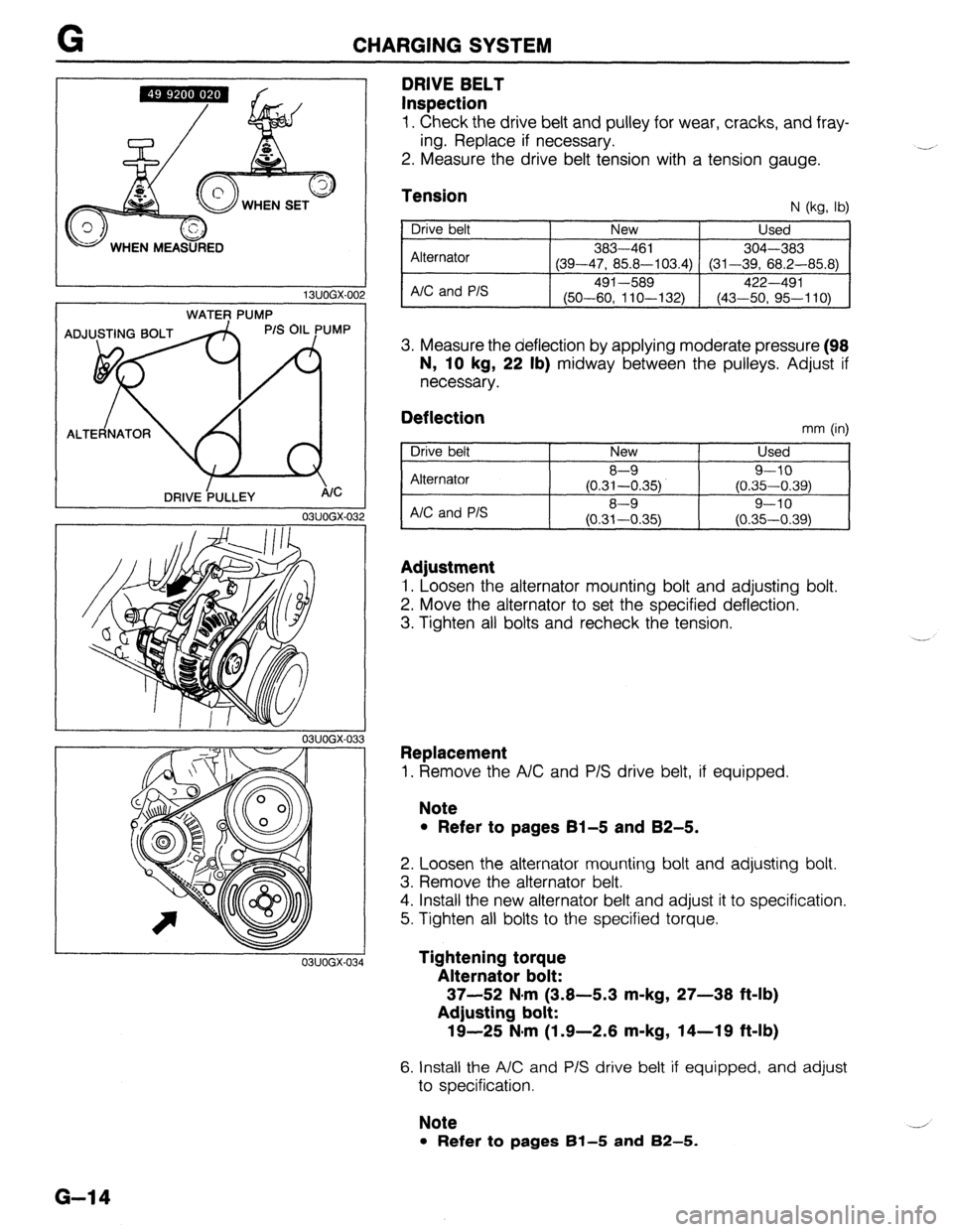
DRIVE BELT
Inspection
1. Check the drive belt and pulley for wear, cracks, and fray-
ing. Replace if necessary.
2. Measure the drive belt tension with a tension gauge. .-A
Tension N (kg, lb)
Drive belt
Alternator
A/C and P/S New Used
383-461
304-303
(39-47, 85.8-103.4) (31-39, 68.2-85.8)
491-589 422-491
(50-60, 11 O-l 32) (43-50, 95-110)
3. Measure the deflection by applying moderate pressure (98
N, 10
kg, 22 lb) midway between the pulleys. Adjust if
necessary.
Deflection mm (in)
Drive belt
Alternator
AIC and P/S New Used
8-9 9-10
(0.31-0.35) (0.35-0.39)
8-9 9-10
(0.31-0.35) (0.35-0.39)
Adjustment
1. Loosen the alternator mounting bolt and adjusting bolt.
2. Move the alternator to set the specified deflection.
3. Tighten all bolts and recheck the tension.
Replacement
1. Remove the A/C and P/S drive belt, if equipped.
Note
l Refer to pages 61-5 and 82-5.
2. Loosen the alternator mounting bolt and adjusting bolt.
3. Remove the alternator belt.
4. Install the new alternator belt and adjust it to specification.
5. Tighten all bolts to the specified torque.
Tightening torque
Alternator bolt:
37-52 N#rn (3.8-5.3 m-kg, 27-38 ft-lb)
Adjusting bolt:
19-25 N-m (1.9-2.6 m-kg, 14-19 ft-lb)
6. Install the A/C and P/S drive belt if equipped, and adjust
to specification.
Note
l Refer to pages 61-5 and 82-5.
G-14
Page 869 of 1164
FUSE AND JOINT BOX
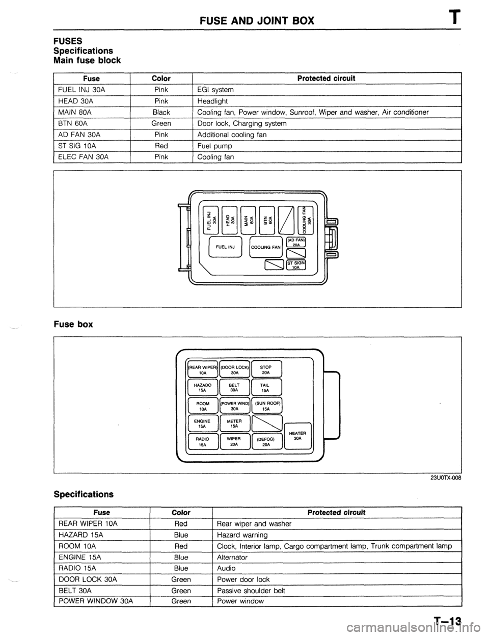
FUSES
Specifications
Main fuse block
Fuse Color
FUEL INJ 30A Pink
HEAD 30A Pink
MAIN 80A Black
BTN 60A Green
AD FAN 30A Pink
ST SIG 10A Red
ELEC FAN 30A Pink Protected circuit
EGI system
Headlight
Cooling fan, Power window, Sunroof, Wiper and washer, Air conditioner
Door lock, Charging system
Additional cooling fan
Fuel pump
Cooling fan
Fuse box
23UOTX-001
Specifications
Fuse
REAR WIPER 10A
HAZARD 15A
ROOM IOA
ENGINE 15A
RADIO 15A
DOOR LOCK 30A
BELT 30A
POWER WINDOW 30A Color
Red
Blue
Red
Blue
Blue
Green
Green
Green Protected circuit
Rear wiper and washer
Hazard warning
Clock, interior lamp, Cargo compartment lamp, Trunk compartment lamp
Alternator
Audio
Power door lock
Passive shoulder belt
Power window
1
T-13
Page 973 of 1164
TROUBLESHOOTING GUIDE U
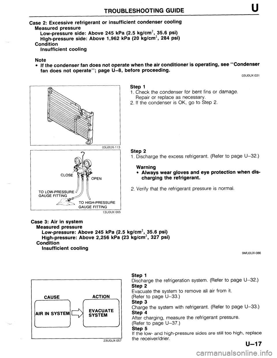
Case 2: Excessive refrigerant or insufficient condenser cooling
Measured pressure
Low-pressure side: Above 245 kPa (2.5 kg/cm2, 35.6 psi)
High-pressure side: Above 1,962 kPa (20 kg/cm2, 284 psi)
Condition
Insufficient cooling
Note
l If the condenser fan does not operate when the air conditioner is operating, see “Condenser
fan does not operate”; page U-8, before proceeding.
TO LOW
GAUGE
H-PRESSURE
GAUGE FITTING
13uoux-00 5 03uoux-031
Step 1
1. Check the condenser for bent fins or damage.
Repair or replace as necessary.
2. If the condenser is OK, go to Step 2.
Step 2
1. Discharge the excess refrigerant. (Refer to page U-32.)
Warning
l Always wear gloves and eye protection when dis-
charging the refrigerant.
2. Verify that the refrigerant pressure is normal.
Case 3: Air in system
Measured pressure
Low-pressure: Above 245 kPa (2.5 kg/cm2, 35.6 psi)
High-pressure: Above 2,256 kPa (23 kg/cm2, 327 psi)
Condition
Insufficient cooling
. . CAUSE ACTION
AIR IN SYSTEM EVACUATE
SYSTEM
9MUOUX-086
Step 1
Discharge the refrigeration system. (Refer to page U-32.)
Step 2
Evacuate the system to remove all air from it.
gFI;;r; page U-33.)
Charge the system with refrigerant. (Refer to page U-33.)
Step 4
After charging, measure the refrigerant pressure.
(Refer to page U-37.)
Step 5
If the low- and high-pressure sides are still too high, replace
I
23UOUX-057 the receiver/drier.
Page 974 of 1164
U TROU6LESHOOTlNG GUIDE
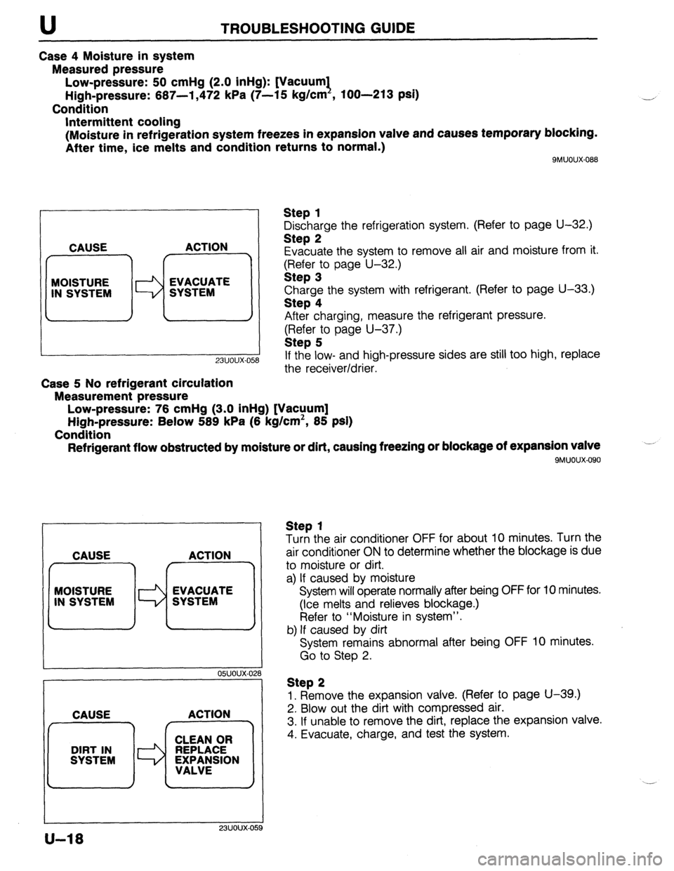
Case 4 Moisture in system
Measured pressure
Low-pressure: 50 cmHg (2.0 inHg): [Vacuum1
High-pressure: 667-l ,472 kPa (7-15 kg/cm , loo-213 psi)
Condition
Intermittent cooling
(Moisture in refrigeration system freezes in expansion valve and causes temporary blocking.
After time, ice melts and condition returns to normal.)
SMUOUX-088
CAUSE ACTION
7 r
MOISTURE
IN SYSTEM WW;MTE
-
23uoux-O!
Case 5 No refrigerant circulation
Measurement pressure
Low-pressure: 76 cmHg (3.0 inHg) [Vacuum]
High-pressure: Below 589 kPa (6 kg/cm’, 85 psi)
Condition
Refrigerant flow obstructed by moisture or dirt, causing freezing or blockage of expansion valve
9MUOUX.090
Step 1
Discharge the refrigeration system, (Refer to page U-32.)
Step 2
Evacuate the system to remove all air and moisture from it.
$?&$r:o page U-32.)
Charge the system with refrigerant. (Refer to page U-33.)
Step 4
After charging, measure the refrigerant pressure.
(Refer to page U-37.)
Step 5
If the low- and high-pressure sides are still too high, replace
the receiver/drier.
CAUSE ACTION
f r^‘---7
MOISTURE
Id EVACUATE
IN SYSTEM SYSTEM
I I
05UOUX-02
CAUSE ACTION
23UOUX-OE
Step 1
Turn the air conditioner OFF for about 10 minutes. Turn the
air conditioner ON to determine whether the blockage is due
to moisture or dirt.
a) If caused by moisture
System will operate normally after being OFF for 10 minutes.
(Ice melts and relieves blockage.)
Refer to “Moisture in system”.
b) If caused by dirt
System remains abnormal after being OFF 10 minutes.
Go to Step 2.
Step 2
1. Remove the expansion valve. (Refer to page U-39.)
2. Blow out the dirt with compressed air.
3. If unable to remove the dirt, replace the expansion valve.
4. Evacuate, charge, and test the system.
U-18
Page 988 of 1164

CHARGING HOSE
CLOSED
CLOSED
23UOUX-061
CHARGING HOSE
CHARGING VALVE CLOSED 0
23UOUX.061
3. Connect high-and low-pressure side charging hoses and
stop valves to the refrigerant system service valves.
23UOUX-062
FREON (REFRIGERANT RECOVERY
ND RECYCLING
CONTAINER
VALVE
Manifold gauge set/Stop valve installation
Caution
l Connect all charging hoses via stop valves to avoid
venting the refrigerant remaining in the hoses into
the atomosphere. _A
l Do not disconnect the stop valve from the charg-
ing hose when there is refrigerant remaining in the
hose.
1. Turn the knob counterclockwise to close the stop valve.
2. Install the stop valve to the end of the charging hose of the
manifold gauge set.
Caution
l Verify that high-and low-pressure side valves of the
manifold gauge set are fully closed before connect-
ing the charging hose and stop valve to the refriger-
ant system service valve.
23UOUX-063 Evacuation/Airtiahtness test
1. Connect the manifold gauge set and stop valves to the
refrigerant system service valves.
2. Connect the center hose of the manifold gauge set to the
vacuum pump inlet.
3. Prepare as follows according to the charging method.
Charging from service container.
Connect the charging hose and service container valve to the
manifold gauge set air purge valve.
I
23UOUX-06
U-32
4
Refrigerant recovery operation.
Remove the refrigerant from the refrigerant system by using
a freon (refrigerant) recovery and recycling system.
Caution
. Never vent the refrigerant into the atomosphere.
l When using a freon recovery and recycling system,
follow the operation instructions provided by the
equipment manufacturer.
_-,
Page 989 of 1164

U
r
I
23UOUX-061
23UOUX-067
23UOUX-061 3
Caution
l Connect the charging hose to the air purge valve
via its tap pin side.
l Do not disconnect the charging hose or the serv-
ice container valve until the charging operation is
completed.
l Do not open the service container valve when not
used.
Charging from freon recovery and recycling system.
Connect the charging hose and stop valve to the manifold
gauge set air purge valve.
23UOUX-065
Caution
l Connect the charging hose to the air purge valve
via its tap pin side.
l Do not disconnect the charging hose or stop valve
until the charging operation is completed.
l Do not open the stop valve when not used.
4. Start the vacuum pump and open the high-and low-pressure
side valves of the manifold gauge set.
5. Start the pump and let it operate for 15 minutes.
6. Check high- and low-pressure side gauge readings. When
both of them are at 750 mmHg or more, close the manifold
gauge set valves.
7. Stop the vacuum pump and wait for about 5 minutes.
8. Verity that the low-pressure side gauge reading does not
change.
9. If the reading changes, retighten the piping connections and
repeat the evacuation operation.
10. If not changed, check for leaks (see below) and charge the
system.
u-33
Page 990 of 1164
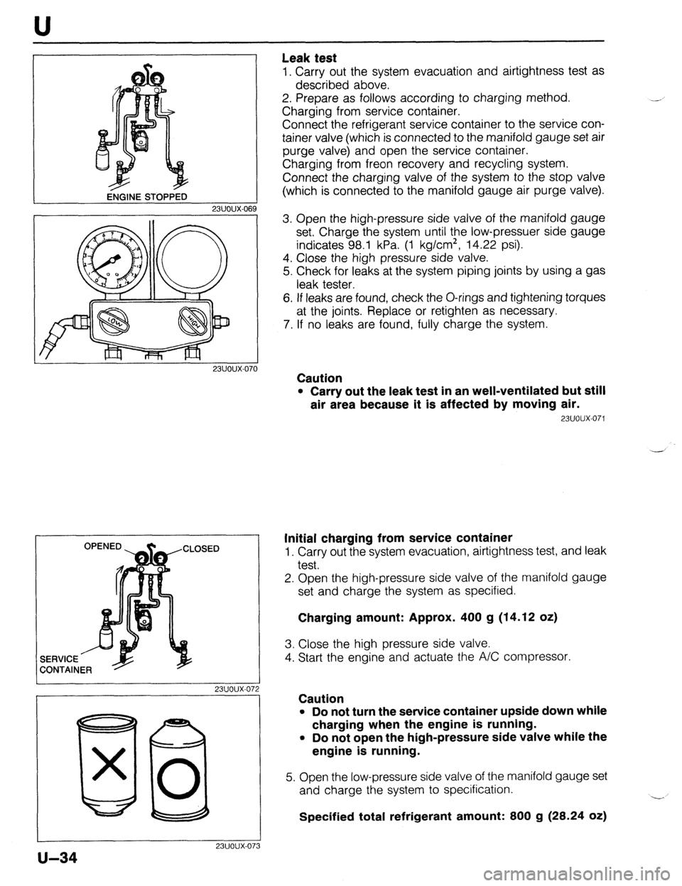
ENGINE sro~i32 U
Leak test
1. Carry out the system evacuation and airtightness test as
described above.
2. Prepare as follows according to charging method.
Charging from service container.
Connect the refrigerant service container to the service con-
tainer valve (which is connected to the manifold gauge set air
purge valve) and open the service container.
Charging from freon recovery and recycling system.
Connect the charging valve of the system to the stop valve
(which is connected to the manifold gauge air purge valve).
23UOUX-06
23UOUX-070
I 23UOUX-072
I
80 x 0
23UOUX-07
u-34
3
3. Open the high-pressure side valve of the manifold gauge
set. Charge the system until the low-pressuer side gauge
indicates 98.1 kPa. (1 kg/cm*, 14.22 psi).
4. Close the high pressure side valve.
5. Check for leaks at the system piping joints by using a gas
leak tester.
6. If leaks are found, check the O-rings and tightening torques
at the joints. Replace or retighten as necessary.
7. If no leaks are found, fully charge the system.
Caution
l Carry out the leak test in an well-ventilated but still
air area because it is affected by moving air.
23UOUX-071
Initial charging from service container
1. Carry out the system evacuation, airtightness test, and leak
test.
2. Open the high-pressure side valve of the manifold gauge
set and charge the system as specified.
Charging amount: Approx. 400 g (14.12 oz)
3. Close the high pressure side valve.
4. Start the engine and actuate the A/C compressor.
Caution
l Do not turn the service container upside down while
charging when the engine is running.
l Do not open the high-pressure side valve while the
engine is running.
5. Open the low-pressure side valve of the manifold gauge set
and charge the system to specification.
Specified total refrigerant amount: 800 g (28.24 oz) -.