change wheel MAZDA PROTEGE 1992 Workshop Manual
[x] Cancel search | Manufacturer: MAZDA, Model Year: 1992, Model line: PROTEGE, Model: MAZDA PROTEGE 1992Pages: 1164, PDF Size: 81.9 MB
Page 703 of 1164

WHEELS AND TIRES
WHEELS AND TIRES
SPECIAL NOTES ABOUT WHEELS AND TIRES
1. Do not use wheels or tires other than the specified types.
2. Aluminum wheels are easily scratched. When washing them, use a soft cloth, never a wire brush. If the
vehicle is steam cleaned, do not allow boiling water to contact the wheels.
3. If alkaline compounds (such as saltwater or road salts) get on aluminum wheels, wash them as soon as
possible to prevent damage. Use only a neutral detergent.
9MUOQX-004
NOTES REGARDING TIRE REPLACEMENT
Note the following points when tires are to be removed from or mounted onto the wheels.
1. Be careful not to damage the tire bead, the rim bead, or the edge of the rim.
2. Use a wire brush, sandpaper, or cloth to clean and remove all rust and dirt from the rim edge and the
rim bead.
3. When cleaning aluminum wheels, use a soft cloth, never a wire brush or sandpaper.
4. Remove any pebbles, glass, nails, and other foreign items embedded in the tire tread.
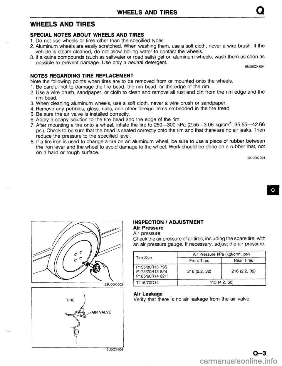
5. Be sure the air valve is installed correctly.
6. Apply a soapy solution to the tire bead and the edge of the rim.
7. After mounting a tire onto a wheel, inflate the tire to 250-300 kPa (2.55-3.06 kg/cm2, 35.55-42.66
psi). Check to be sure that the bead is seated correctly onto the rim and that there are no air leaks. Then
reduce the pressure to the specified level.
8. If a tire iron is used to change a tire on an aluminum wheel, be sure to use a piece of rubber between
the iron lever and the wheel to avoid damage to the wheel. Work should be done on a rubber mat, not
on a hard or rough surface.
03UOQX-004
23UOOX-003
TIRE
I
AIR VALVE
INSPECTION / ADJUSTMENT
Air Pressure
Air pressure
Check the air pressure of all tires, including the spare tire, with
an air pressure gauge. If necessary, adjust the air pressure.
Tire Size Air Pressure kPa (kgf/cm2, psi)
Front Tires Rear Tires
P155180R13 79s
PI 75/70R13 82s 216 (2.2, 32) 216 (2.2, 32)
P185/60R14 82H
1115/70D14 415 (4.2, 60)
Air Leakage
Verify that there is no air leakage from the air valve.
I I 13UOOX-008
Q-3
Page 714 of 1164

WHEEL ALIGNMENT
Camber and Caster
1, Jack up the front of the vehicle and support it with safety
stands.
2. Remove the mounting block nuts.
-
1 BUORX-01
23UORX-0;
3. Push the mounting block downward, and turn it to the
desired position.
Direction indicator
position
A
: Difference from standard position
Camber angle Caster angle
+14’ +14’
+29’ O0
+14’ -14’
4. Install and tighten the mounting nuts to the specified torque.
Tightening torque:
29-40 Nnrn (3.0-4.1 m-kg, 22-30 ft-lb)
Total toe-in
1. Loosen the left and right tie rod locknuts, then turn the tie
rods equally.
Caution
l The left and right tie rods are both right threaded,
so, to increase the toe-in, turn the right tie rod to-
ward the front of the vehicle and the left tie rod
equally toward the rear.
l One turn of the tie rod (both sides) changes the toe-
in by about 6mm (0.24 in).
2. Tighten the tie rod locknuts.
Tightening torque:
34-50 N-m (3.5-5.1 m-kg, 25-37 ft-lb)
Page 715 of 1164

WHEEL ALIGNMENT
REAR WHEEL ALIGNMENT
Specifications
kern Specifications
Total mm (in) 2 f 3 (0.08 f 0.12)
Wheel alignment
(*‘Unladen) Rear toe-in
degree 0.2O f 0.3O
Camber angle -0020’ f 45’
*I Fuel tank full; radiator coolant and engine oil at specified level; and spare tire, jack, and tools in designated positions.
13UORX-012
Adjustment
Total toe-in
1. Loosen the lateral link locknuts.
2. Turn the lateral link adjustment link to adjust.
Note
l One turn of the link changes 11.3mm (0.44 in).
3. Tighten the lateral link locknuts to the specified torque.
Tightening torque:
55-64 N,m (5.6-6.5 m-kg, 41-47 ft-lb)
R-9