distributor MAZDA PROTEGE 1992 Owner's Guide
[x] Cancel search | Manufacturer: MAZDA, Model Year: 1992, Model line: PROTEGE, Model: MAZDA PROTEGE 1992Pages: 1164, PDF Size: 81.9 MB
Page 443 of 1164

OUTLINE G
OUTLINE
SPECIFICATIONS
Item EnginelTransaxle
‘-2, B6 SOHC BP SOHC BP DOHC
MTX 1 ATX MTX ( ATX
Voltage v 1 12
I
3attery
Dark current*’ Type and capacity
(20-hour rate)
mA 55D23L (60AH) 55D23L (60AH)
Max. 20.0
L\lternator
Starter
Type AC
output V-A 12-65
Regulator type Transistorized (built-in IC regulator)
Regulated voltage V 14.1-14.7
Brush length Standard 21.5 (0.846)
mm (in) Minimum 8.0 (0.315)
Drive belt deflection
New
98 N (10 kg, 22 lb)
mm (in) Used 8-Q (0.31-0.35)
Q-10 (0.35-0.39)
Type
I Direct Direct
I Coaxial
Direct Coaxial
reduction reduction I
output V-kW 12-0.95 12-0.95 12-1.4
12-0.95 12-1.4
Brush length Standard 17 (0.67) 17 (0.67) 17.5 (0.69) 17 (0.67)
17.5 (0.69)
mm (in) Minimum 11.5 (0.453) 11.5 (0.453) 10.0 (0.39) 11.5 (0.453) 10.0 (0.39)
Distributor
Ignition timing BTDC
(TEN terminal of diagnosis connector grounded) Electronic spark advance (photo diode)
6O--8O 4O-6O Q”-1 1 o
Ignition coil
Spark plug Resistance
(at 20% [68OF]) Primary
coil winding 0.81-O.QQg
Secondary
coil winding IO-16 kg
BKR5E-11 BKR5Ell BKR5Ell
NGK
BKR6E-11 BKRGEl 1 BKRGEli
BKR7Ell
Type NIPPON-
DENSON Kl GPR-Ul l
K20PRU 11 KIGPR-Ull
K20PR-Ul l KIGPR-Ull
K20PRUll
K22PR-Ul l
I Plua aao mm (in) I 1.0-l .l (0.039-0.043)
Firing order
’ Dark current is the constant flow of current while the ignition switch is OFF.
(i.e. engine control unit, audio, etc.) l-3-4-2
23lJOGX-00
G-3
Page 455 of 1164

IGNITION SYSTEM G
IGNITION SYSTEM
PREPARATION
SST
49 NO18 001
Adapter Harness
CIRCUIT DIAGRAM
ECU
T
IGNITION SWITCH
,
I
DISTRIBUTOR
7
1 ZL BATTERY
IGNITER
03UOGX-03t
G-15
Page 456 of 1164

G IGNITION SYSTEM
TROUBLESHOOTING
iTEP
INSPECTION
ACTION
1
Check if MIL illuminates when engine is running Yes Check for malfunction code number
and perform troubleshooting (TEN ter-
minal grounded) c7 Section F
No Go to next step
2 Drsconnect high-tension lead from distributor and
Yes
check for strong blue spark while cranking en-
l Check distributor cap and rotor v page G-22
gine * Check high-tension lead
KP page G-19 c7 page G-17
+ Ignition system normal
No
Go to next step
3 Check if resistance of ignition coil is OK
Yes
Go to next step ~7
page G-19
Specification (at 20°C [66”9):
Primary coil winding: 0.81-0.99Q No
Replace ignition coil
Secondary coil winding: IO-16 kQ
-i
Check if resistance of high-tension leads is OK Yes Go to next step
D= page G-17
Specification: 16 kQ per 1 m (3.28 ft)
No Replace high-tension lead
5 Check if igniter is OK
m- page G-23 Yes
Replace ECU
No
Replace igniter
03UOGX-03
G-16
Page 457 of 1164

IGNITION SYSTEM G
r
03UOGX-03
SOHC
LOCK BOLTS
DOHC
A LOCK BOLTS I 03UOGX-0’
03UOGX-C
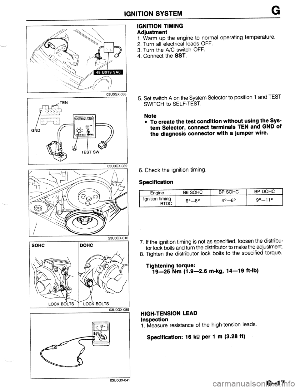
IGNITION TIMING
Adjustment
1. Warm UD the enaine to normal operating temperature.
2. Turn all ‘electricarloads OFF.
3. Turn the A/C switch OFF.
4. Connect the
SST.
5. Set switch A on the System Selector to position
SWITCH to SELF-TEST. 1 and TEST
Note
l To create the test condition without using the Sys-
tem Selector, connect terminals TEN and GND of
the diagnosis connector with a jumper wlre.
6. Check the ignition timing.
Specification
Engine
Ignition timing
BTDC B6 SOHC BP SOHC
60-8O 4O-6O
BP DOHC
9°-110
7. If the ignition timing is not as specified, loosen the distribu-
tor lock bolts and turn the distributor to make the adjustment.
8. Tighten the distributor lock bolts to the specified torque.
Tightening torque:
19-25 N-m (1.9-2.6 m-kg, 14-19 ft-lb)
HIGH-TENSION LEAD
Inspection
1. Measure resistance of the high-tension leads.
Specification: 16 kg per 1 m (3.26 ft)
G-l 7
Page 459 of 1164

IGNITION SYSTEM . . . ._,
03UOGX-04
Lszl /
P
0 V
- 23UOGX-OC
03UOGX-048
03UOGX-04
03UOGX-0%
IGNITION COIL
Inspection
Spark test
1. Disconnect the high-tension lead from the distributor.
2. Hold it with insulated pliers 5-l
Omm (0.20-0.39 in) from
a ground.
3. Crank the engine and verify that a strong blue spark is
visible.
4. If there is no spark, disconnect the connector from the igni-
tion coil and check for voltage at the positive (+) terminal
of the connector with the ignition switch in the ON position.
Specification: Battery voltage
5. If there is no voltage, check the main fuse, ignition switch,
and wire harness.
Primary coil winding
1. Use an ohmmeter and measure resistance of the primary
coil winding. If not within specification, replace the coil.
Prlmary coil resistance: 0.81-0.99112 (at 2O*C [88*F])
Secondary coil winding
1. Use an ohmmeter and measure resistance of the secon-
dary coil winding. If not within specification replace the coil.
Secondary coil resistance: lo-18 kQ (at 20°C [68*F])
Insulation of case
1. Use a 500V megger tester to measure the insulation resis-
tance between each terminal and the case.
Speclficatlon: 10 MS1 min.
G-19
Page 460 of 1164

G IGNITION SYSTEM
I
03UOGX~051
03UOGX-052
DISTRIBUTOR
Spark Test
1. Disconnect the high-tension lead from each spark plug.
2. Hold each insulator with pliers
5-10mm (0.20-0.39 in)
from a ground.
3. Crank the engine and verify that a strong blue spark is
visible.
Electronic Advance Inspection
1. Verify that the ignition timing advances with engine ac-
celeration.
G-20 ._... -~
._ _
Page 461 of 1164

IGNITION SYSTEM G
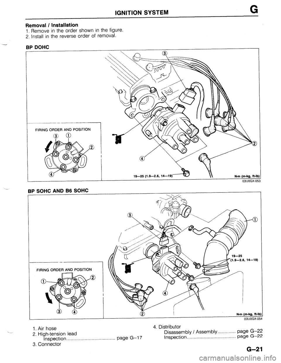
Removal I Installation
1. Remove in the order shown in the figure.
2. Install in the reverse order of removal.
RP I’lClHC
FIRING ORDER AND POSITION
19-25 (1.9-2.6,
14-19)
N-m (m-kg, R-lb
03UOGX-053
(1.9-2.6, 14-19)
FIRING ORDER AND POSITION
1. Air hose 4. Distributor
2. High-tension lead Disassembly / Assembly. . . . . . . . . . . . . page G-22
Inspection ,..*....,.........,..,............. page G-l 7 Inspection.. . ,.....,,.,..,........,,.,....... page G-22
3. Connector
G-21
Page 463 of 1164

IGNITION SYSTEM G
03UOGX-05
03UOGX-05t 3
03UOGX-059
03UOGX-06
VOLTMETER 0
03UOGX-06
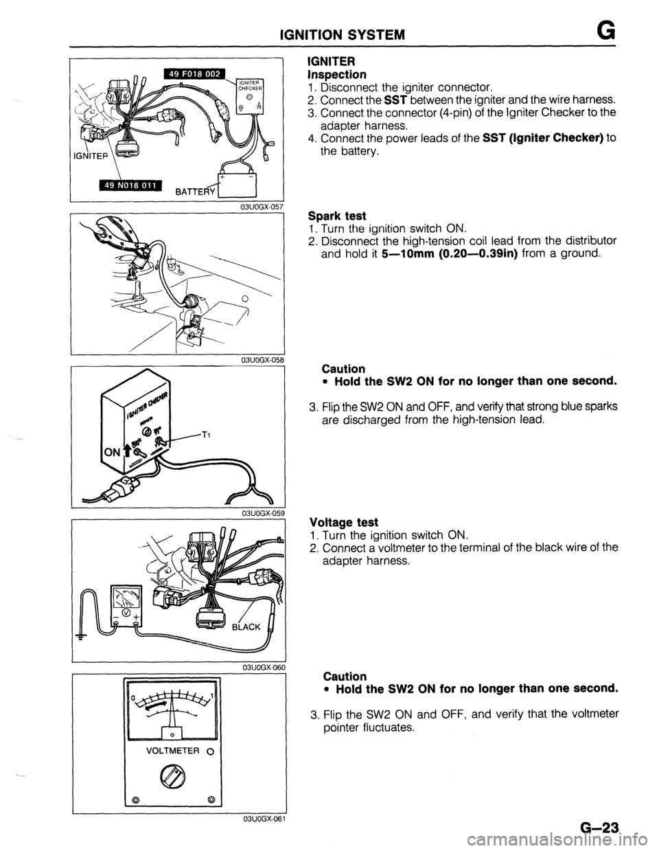
IGNITER
Inspection
1. Disconnect the igniter connector.
2. Connect the
SST between the igniter and the wire harness.
3. Connect the connector (4-pin) of the Igniter Checker to the
adapter harness.
4. Connect the power leads of the
SST (Igniter Checker) to
the battery.
Spark test
1. Turn the ignition switch ON.
2. Disconnect the high-tension coil lead from the distributor
and hold it
5--10mm (0.20-0.39in) from a ground.
Caution
l Hold the SW2 ON for no longer than one second.
3. Flip the SW2 ON and OFF, and verify that strong blue sparks
are discharged from the high-tension lead.
Voltage test
1. Turn the ignition switch ON.
2. Connect a voltmeter to the terminal of the black wire of the
adapter harness.
Caution
l Hold the SW2 ON for no longer than one second.
3. Flip the SW2 ON and OFF, and verify that the voltmeter
pointer fluctuates.
G-23
Page 1024 of 1164

TD TECHNICAL DATA
G. ENGINE ELECTRICAL SYSTEM
3attery Dark
current*’
Alternator 86 SOHC BP SOHC
I BP DOHC
MTX 1 ATX 1 MTX 1 ATX
Voltage V 12
Type and capacity (20-hour rate) 55D23L (60AH) 1 55D23L (60AH)
mA Max. 20.0
Type A.C
output V-A 12-65
Regulator type Transistorized (built-in IC regulator)
Regulated voltage V 14.1-14.7
Brush length Standard 21.5 (0.846)
mm (in) Minimum 8.0 (0.315)
Drive belt deflection
New 8-Q (0.31-0.35)
;riL’F,i Used Q-10 (0.35-0.39)
Coaxial
Type Direct Direct Coaxial
reduction Direct
reductior
Starter output V-kW 12-0.85 12-0.95 12-1.4 12-0.95 12-1.4
Brush length Standard 17 (0.67) 17 (0.67) 17.5 (0.69) 17 (0.67) 17.5 (0.69
mm (in) Minimum 11.5 (0.453) 11.5 (0.453) 10.0 (0.39) 11.5 (0.453) 10.0 (0.39
Distributor Electronic spark advance (photo diode)
Ignition timing BTDC
(TEN terminal of diagnosis connector grounded) 6O-8O 4O-6O 9”-11 O
Ignition coil Resistance Primary coil winding 0.81 -O.QQg
(at 20% [68OF]) Secondary coil winding lo-16 kg
SK&E-1 1 BKR5E-11
NGK
BKRGE-11 BKRGE-11
BKR7E-11
Spark plug Type
NIPPONDENSO KlGPR-Ull
K20PRUll KlGPR-Ull
K20PRUll
K22PRUll *:
. Plug gap
Firing order mm (in) 1.0-l .l (0.039-0.043)
l-3-4-2
---
’ Dark current is the constant flow of current while the ignition switch IS UFF.
(i.e engine control unit, audio, etc.) ..-
._*
T&l 0
Page 1049 of 1164

PARTS INDEX
‘I
A
ACCELERATOR CABLE ............................. F-l 14
ACCELERATOR PEDAL ............................. F-l 14
AIR CONDITIONER ...................................... u-30
A/C RELAY.. ........................................... U-56
A/C SWITCH ...........................................
U-57
COMPRESSOR.. ..................................... U-41
CONDENSER.. ....................................... U-53
CONDENSER FAN ................................. u-57
CONDENSER FAN RELAY .................... U-56
COOLING UNIT ..................................... U-38
MAGNETIC CLUTCH ............................. u-51
RECEIVER/DRIER .................................. U-52
REFRIGERANT PRESSURE SWITCH.. .. U-55
AIR FLOW METER ..................................... F-l 68
AIR VALVE.. ................................................ F-l 16
ALTERNATOR .............................................. G-10
ANTENNA FEEDER
AUDIO
....... .......................................................................................... T-i;
AUTOMATIC TRANSAXLE ............................. K-l
2-4 BRAKE BAND ................................ K-l 97
3-4 CLUTCH.. ....................................... K-l 87
ACCUMULATORS ................................ K-l 67
ATF ....................................................... K-135
ATF THERMOSENSOR ........................ K-142
BEARING COVER ASSEMBLY ............ K-208
CLUTCH ASSEMBLY ........................... K-l 72
CONTROL VALVE BODY.. .....
K-21 0,224,234
DIFFERENTIAL ..................................... K-236
DRIVE PLATE.. ..................................... K-267
EC-AT CONTROL UNIT ....................... K-144
HOLD SWITCH ..................................... K-140
HYDRAULIC CIRCUIT .......................... K-278
IDLER GEAR ........................................ K-203
INHIBITOR SWITCH ............................. K-l 41
LOW AND REVERSE BRAKE .............. K-192
MAIN CONTROL VALVE BODY .......... K-220
OIL COOLER.. ...................................... K-265
OIL PUMP ............................................
K-169
OIL SEAL ..............................................
K-209
ONE-WAY CLUTCH 2
CARRIER HUB ASSEMBLY ............... K-185
OUTPUT GEAR .................................... K-206
P RANGE SWITCH.. ............................. K-271
PREMAIN CONTROL VALVE BODY .a. K-218
PULSE GENERATOR ........................... K-142
SELECTOR LEVER ............................... K-272
SHIFT MECHANISM ............................. K-269
SHIFT-LOCK ACTUATOR
..................... K-271
SMALL SUN GEAR AND
ONE-WAY CLUTCH 1 ........................ K-l 82
SOLENOID VALVE.. ............................. K-l 43
SPEEDSENSOR .................................. K-l 43
THROTTLE CABLE .............................. K-l 37
TORQlJE CONVERTER.. ...................... K-l 66
TRANSAXLE UNIT. ......... K-149,153,246,261 UPPER CONTROL VALVE BODY.. ..... K-215
BACK-UP LIGHT SWITCH..
..........................
BATTERY T;4;
- .......................................................
BLOWER UNIT ............................................
U-23
BRAKE FLUID.. .............................................. P-8
BRAKE MASTER CYLINDER. ...................... P-10
BRAKE PEDAL ...............................................
P-8
C
CALIPER .................................................. P-21,26
CARGO COMPARTMENT LAMP ................. T-54
CENTRAL PROCESSING UNIT..
.................. T-55
CHARCOAL CANISTER ............................. F-l 41
CHECK VALVE (TWO-WAY) .......................
CHECK-AND-CUT VALVE - .......................... ;-;b$
CIRCUIT OPENING RELAY.. ...................... F-129
CLUTCH COVER ......................................... H-l 7
CLUTCH DISC ............................................. H-l 7
CLUTCH FLUID ............................................. H-4
CLUTCH MASTER CYLINDER.. .................... H-7
CLUTCH PEDAL ............................................ H-5
CLUTCH RELEASE CYLINDER..
................. H-12
CLUTCH SWITCH (MTX) ............................ F-l 72
COMBINATION SWITCH .............................. T-23
COWL GRILLE ............................................. S-53
CRUISE CONTROL UNIT.. ...................... T-78,85
D
DASHBOARD ............................................... S-94
DASHPOT ................................................... F-l 42
DISTRIBUTOR .............................................. G-20
DOOR LOCK TIMER UNIT ........................... T-17
DOOR MIRROR ............................................ S-54
REMOTE CONTROL MIRROR ............... S-56
REMOTE CONTROL MIRROR SWITCH. S-55
DOOR SPEAKER .......................................... T-98
DRIVE SHAFT.. ....................................... M-l 7,21
DRL RELAY.. ................................................ T-18
DRL RESISTOR ............................................ T-46
DUAL PROPORTIONING VALVE..
............... P-l 6
DYNAMIC CHAMBER ................................ F-l 12
E
ELECTRIC COOLING FAN SYSTEM ........... E-13
ENGINE (B6 & BP SOHC) ........................... Bl-2
CAMSHAFT ..........................................
Bl-58
CAMSHAFT PULLEY ...........................
Bl-65
CONNECTING ROD ............................. 81-63
PI-I