distributor MAZDA PROTEGE 1992 User Guide
[x] Cancel search | Manufacturer: MAZDA, Model Year: 1992, Model line: PROTEGE, Model: MAZDA PROTEGE 1992Pages: 1164, PDF Size: 81.9 MB
Page 271 of 1164

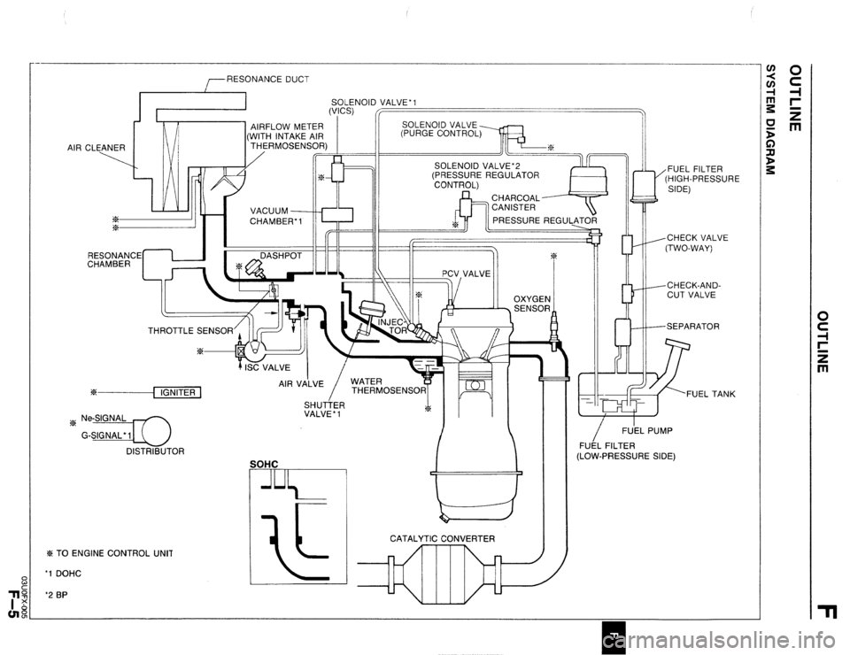
RESONANCE DUCT
SOLENOID VALVE’1
AIR CLEANER
ix
%
4.L VACUUM
CHAMBER-1
RESONANCE
CHAMBER DASHPOT
w/r) --CHECK VALVE
(TWO-WAY)
I II 14 J--CHECK-AND-
II l/%x II/ II _ \,\, _.-.,I CUT VALVE
TH
?z% ---{ IGNITER 1
~ Ne-SIGNAL 1/
G-SIGNAL’IU
DISTRIBUTOR AIR VA’LVE
/ WATER
THERMOSENSOR
SHUTTER 7
VALVE * 1 s%
SOHC
% TO ENGINE CONTROL UNIT
‘1 DOHC
‘2 BP
I CATALYTIC CONVERTER /
FU’EL PUMP
FUEL FILTER
(LOW-PRESSURE SIDE)
Page 277 of 1164

EGI EC-AT eENGINE CONTROL SYSTEM &i EC-AT CONTROL SYSTEM(2/3)
DISTRI8UTOR -W/R IEM) ::
MAIN RELAY [FUEL INJI
(SECTION B-2d
I-4)
F-2)
@
t-01 ENGINE CONTROL UNIT (EM) 82-09 DISTRIBUTOR (EM)
X L/O x G/O
!-17 INJECTOR N0,4(INJ) 82-18 WATER THERMOS:NSyFB2-25 SOLENOID VALVE
(vIcs) (INJ)
Page 280 of 1164

F OUTLINE
A comparison of the new and previous models is as follows.
Engine Control Unit Terminal Relation Ship Chart
Connected to
Headlight switch Terminal
Connected to Terminal
New Previous New Previou
1H IU
Water thermosensor 2E 2Q
Diagnosis connector
(TEN terminal) / II 1 IK 1 1 Throttle sensor
Rear window defroster switch
I I 21 2K
Ground (California)
Main relay (Canada)
A/C relay
Vehicle speed sensor
P/S pressure switch
A/C switch
Blower control switch 1K 2H
IL 1J
1M --
1N 1P
10 IQ
1P 1s Distributor
(G-signal) [DOHC]
Intake air thermosensor
Solenoid valve
(Purge control)
Ground (Injector)
Ground (Output)
Ground (CPU) 2J 2G
2K 2P
20 2x
___
Stoplight switch 1Q 10
Ground (Input)
1 I I 1 ! 3D ! 2D
Cruise control main switch
1 lS / - II8cRalnardega,y
Throttle sensor
(Idle switch)
Distributor
(Ne-signal) 1T 1N
2A 2E
2B 20
2C 2N Solenoid valve
(VICS)
--.-- I_-
Solenoid valve
(Pressure regulator) [BP] 31 2s
-- -_
3M 2T
Airflow meter
Oxygen sensor
-
Fan switch 1 2D 1 IR 1 1 lniector (Nos. 2, 4) I 3v I 2v
23UOFX-01 I
F-l 4
Page 282 of 1164

F OUTLINE
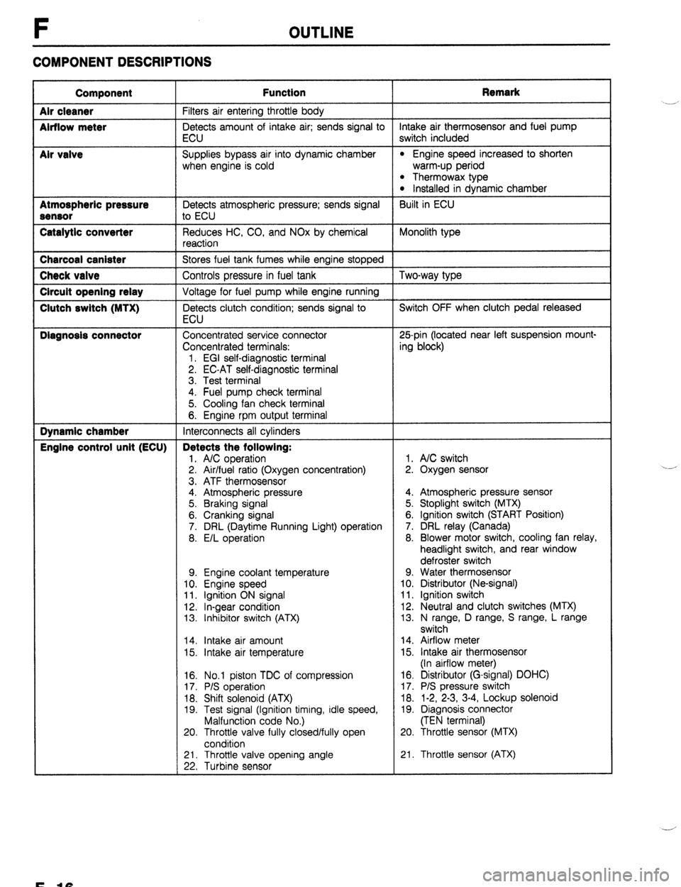
COMPONENT DESCRIPTIONS
Component
Air cleaner
Airflow meter
Mr valve
Atmospheric pressure
Sensor
Catalytic converter Function Remark
Filters air entering throttle body
Detects amount of intake air; sends signal to intake air thermosensor and fuel pump
ECU switch included
Supplies bypass air into dynamic chamber
l Engine speed increased to shorten
when engine is cold warm-up period
l Thermowax type l Installed in dynamic chamber
Detects atmospheric pressure; sends signal Built in ECU
to ECU
Reduces HC, CO, and NOx by chemical Monolith type
reaction Charcoal canister
Stores fuel tank fumes while engine stopped Check valve
Controls pressure in fuel tank Two-way type Circuit opening relay
Voltage for fuel pump while engine running Clutch switch (MTX)
Detects clutch condition; sends signal to Switch OFF when clutch pedal released
ECU Diagnosis connector
Concentrated service connector 25pin (located near left suspension mount-
Concentrated terminals: ing block)
1. EGI self-diagnostic terminal
2. EC-AT self-diagnostic terminal
3. Test terminal
4. Fuel pump check terminal
5. Cooling fan check terminal
6. Engine rpm output terminal Dynamic chamber
Interconnects all cylinders Engine control unit (ECU) Detects the following:
1. A/C operation 1. A/C switch
2. Air/fuel ratio (Oxygen concentration) 2. Oxygen sensor
3. ATF thermosensor
4. Atmospheric pressure 4. Atmospheric pressure sensor
5. Braking signal 5. Stoplight switch (MTX)
6. Cranking signal 6. Ignition switch (START Position)
7. DRL (Daytime Running Light) operation 7. DRL relay (Canada)
8. E/L operation 8. Blower motor switch, cooling fan relay,
headlight switch, and rear window
defroster switch
9. Engine coolant temperature 9. Water thermosensor
10. Engine speed 10. Distributor (Ne-signal)
11. Ignition ON signal 11. Ignition switch
12. In-gear condition 12. Neutral and clutch switches (MTX)
13. Inhibitor switch (ATX) 13. N range, D range, S range, L range
switch
14. Intake air amount 14. Airflow meter
15. Intake air temperature 15. Intake air thermosensor
(In airflow meter)
16. No.1 piston TDC of compression
17. P/S operation
18. Shift solenoid (ATX)
19. Test signal (Ignition timing, idle speed,
Malfunction code No.)
20. Throttle valve fully closed/fully open
condition 16. Distributor (G-signal) DOHC)
17. P/S pressure switch
18. 1-2, 2-3, 3-4, Lockup solenoid
19. Diagnosis connector
(TEN terminal)
20. Throttle sensor (MTX)
21. Throttle valve opening angle
22. Turbine sensor 21. Throttle sensor (ATX) .__r
F-10
Page 308 of 1164
![MAZDA PROTEGE 1992 User Guide F TROUBLESHOOTING GUIDE
8 ROUGH IDLE/ENGINE STALLS AT IDLE - ALWAYS
bESCRIP- l Engine starts normally but stalls or vibrates excessively at idle in every condition
‘ION TROUBLESHOOTING HINTS]
D MAZDA PROTEGE 1992 User Guide F TROUBLESHOOTING GUIDE
8 ROUGH IDLE/ENGINE STALLS AT IDLE - ALWAYS
bESCRIP- l Engine starts normally but stalls or vibrates excessively at idle in every condition
‘ION TROUBLESHOOTING HINTS]
D](/img/28/57077/w960_57077-307.png)
F TROUBLESHOOTING GUIDE
8 ROUGH IDLE/ENGINE STALLS AT IDLE - ALWAYS
bESCRIP- l Engine starts normally but stalls or vibrates excessively at idle in every condition
‘ION TROUBLESHOOTING HINTS]
D Air/Fuel mixture too lean @ Incorrect idle speed
l Air leakage l Idle speed misadjustment l Fuel injection control malfunction l Idle speed control malfunction
*Low fuel line pressure @ One or more spark plugs not firing
3 One or more injectors clogged or not operating @ Low engine compression
3 Low intake air amount @ Airflow meter stuck INSPECTION
1
1
2
3
4
5
6
- Check if “00” is displayed on Self-Diagnosis
Checker with ignition switch ON w page F-82
SYSTEM2ELECT: 1
M v’SELECT SW: A TEST
Check if ECU terminal voltages are OK
MTX...Especially 2D, 20 and 2Q
ATX... Especially 2B, 2E and 3D CT page F-150
Disconnect high-tension lead at idle and check if
engine speed decreases equally at each cylinder
Check for injector operating sound at idle
Check if battery voltage exists at injector connec-
tor (W/R) wire
Check if strong blue spark is visible at discon-
nected high-tension lead
, Yes No Service Code No. displayed
Check for cause (Refer to specified
:heck sequence) “88” flashes
Check ECU terminal IF voltage CT page F-150
Specification: Battery voltage
(Ignition switch ON)
3 If OK, replace ECU w page F-149 3 If not OK, check wiring between
ECU and Self-Diaanosis Checker Yes
Go to next step No
Check for cause Yes
Go to Step 8 No
Go to next step
Go to Step 6
Go to Step 5 Yes
No
Yes
No
Yes
No I-
30 to next step w page F-83
0 page F-151
Check if injector resistance is OK c7 page F-131
Resistance: Approx. 12-l 852
c3 If OK, check wiring between ECU
and injector
c3 If not OK, replace injector w page F-131
Check wiring between ECU and injector
Go to next step
Check high-tension lead w page G-17
Q If OK, check distributor cap and
rotor w page G-22
c3 If not OK, replace high-tension lead
F-42
Page 313 of 1164

TROUBLESHOOTING GUIDE F
Fuel line pressure:
265-314 kPa (2.7-3.2 kg/cm’, 36-46 psi)
(Vacuum hose to pressure regulator Ine pressure while pinching
d If fuel line pressure quickly in-
creases, check pressure regulator w page F-129
* If fuel line pressure gradually in-
If not clogged, check fuel pump
maximum pressure w page F-126
Ignition timing (BTDC)
l BP DOHC : go-1 1 o l BP SOHC : 4”-6O
Resistance: 12-l 60
eck wiring between ECU
Engine compression (Minimum):
l BP SOHC :
634 kPa (6.5 kg/cm2, 121 psi)900 rpm
check distributor cap and
23UOFX-02
F-47
Page 319 of 1164

TROUBLESHOOTING GUIDE F
No Replace airflow meter
9
Check for injector operating sound at idle Yes Go to Step 11
No Go to next Step
10 Check if battery voltage exists at injector connec- Yes Check if injector resistance is OK CT page F-131
tor (W/R) wire Resistance: 12-l 6fi
c3 If OK, check wiring between ECU
and injector
c3 If not OK, replace injector CT page F-131
No
Check wiring between ECU and injector
11 Check if strong blue spark is visible at discon-
Yes Go to next step
netted high-tension lead
No Check high-tension lead
+ If OK, check distributor cap and
rotor w page G-22
* If not OK, replace high-tension lead
12
Check if spark plugs are OK Yes Check for correct engine compression CT page Bl-10
w page G-16 82-10
Compression (Minimum):
. BP SOHC
834 kPa (8.5 kg/cm2, 121 psi)300 rpm
BON BUILDUP l BP DOHC
883 kPa (9.0 kg/cm*, 128 psi)-300 rpm
l.O-l.lmm ’ B6 DAMAGE AND 932 kPa (9.5 kg/cm’, 135 psi)-300 rpm DETERIORATION
c3 If OK, go to next step
c13 If not OK, check for cause CT page Bl-10
B2-10
No
Clean or replace w page G-18
13
Check for injector leakage Yes Replace injector CT page F-131
w page F-132
No Go
to next step
14 Try known good ECU and check if condition im-
proves cc7 page F-149
23UOFX-030
F-53
Page 320 of 1164

F TROUBLESHOOTING GUIDE
15
ENGINE STALLS ON DECELERATION
DESCRIP-
l Engine unexpectedly stops running while decelerating or after deceleration
TION l Idle condition normal
[TROUBLESHOOTING HINTS]
Engine speed drops too much when releasing accelerator or poor connector connection disconnected by deceleration
force
3 Idle speed control malfunction
3 Fuel cut control malfunction @ Idle speed misadjustment
TEP INSPECTION
ACTION
1
Check if idle condition is normal Yes
Go to next step
No Adjust or perform troubleshooting
Nos. 8-11 “ROUGH IDLE” v page F-42
F-48
--
2
Check if “00” is displayed on Self-Diagnosis Yes Go to next step
Checker with ignition switch ON
W page F-82 No
SYSTEM SELECT: 1 Service Code No. displayed
Check for cause (Refer to specified
check sequence) w page F-83
“88” flashes
Check ECU terminal IF voltage LIT= page F-150
Specification: Battery voltage
(Ignition switch ON)
W: SELF TEST + If OK, replace ECU w page F-149
Q If not OK, check wiring between
ECU and Self-Diagnosis Checker
3 Check switches for correct operation with Self-
Yes Go to next step
Diagnosis Checker Monitor Lamp with ignition
switch ON
w page F-105 No
Lamp not ON or OFF with specified
switch
Check for cause (Refer to specified
check sequence) CT page F-106
-,-y/
,’ Lamp always ON
Check wiring between ECU terminal 1 D
and Self-Diagnosis Checker
W: SELF
TEST
4 Check if ECU terminal voltages are OK
Yes Go to next step
MTX...Especially IV, 2D, 20, 2U, 2V and 2Q
ATX... Especially 28, 2E, 30, 3U, and 3V
w page F-150 No Check for cause w page F-151
5
Check for poor connection of following parts
Yes Repair or replace
. Ignition coil
l Igniter l Distributor
-- l High-tension lead
No l Injector Go to next step l Circuit opening relay l ECU
F-54
Page 322 of 1164
![MAZDA PROTEGE 1992 User Guide TROUBLESHOOTING GUIDE
16 ENGINE STALLS SUDDENLY (INTERMITTENT)
DESCRIP- l Engine intermittently stops running
TION l Before stalling, engine condition OK [TROUBLESHOOTING HINTS]
@ Intermittently n MAZDA PROTEGE 1992 User Guide TROUBLESHOOTING GUIDE
16 ENGINE STALLS SUDDENLY (INTERMITTENT)
DESCRIP- l Engine intermittently stops running
TION l Before stalling, engine condition OK [TROUBLESHOOTING HINTS]
@ Intermittently n](/img/28/57077/w960_57077-321.png)
TROUBLESHOOTING GUIDE
16 ENGINE STALLS SUDDENLY (INTERMITTENT)
DESCRIP- l Engine intermittently stops running
TION l Before stalling, engine condition OK [TROUBLESHOOTING HINTS]
@ Intermittently no spark or no-fuel injection caused by ve-
hicle vibration, acceleration, or deceleration
*Poor connection in wire harness
3 INSPECTION
Check if “00” is displayed on Self-Diagnosis
Checker with ignition switch ON c7 page F-82
g
-%ELECT SW: A
Check for poor connection of following parts l ignition coil
l igniter l Distributor l High-tension lead l lniector
l Ci;cuit opening relay l ECU
Check if ECU terminal voltages are OK
MTX...Especially lB, 2A, 28 and 2C
ATX... Especially lB, 3A, 38 and 3C w page F-150
Note
l When checking voltages, tap, move, and
wiggle harness and connector to recreate
problem
Yes
No Service Code No. displayed
Check for cause (Refer to specified
check sequence) Note
l When checking wiring harness and
connectors, tap, move, and wiggle
suspect sensor and/or harness to
recreate problem
“88” flashes
Check ECU terminal IF voltage w page F-150
Specification: Battery voltage
(Ignition switch ON)
c3 If OK, replace ECU CT= page F-149
+ If not OK, check wiring between
ECU and Self-Diagnosis Checker
Yes
Repair or replace
No Go to next step
Yes
No
T ACTION
Go to next step w page F-83
Go to Troubleshooting No.2
‘CRANKS NORMALLY BUT WILL NOT
START (NO COMBUSTION)” CT- page F-30
Check for cause D page F-151
F-56
Page 345 of 1164

ENGINE TUNE-UP F
03UOFX.051
03UOFX-051
- w4TEN I
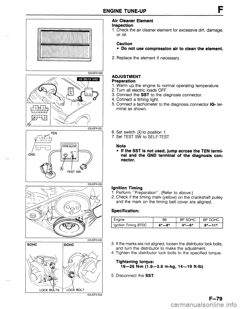
Air Cleaner Element
Inspection
1. Check the air cleaner element for excessive dirt, damage,
or oil.
Caution
l Do not use compression air to clean the element.
2. Replace the element if necessary.
ADJUSTMENT
Preparation
1. Warm up the engine to normal operating temperature.
2. Turn all electric loads OFF.
3. Connect the
SST to the diagnosis connector.
4. Connect a timing light.
5. Connect a tachometer to the diagnosis connector
IG- ter-
minal as shown.
6. Set switch @to position 1.
7. Set TEST SW to SELF-TEST.
Note
l If the SST is not used, jump across the TEN termi-
nal and the GND terminal of the diagnosis con-
nector.
Ignition Timing
1. Perform “Preparation”. (Refer to above.)
2. Check if the timing mark (yellow) on the crankshaft pulley
and the mark on the timing belt cover are aligned.
Specification:
Engine
Ignition Timing BTDC B6 BP SOHC BP DOHC
6O-8* 4O--6O go-110
SOHC DOHC
I 03UOFX-054
3. If the marks are not aligned, loosen the distributor lock bolts,
and turn the distributor to make the adjustment.
4. Tighten the distributor lock bolts to the specified torque.
Tightening torque:
19-25 N#m (1.9-2.6 m-kg, 14-19 ft-lb)
5. Disconnect the SST.
F-79