dimensions MAZDA PROTEGE 1992 Workshop Manual
[x] Cancel search | Manufacturer: MAZDA, Model Year: 1992, Model line: PROTEGE, Model: MAZDA PROTEGE 1992Pages: 1164, PDF Size: 81.9 MB
Page 520 of 1164

Jl TRANSAXLE
ASSEMBLY
Precaution
1. All O-rings and gaskets must be replaced with the new ones included in the overhaul kit.
2. Verify that all parts are completely clean before assembly.
3. Assemble parts within 10 minutes after applying sealant.
Allow all sealant to cure at least 30 minutes after assembly before filling the transaxle with transaxle oil.
4. The bearing outer race and bearing inner race must be replaced as a unit.
03UOJl-063
OBUOJl-06
-.--___
l-----o1
r-o-i
q----j H
I4
OBUOJI-065
03UOJl-06
SYNCHRONIZER RING
CLUTCH HUB SLEEVE
SYNCHRONIZER KEY 6
I
03UOJ l-067
51-30
Clutch hub assembly
Note
l Synchronizer ring diameters are as follows.
1st and 2nd
3rd and 4th
5th mm (in)
61.7 (2.429)
61.7 (2.429)
49.7 (1.957)
l Synchronizer key dimensions are as follows.
mm (in)
0 0
0
1 stl2nd 19.00 (0.748)
4.25 (0.167) 5.00 (0.197)
3rdl4th 17.00 (0.669)
4.25 (0.167) 5.00 (0.197)
5th
17.00 (0.669) 5.55 (0.219)
5.00 (0.197)
1. Install the synchronizer key springs in the clutch hub with
the hooks in the grooves to hold the three synchronizer keys
in place.
2. Align the synchronizer ring grooves with the synchronizer
key during assembly.
Page 575 of 1164

TRANSAXLE J2
1. Clutch hub
Assembly Note ,......................... page J2-27
2. Synchronizer key
3. Clutch hub sleeve
4. Synchronizer spring
5. Clutch hub
Assembly Note ,......................... page J2-27
6. Synchronizer key
7. Clutch hub sleeve (reverse gear)
8. Synchronizer spring
9. Primary shaft
10. Bearing inner race
Assembly Note . . . . . . . . . . . . . . . . . . . . . . . . . . page J2-28
11. 3rd gear
Assembly Note.. . . . . . . . . . . . . . . . . . . . page J2-28
12. Synchronizer ring (3rd)
Assembly Note.. . . . . . . . . . . . . . . . . . . page J2-28
13. Clutch hub assembly (3rd14th)
Assembly Note.. . . . . . . . . . . . . . . . . . . . page J2-28
14. Retaining ring
15. Synchronizer ring (4th)
Assembly Note . . . . . . . . . . . . . . . . . . . . . . . . . . page J2-28
16. 4th gear
Assembly Note . . . . . . . . . . . . . . . . . . . . . . . . . .
page J2-28
17. Bearing inner race
Assembly Note.. . . . . . . . . . . . . . . . . . page J2-28
18. Secondary shaft
19. Bearing inner race
Assembly Note . . . . . . . . . . . . . . . . . . . . . . . page J2-29 20. 1st gear
Assembly Note . . . . . . . . . . . . . . . . . . . . . . . . . . page J2-29
21. Synchronizer ring (1 st)
Assembly Note . . . . . . . . . . . . . . . . . . . . . . . . . .
page J2-29
22. Clutch hub assembly (IstMnd)
Assembly Note ,,..........,............. page J2-29
23. Retaining ring
24. Synchronizer ring (2nd)
Assembly Note . . . . . . . . . . . . . . . . . . . . . . . . . . page J2-29
25.2nd gear
Assembly Note . . . . . . . . . . . . . . . . . . . . . . . . . . page J2-29
26. Secondary 3rd gear
Assembly Note . . . . . . . . . . . . . . . . . . . . . . . . . .
page J2-29
27. Retaining ring
28. Secondary 4th gear
Assembly Note ,.,............,....,..... page J2-30
29. Bearing inner race
Assembly Note. . . . . . . . . . . . . . . . . . page J2-30
30. Control rod
31. Control lever
32. Roll pin
33. lst/2nd shift fork
34. Control end
35. Roll pin
36. Interlock sleeve
Assembly Note.. . . . . . . . . . . . . . . . page J2-30
37. 3rd/4th shift fork
03UOJ2 051
___-__ 03UOJ2-11
Assembly note
Clutch hub
Note
l Synchronizer key dimensions are as follows.
mm (in)
(l-1
12) 1\3>
_--
1stMnd 19 (0.7480) 4.25 (0.1673) -5.00 (0.1969)
3rdl4th
SthlRev. 17 (0.6693) 4.25 (0.1673) 5.00 (0.1969)
1. Install the synchronizer key springs in the clutch hub with
the hooks in the grooves to hold the three synchronizer keys
in place.
03UOJ2-052
J2-27
Page 669 of 1164

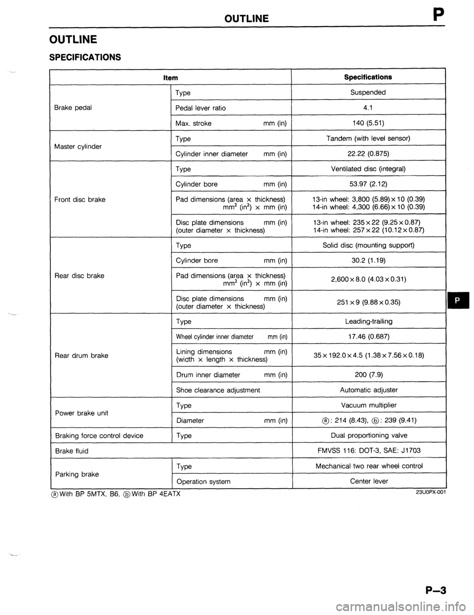
OUTLINE
OUTLINE
SPECIFICATIONS
item Specifications
Brake pedal
Master cylinder
Front disc brake
Rear disc brake
Rear drum brake
Power brake unit
Braking force control device
Brake fluid Type Suspended
Pedal lever ratio
I 4.1
I
Max. stroke mm (in) 140 (5.51)
I
Type
Cylinder inner diameter mm (in)
Type
Cylinder bore mm (in)
Pad dimensions (area x thickness)
mm’ (in2) x mm (in)
Disc plate dimensions mm (in)
(outer diameter x thickness) Tandem (with level sensor)
22.22 (0.875)
Ventilated disc (integral)
53.97 (2.12)
13-in wheel: 3,800 (5.89)x 10 (0.39)
14-in wheel: 4,300 (6.66) x 10 (0.39)
13-in wheel: 235 x 22 (9.25 x 0.87)
14-in wheel: 257 x 22 (10.12 x 0.87)
We
I Solid disc (mounting support)
I
Cylinder bore mm (in)
I 30.2 (1.19)
I
Pad dimensions (area x thickness)
mm2 (in’) x mm (in)
Disc plate dimensions mm (in)
(outer diameter x thickness)
Type 2,600 x 8.0 (4.03 x 0.31)
251 x 9 (9.88 x 0.35)
Leading-trailing
Wheel cylinder inner diameter mm (in) 17.46 (0.687)
I
Lining dimensions mm (in)
(width x length x thickness) 35x192.0x4.5 (1.38x7.56x0.18)
I
Drum inner diameter mm (in) 200 (7.9)
I
Shoe clearance adjustment Automatic adjuster
Vacuum multiplier
@ : 214 (8.43) @ : 239 (9.41)
Dual proportioning valve
FMVSS 116: DOT-3, SAE: J1703
Type
Diameter
Type mm (in)
Parking brake
Type
Operation system Mechanical two rear wheel control
Center lever I
3 With BP SMTX, B6, @With BP 4EATX
I I
23UOPX-001
P-3
Page 737 of 1164

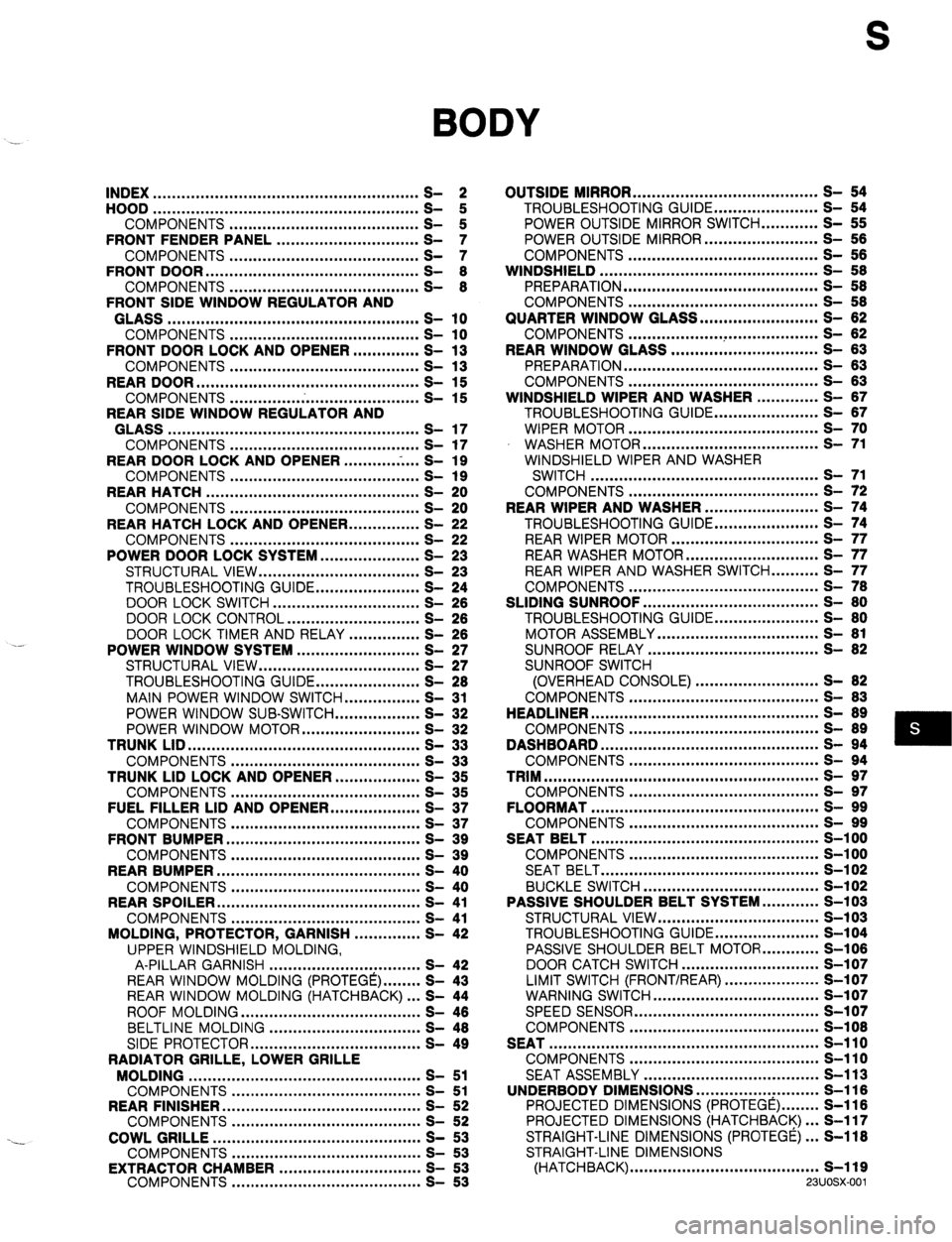
S
BODY
INDEX ........................................................ 2
HOOD ........................................................
COMPONENTS ........................................ t
FRONT FENDER PANEL .............................. ;I
COMPONENTS ........................................ S- ::
FRONT DOOR ............................................. S- 8
COMPONENTS ........................................ S- 8
FRONT SIDE WINDOW REGULATOR AND
GLASS ..................................................... s- 10
COMPONENTS ........................................ s- 10
FRONT DOOR LOCK AND OPENER .............. S- 13
COMPONENTS ........................................ s- 13
REAR DOOR ............................................... s- 15
COMPONENTS ........................................ s- 15
REAR SIDE WINDOW REGULATOR AND
GLASS ..................................................... s- 17
COMPONENTS ........................................ s- 17
REAR DOOR LOCK AND OPENER ...........
.-. ...
S- 19
COMPONENTS ........................................ s- 19
REAR HATCH ............................................. s- 20
COMPONENTS ........................................ s- 20
REAR HATCH LOCK AND OPENER.. .............
S- 22
COMPONENTS ........................................ s- 22
POWER DOOR LOCK SYSTEM.. ................... S- 23
STRUCTURAL VIEW .................................. S- 23
TROUBLESHOOTING GUIDE ...................... S- 24
DOOR LOCK SWITCH ............................... S- 28
DOOR LOCK CONTROL ............................ S- 26
DOOR LOCK TIMER AND RELAY ............... S- 26
POWER WINDOW SYSTEM .......................... S- 27
STRUCTURAL VIEW .................................. S- 27
TROUBLESHOOTING GUIDE.. .................... S- 28
MAIN POWER WINDOW SWITCH.. .............. S- 31
POWER WINDOW SUB-SWITCH.. ................ S- 32
POWER WINDOW MOTOR ......................... S- 32
TRUNK LID .................................................
s- 33
COMPONENTS ........................................ s- 33
TRUNK LID LOCK AND OPENER.. ................ S- 35
COMPONENTS ........................................ s- 35
FUEL FILLER LID AND OPENER ................... S- 37
COMPONENTS ........................................ s- 37
FRONT BUMPER ......................................... s- 39
COMPONENTS ........................................ s- 39
REAR BUMPER ........................................... s- 40
COMPONENTS ........................................ s- 40
REAR SPOILER ........................................... s- 41
COMPONENTS ........................................ s- 41
MOLDING, PROTECTOR, GARNISH .............. S- 42
UPPER WINDSHIELD MOLDING,
A-PILLAR GARNISH ................................ S- 42
REAR WINDOW MOLDING (PROTEGE) ........ S- 43
REAR WINDOW MOLDING (HATCHBACK) ... S- 44
ROOF MOLDING ...................................... S- 46
BELTLINE MOLDING ................................ S- 48
SIDE PROTECTOR.. .................................. S- 49
RADIATOR GRILLE, LOWER GRILLE
MOLDING ................................................. s- 51
COMPONENTS ........................................ S- 51
REAR FINISHER.. ........................................
S- 52
COMPONENTS ........................................ S- 52
COWL GRILLE ............................................ s- 53
COMPONENTS ........................................ s- 53
EXTRACTOR CHAMBER ..............................
COMPONENTS ........................................ g-
- ;; OUTSIDE MIRROR ....................................... s- 54
TROUBLESHOOTING GUIDE.. .................... S- 54
POWER OUTSIDE MIRROR SWITCH ............ S- 55
POWER OUTSIDE MIRROR.. ...................... S- 56
COMPONENTS ........................................ s- 66
WINDSHIELD .............................................. S- 58
PREPARATION ......................................... S- 58
COMPONENTS ........................................ S- 58
QUARTER WINDOW GLASS ......................... S- 62
COMPONENTS .................. ..T ................... S- 82
REAR WINDOW GLASS ............................... S- 63
PREPARATION ......................................... S- 63
COMPONENTS ........................................ S- 63
WINDSHIELD WIPER AND WASHER ............. S- 87
TROUBLESHOOTING GUIDE.. .................... S- 67
WIPER MOTOR ........................................ s- 70
WASHER MOTOR ..................................... s- 71
WINDSHIELD WIPER AND WASHER
SWITCH ................................................ s- 71
COMPONENTS ........................................ S- 72
REAR WIPER AND WASHER ........................ S- 74
TROUBLESHOOTING GUIDE.. .................... S- 74
REAR WIPER MOTOR ............................... s- 77
REAR WASHER MOTOR ............................ s- 77
REAR WIPER AND WASHER SWITCH.. ........ S- 77
COMPONENTS ........................................ S- 78
SLIDING SUNROOF ..................................... S- 80
TROUBLESHOOTING GUIDE.. .................... S- 80
MOTOR ASSEMBLY .................................. S- 81
SUNROOF RELAY .................................... S- 82
SUNROOF SWITCH
(OVERHEAD CONSOLE) .......................... S- 82
COMPONENTS ........................................ S- 83
HEADLINER ................................................ S- 89
COMPONENTS ........................................ S- 89
DASHBOARD .............................................. s- 94
COMPONENTS ........................................ s- 94
TRIM .......................................................... s- 97
COMPONENTS ........................................ s- 97
FLOORMAT ................................................ s- 99
COMPONENTS ........................................ s- 99
SEAT BELT ................................................ S-l 00
COMPONENTS ........................................ S-l 00
SEAT BELT .............................................. S-l 02
BUCKLE SWITCH ..................................... s-102
PASSIVE SHOULDER BELT SYSTEM.. .......... S-103
STRUCTURAL VIEW .................................. s-103
TROUBLESHOOTING GUIDE.. .................... S-104
PASSIVE SHOULDER BELT MOTOR.. .......... S-106
DOOR CATCH SWITCH ............................. S-l 07
LIMIT SWITCH (FRONT/REAR)
WARNING SWITCH ....................................................... z-:X;
-
SPEED SENSOR ....................................... s-i 07
COMPONENTS ........................................ S-l 08
SEAT ......................................................... s-110
COMPONENTS ........................................ s-110
SEAT ASSEMBLY ..................................... S-l 13
UNDERBODY DIMENSIONS .............. ..: ......... S-116
PROJECTED DIMENSIONS (PROTEGE) ........ S-116
PROJECTED DIMENSIONS (HATCHBACK). .. S-117
STRAIGHT-LINE DIMENSIONS (PROTEGE). .. S-118
STRAIGHT-LINE DIMENSIONS
(HATCHBACK) ........................................ s-119
23UOSX.001
Page 740 of 1164

S INDEX
1. Headliner
Components .............................
page S- 89 Components ............................. page S-l 10
2. Dashboard Seat assembly ..........................
page S-l 13
Components
............................. page S- 94 8. Underbody dimensions
3. Trim
Projected djmensions
Components
............................. page S- 97 (PROTEGE). ............................
page S-l 16
4. Floormat
Projected dimensions
Components ............................. page
S- 99 (Hatchback) ............................
page S-l 17
5. Seat belt
Straight-line, dimensions
Components ............................. page S-i 00 (PROTEGE). ............................ page
S-l 18
Seat belt ...................................
page S-102 Straight-line dimensions
Buckle switch.. .......................... page
S-102 (Hatchback) ............................
page S-l 19
6. Passive shoulder belt system
Structural view.. ........................
page S-103
Troubleshooting guide.. ............ page S-l 04
Passive shoulder belt motor..
... page S-l 06
Door catch switch..
................... page S-l 07
Limit switch.. ............................. page S-107
Warning switch
......................... page S-l 07
Speed sensor ........................... page
S-l 07
Components .............................
page S-l 08
s-4
Page 852 of 1164

S UNDERBODY DIMENSIONS
UNDERBODY DIMENSIONS
PROJECTED DIMENSIONS (PROTEGh
~rnoowu~
‘_,
S-116
Page 853 of 1164

UNDERBODY DIMENSIONS
PROJECTED DIMENSIONS (HATCHBACK)
. ----- -__
I
c
98(
L
"‘c,,:, -
I IN R T.
amvnwuc7
03UOSX-21
s-11;
Page 855 of 1164

UNDERBODY DIMENSIONS S
STRAIGHT-LINE DIMENSIONS (HATCHBACK)