glove box MAZDA PROTEGE 1992 Workshop Manual
[x] Cancel search | Manufacturer: MAZDA, Model Year: 1992, Model line: PROTEGE, Model: MAZDA PROTEGE 1992Pages: 1164, PDF Size: 81.9 MB
Page 831 of 1164

DASHBOARD S
1, Rear ashtray (Without passive IO. Combination switch 18. Glove box lid
shoulder belt) Removal / Installation 19. Lower panel (R.H.)
2. Rear console ,..,,.,......,,.,.,....... Section T 20. Front ashtray
3. Front console 11. Center upper hole cover 21. Lower panel (Center)
4. Control box center cover 12. Upper garnish
22. Glove box cover
(With small front console) 13. Side panel 23. Dash board
5. Side walls 14. Hood release knob Removal Note . . page S-95
6. Undercover 15. Lower panel (L.H.) Installation Note page S-96
7. Steering column 16. Meter hood 24. Pipe frame (Lower)
Removal / Installation 17. Instrument cluster 25. Pipe frame (Upper)
. . . . . . . . ...*. . . . . ..n..... Section N Removal I Installation
1 suosx-017
8. Key cylinder set ring
9. Column cover
JOINT BOX
. . . . . . . . . . . . . . . . . . . . . . . . . . Section T
Removal Note
Dashboard
1, Remove the control wires of the heater unit and blower unit.
2. Disconnect the necessary harness connectors.
s-95
Page 979 of 1164

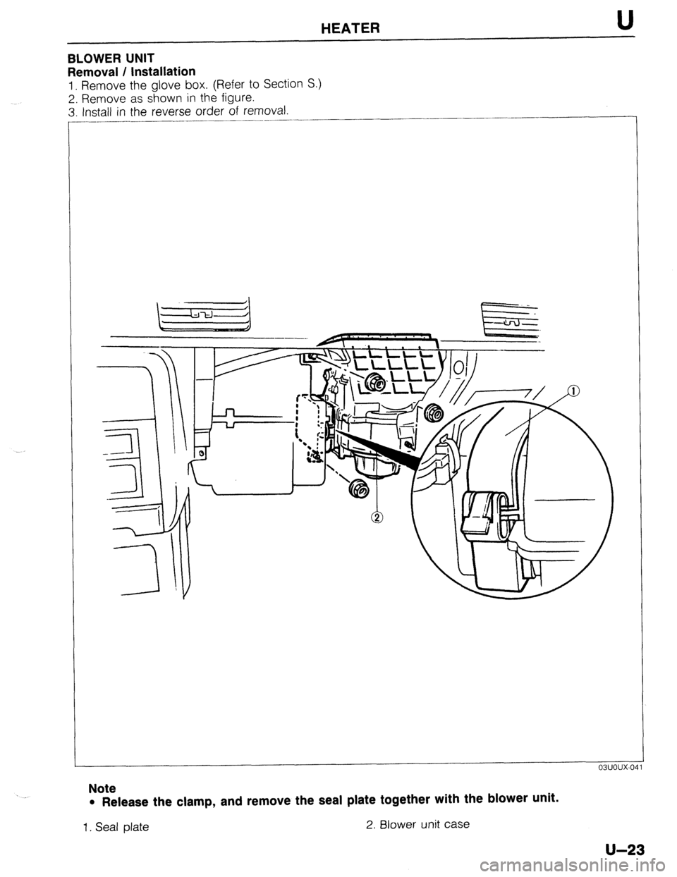
HEATER U
BLOWER UNIT
Removal / Installation
1. Remove the glove box. (Refer to Section S.)
2. Remove as shown in the figure.
3. Install in the reverse order of removal.
____..
Note
l Release the clamp, and remove the seal plate together with the blower unit.
1. Seal plate 2. Blower unit case
U-23
Page 981 of 1164

HEATER U
23UOUX-01
23uoux-02
Inspection
Blower motor
1, Remove the glove box. (Refer to Section S.)
2. Disconnect the blower motor connectors.
3. Verify that the blower motor runs when connecting battery
voltage to terminal a and grounding terminal b.
4. If not as specified, replace the blower motor.
Resistor assembly
1. Remove the glove box. (Refer to Section S.)
2. Disconnect the resistor assembly connectors.
3. Check continuity between terminals.
G-O: Indicates continuity
4. If not as specified, replace the resistor assembly.
u-25
Page 982 of 1164

U HEATER
HEATER CONTROL UNIT
Removal / Installation
1. Disconnect the negative battery cable.
2. Remove in the order shown in the figure.
3. Install in the reverse order of removal.
Note
l After installing the Mix, Mode, and Ret-Fresh wires. verifv that each lever moves its full stroke.
1. Side panel
2. Lower panel (R.H.)
3. Lower panel (Center)
4. Meter hood 5. Glove box
6. Glove box cover
7. Mode wire
8. Mix wire
9. Ret-Fresh wire
IO. Heater control assembly
U-26
Page 994 of 1164

U
COOLING UNIT
Removal / Installation AIR CONDITIONER
1. Discharge the refrigeration system. (Refer to page U-32.)
2. Remove the glove box, glove box cover, undercover, and instrument panel stay. (Refer to Section S.)
3. Remove the cooling unit as shown in the figure. -
Note
l Immediately plug all open fittings to keep moisture out of system.
4. Install the cooling unit in the reverse order of removal.
Note
l Position the cooling unit so that its connections match those of the heater unit and blower unit.
l Apply clean compressor oil to the O-rings before connecting the fittings.
l Do not apply compressor oil to the fitting nuts.
l When installing a new cooling unit, add compressor oil through the high-pressure pipe port
of the compressor.
Compressor oil: 50 cc (3.05 cu in)
Tightening torque
Outlet pipe: 20-29 N*m (2.0-3.0 m-kg, 14-22 ft-lb)
lnla+ nina. Q n,7n N.m (I -0-2.0 m&a. 7,7-IA ftJh IIllcvb yap”. “.” -1 . . . . . \..’ -_- __- ..~, JII .- .I .-,
23UOUX-0: -.,
1. Cooling unit
Disassembly / Assembly.. . . . . . . . . . . . page U-39
U-38
Page 996 of 1164

U AIR CONDITIONER
OFF
03UOUX-06
03UOUX-06,
03UOUX-06
On-vehicle Inspection
Thermoswitch
1. Remove the glove box.
2. Run the engine at idle.
3. Turn OFF the A/C switch and set the blower switch to the
highest position to operate the blower fan for a few minutes.
4. After a few minutes, turn OFF the blower switch and stop
the engine.
5. Disconnect the thermoswitch connector and check for con-
tinuity between terminals of the switch.
Terminals Continuity
a-b Yes
6. If not as specified, replace the thermoswitch.
Note
l The thermoswitch contacts will be open if the
evaporator temperature is below 0.4 f 0.7OC (32.7
z!z 1.3OF).
Inspection
Thermoswitch
1. Immerse the sensing bulb in a container of ice water.
2. Check continuity between terminals of the switch as
specified.
Terminals
a-b Temperature Continuity
Above 5°C Yes
Below 0% No
3. If not as specified, replace the thermoswitch
Evaporator
1. Check the evaporator fins for blockage. If the fins are
clogged, clean them with compressed air.
Caution
l Never use water to clean the evaporator.
2. Check the fittings for cracks and other damage.
Replace the evaporator if necessary.
u-40