height adjustment MAZDA PROTEGE 1992 Workshop Manual
[x] Cancel search | Manufacturer: MAZDA, Model Year: 1992, Model line: PROTEGE, Model: MAZDA PROTEGE 1992Pages: 1164, PDF Size: 81.9 MB
Page 5 of 1164
HOW TO USE THIS MANUAL GI
HOW TO USE THIS MANUAL
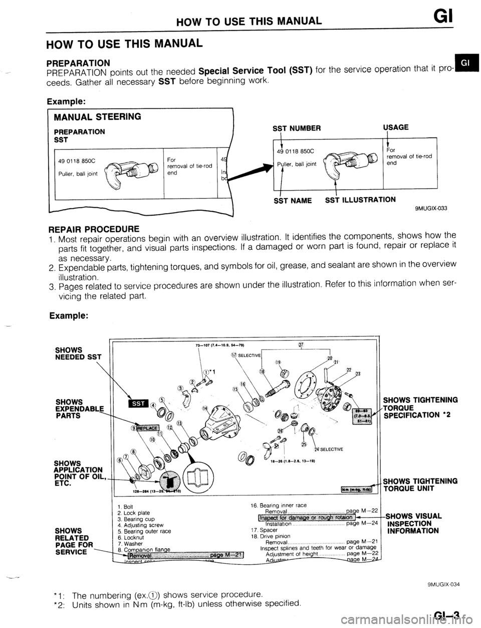
PREPARATION
PREPARATION points out the needed Special Service Tool (SST) for the service operation that it pro- m
ceeds. Gather all necessary
SST before beginning work.
Example:
49 0118 850C
removal of be-rod
9MUGIX-033
REPAIR PROCEDURE
1. Most repair operations begin with an overview illustration. It identifies the components, shows how the
parts fit together, and visual parts inspections. If a damaged or worn part is found, repair or replace it
as necessary.
2. Expendable parts, tightening torques, and symbols for oil, grease, and sealant are shown in the overview
illustration.
3. Pages related to service procedures are shown under the illustration. Refer to this information when ser-
vicing the related part.
Example:
SHOWS
NEEDED SST
SHOWS
APPLICATION
#T OF OIL,
SHOWS
RELATED
PAGE FOR
SERVICE ----
3. Bearing cup 1. Bolt
2. Lock Dlate
4. Adjusting screw
5. Bearing outer race
6. Locknut
7. Washer
8. Companion flange 16. Bearing Inner race
@ Removal. ,,,..,,,..
lnstallatlon page
page M--5 M-Z
i 7. Spacer
18. Drive pinion
Removal, .,,, ,.,, .,......... page M--i
Inspect spllnes and teeth for wear or damagl
Adjustment of height page M-2
Adurstp- w
SHOWS TIGHTENING
TORQUE
SPECIFICATION ‘2
SHOWS TIGHTENING
rORQlJE UNIT
SHOWS VISUAL
INSPECTION
INFORMATION
* 1: The numbering (ex.a) shows service procedure.
*2: Units shown in N.m (m-kg, ft-lb) unless otherwise specified.
9MUGIX-034
GI-3
Page 477 of 1164
CLUTCH PEDAL H
@ 14-19
(1.4-1.9, 10-13)
N.m (m-kg, R-lb)
CLUTCH PEDAL
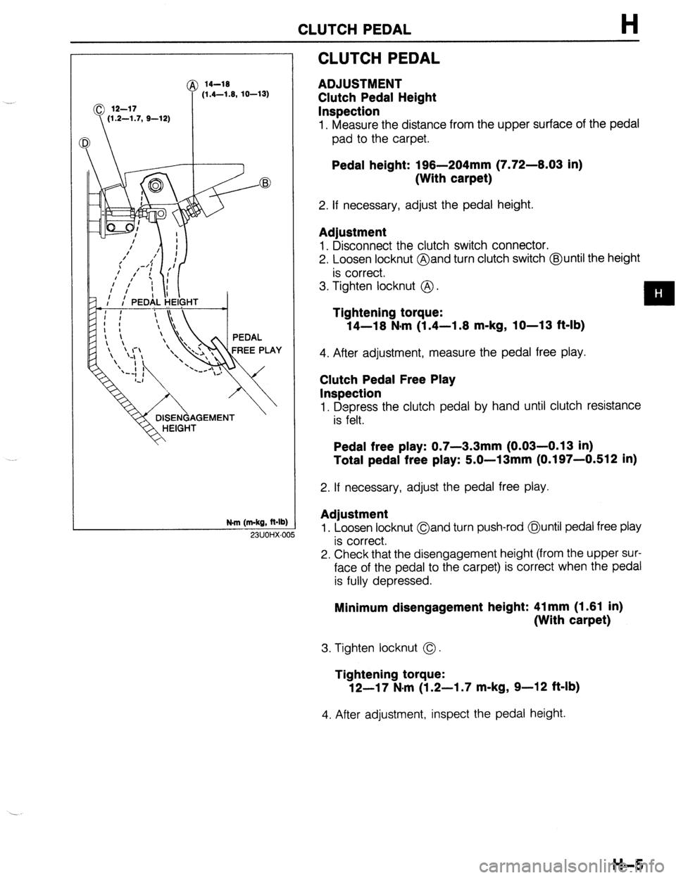
ADJUSTMENT
Clutch Pedal Height
Inspection
1. Measure the distance from the upper surface of the pedal
pad to the carpet.
Pedal height: 196-204mm (7.72-6.03 in)
(With carpet)
2. If necessary, adjust the pedal height.
Adjustment
1. Disconnect the clutch switch connector.
2. Loosen locknut @and turn clutch switch @until the height
is correct.
3. Tighten locknut @ .
Tightening torque:
14-16 N*m (1.4-1.6 m-kg, IO-13 f&lb)
4. After adjustment, measure the pedal free play.
Clutch Pedal Free Play
Inspection
1. Depress the clutch pedal by hand until clutch resistance
is felt.
Pedal free play: 0.7-3.3mm (0.03-0.13 in)
Total pedal free play: 5.0-13mm (0.197-0.512 in)
2. If necessary, adjust the pedal free play.
Adjustment
1. Loosen locknut Oand turn push-rod @until pedal free play
is correct.
2. Check that the disengagement height (from the upper sur-
face of the pedal to the carpet) is correct when the pedal
is fully depressed. 23UOHX-OC
Minimum disengagement height: 41 mm (1.61 in)
(With carpet)
3. Tighten locknut 0.
Tightening torque:
12-17 N-m (1.2-I .7 m-kg, 9-12 ft-lb)
4. After adjustment, inspect the pedal height.
H-5
Page 480 of 1164
H CLUTCH MASTER CYLINDER
23UOHX-Ot ,a
\ I 03UOHX-016
7
I
03UOHX-014
Removal Note
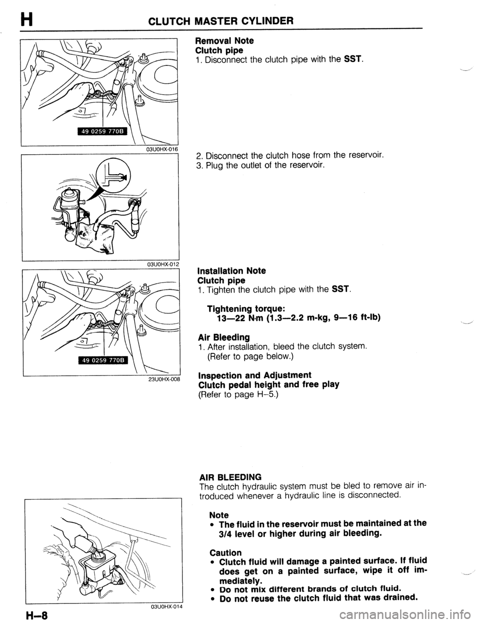
Clutch pipe
1, Disconnect the clutch pipe with the SST.
2. Disconnect the clutch hose from the reservoir.
3. Plug the outlet of the reservoir.
Installation Note
Clutch pipe
1. Tighten the clutch pipe with the SST.
Tightening torque:
13-22 N.m (1.3-2.2 m-kg, 9-16 ft-lb)
Air Bleeding
I. After installation, bleed the clutch system.
(Refer to page below.)
Inspection and Adjustment
Clutch pedal height and free play
(Refer to page H-5.)
AIR BLEEDING
The clutch hydraulic system must be bled to remove air in-
troduced whenever a hydraulic line is disconnected.
Note
l The fluid in the reservoir must be maintained at the
3/4 level or higher during air bleeding.
Caution
l Clutch fluid will damage a painted surface. If fluid
does get on a painted surface, wipe it off im-
mediately.
l Do not mix different brands of clutch fluid.
l Do not reuse the clutch fluid that was drained. __,
Page 674 of 1164

P CONVENTIONAL BRAKE SYSTEM
03UOPX.01
03UOPX-01
03UOPX-01
23UOPX-0
BRAKE FLUID
Inspection
Leakage inspection
Depress the brake pedal several times, and inspect for leak-
age of the brake line system. __,
Brake Fluid Level
Leakage check
Verify that the fluid level in the reservoir is between the MAX
and MIN lines on the reservoir.
Add fluid if it is below MAX.
Replacement
1. Follow the procedure outlined in Air Bleeding.
(Refer to page P-6).
2. Continue bleeding and replacing the brake fluid until only
clean fluid is expelled.
3. Fill the reservoir to the MAX level.
BRAKEPEDAL
Inspection, On-vehicle
Brake pedal height
Inspection
Verify that the distance from the center on the pedal pad to
the floor mat is as specified.
Specification: 193-196mm (7.60-7.72 in)
Adjustment
1. Disconnect the stoplight switch connector.
2. Loosen locknuts @J and turn switch @ until it does not con-
tact the pedal.
3. Loosen locknuts (I?J and turn rod @ to adjust the height
of the brake pedal.
4. Tighten the stoplight switch until it contacts the pedal; then
turn it an additional 112 turn. Tighten locknuts @ and @I.
5. Connect the stoplight switch connector.
6. Verify operation of the stoplights.
P-8
Page 675 of 1164

CONVENTIONAL BRAKE SYSTEM
03UOPX-021
PEDAL-TO-FLOOR
CLEARANCE
03UOPX-02
Pedal Play
Inspection
1. Depress the pedal a few times to eliminate the vacuum in
the system.
2. Gently depress the pedal by hand and check the free play
(until resistance is felt).
Pedal play: 4-7mm (0.16-0.26 in)
Adjustment
1. Loosen locknut @and turn rod @to adjust the free play.
2. Verify the pedal height and the stoplight operation.
Pedal-To-Floor Clearance
Inspection
Verifv that the distance from the floor panel to the center of
the pedal pad is as specified when the pedal is depressed
with a force of 569 N (60
kg, 132 lb).
Pedal-to-floor clearance: 70mm (2.76 in) min.
If the distance is less than specified, check for the following
problems:
1. Air in brake system
2. Malfunction of automatic adjuster (Rear drum brakes)
3. Worn shoes or pads
P-9
Page 713 of 1164
WHEEL ALIGNMENT
WHEEL ALIGNMENT
PRE-INSPECTION
1. Check the tire inflations and set to the recommended pressure, if necessary.
2. Inspect the front wheel bearing play; replace the bearing if necessary.
3. inspect the wheel and tire runout.
4. Inspect the ball joints and steering linkage for any excessive looseness.
5. The vehicle must be on level ground and have no luggage or passenger load.
6. The difference in height between the left and right sides from the center of the wheel to the fender brim
must not exceed
10mm (0.39 in).
7. Shake the vehicle to check operation of the shock absorbers.
03UORX.007
FRONT WHEEL ALIGNMENT
Specifications
item
Specifications
Maximum Inner 4o” f: 2O
steering angle Outer
33O f 2O
Total mm (in) 2 f 3 (0.08 f 0.12)
toe-in dearee 0.20 f 0.30 Wheel alignment
(*‘Unladen) Front
*I Fuel tank full; radiator coolant and Camber angle -0005 * 45’
Caster angle 1°55’ f 55’
Kingpin angle 12O25’
engine oil at specified level; and spare tire, jack, and tools in designated positions.
23UORX-008
I
I 23UORX-023
Adjustments
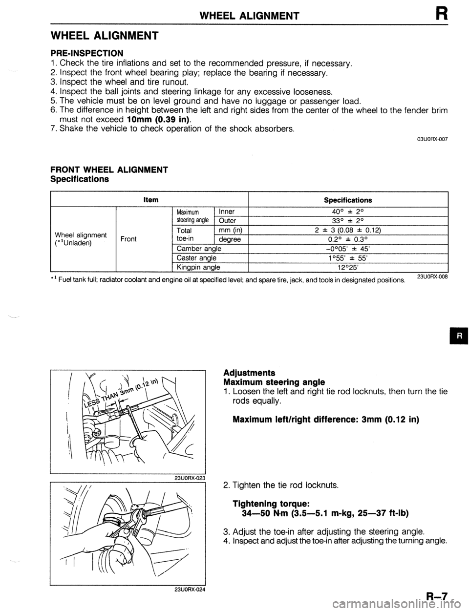
Maximum steering angle
1. Loosen the left and right tie rod locknuts, then turn the tie
rods equally.
Maximum left/right difference: 3mm (0.12 in)
2. Tighten the tie rod locknuts.
Tightening torque:
34-50 N-m (3.5-5.1 m-kg, 25-37 ft-lb)
3. Adjust the toe-in after adjusting the steering angle.
4. Inspect and adjust the toe-in after adjusting the turning angle.
I 23UORX-024
R-7
Page 770 of 1164
S TRUNK LID
03uosx-04’
HINGE (L.H.)
RIGHT SPRING -1
I
,i I
II
1
k
TRUNK LID
TRUNK LID
SEC.B--8
6 * 1.5 (0.31 * 0.06)
SECA-A mm (in)
03uosx-01
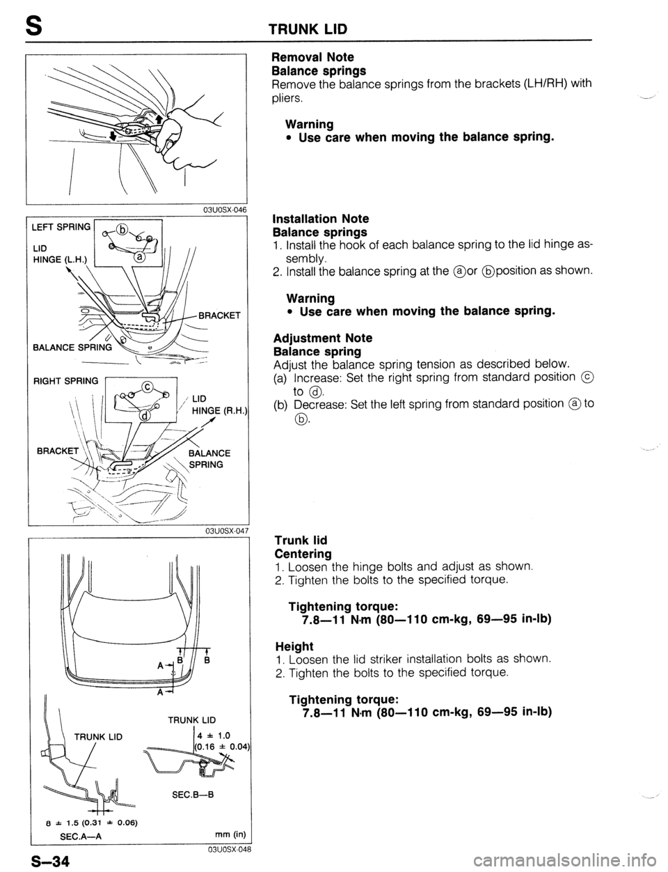
Removal Note
Balance springs
Remove the balance springs from the brackets (LH/RH) with
pliers.
Warning
l Use care when moving the balance spring.
Installation Note
Balance springs
1. Install the hook of each balance spring to the lid hinge as-
sembly.
2. Install the balance spring at the @or @position as shown.
Warning
l Use care when moving the balance spring.
Adjustment Note
Balance spring
Adjust the balance spring tension as described below.
(a) Increase: Set the right spring from standard position @
to @.
(b) Decrease: Set the left spring from standard position @to
03.
Trunk lid
Centering
1. Loosen the hinge bolts and adjust as shown.
2. Tighten the bolts to the specified torque.
Tightening torque:
7.8-l 1 N-m (80-l 10 cm-kg, 89-95 in-lb)
Height
1. Loosen the lid striker installation bolts as shown.
2. Tighten the bolts to the specified torque.
Tightening torque:
7.8-11 N-m (80-110 cm-kg, 89-95 in-lb)
s-34
Page 809 of 1164
WINDSHIELD WIPER AND WASHER S
ALIGNMEhT MARK
23UOSX.023
MOLDING END FACE
!6-
1.10-1.26)
/ COWL GRILLE END FACE
mm (in
o3uosx-l2!
tATCHBACK
-L I COWL dRlLLE
mm (in:
03uosx-131
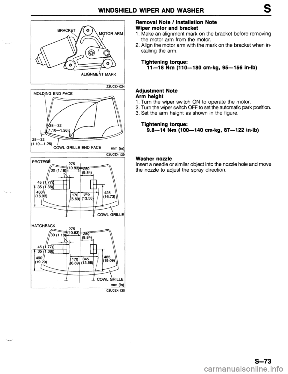
Removal Note / Installation Note
Wiper motor and bracket
1. Make an alignment mark on the bracket before removing
the motor arm from the motor.
2. Align the motor arm with the mark on the bracket when in-
stalling the arm.
Tightening torque:
1 l-18 N,m (1 lo-180 cm-kg, 95-158 in-lb)
Adjustment Note
Arm helght
1. Turn the wiper switch ON to operate the motor.
2. Turn the wiper switch OFF to set the automatic park position.
3. Set the arm height as shown in the figure.
Tightening torque:
9.8-14 N-m (100-140 cm-kg, 87-122 in-lb)
Washer nozzle
Insert a needle or similar object into the nozzle hole and move
the nozzle to adjust the spray direction.
s-73
Page 815 of 1164
REAR WIPER AND WASHER S
Wiper
Washer
1. Rear hatch lower trim
7. Trunk end trim
Removal / Installation . . . . . . . . . . . . . . . . page S-
98 Removal / Installation . . . . . . . . . . . . . . . . page
S- 98
2. Wiper arm cover 8. Trunk side cover
3. Rear wiper arm and blade Removal / Installation . . . . . . . . . . . . . . . . page S-
98
Adjustment
Note . . . . . . . . . . . . . . . . . . . . . . . page S- 79 9. Trunk side trim
4. Seal cap Removal / Installation . . . . . . . . . . . . . . . . page S-
98
5. Outer bushing 10. Rear header trim
6. Rear wiper motor Removal / Installation . . . . . . . . . . . . . . . . page S- 98
Inspection .,, ., . . . . . . . . . . . . . . . . . . . . . . . . . . . .
page S- 77 11. Rear seat belt upper anchor
Removal / Installation . . . . . . . . . . . . . . . . page S-l 01
12. C-pillar trim
Removal / Installation . . . . . . . . . . . . . . . . page S-
98
13. Washer tank assembly
a. Washer tank
b. Washer motor
Inspection . . . . . . . . . . . . . . . . . . . . . . . . . . . . . . . . .
page S- 77
14. Washer nozzle
Adjustment Note . . . . . . . . . . . . . . . . . . . . . . . page S-
79
15. Washer pipe
23UOSX-032
REAR WINDOW MOLDING
mm (in)
03uosx-14
REAR WINDQW MOLDING I
mm (in
03uosx-14
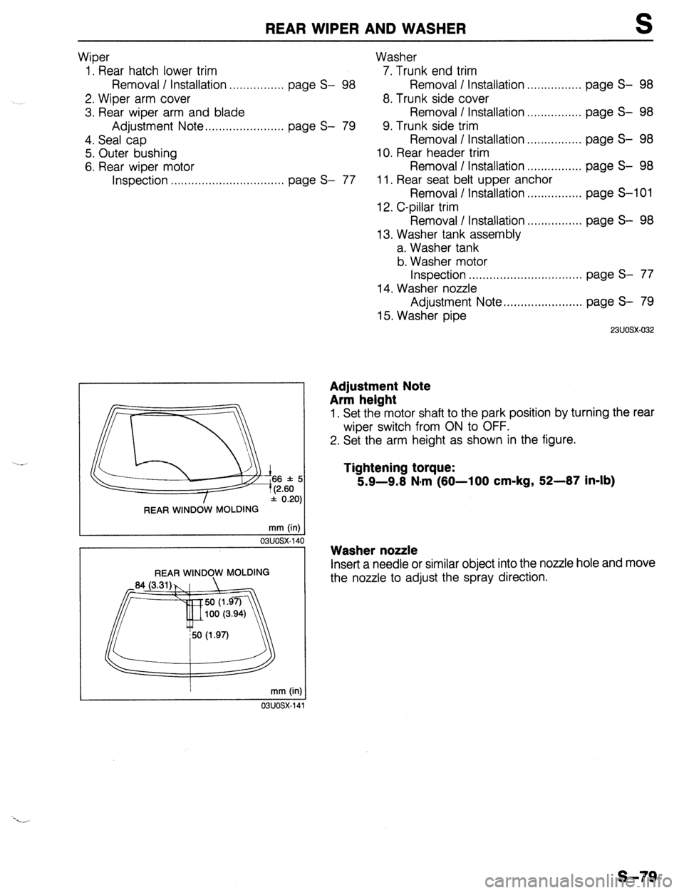
Adjustment Note
Arm height
1. Set the motor shaft to the park position by turning the rear
wiper switch from ON to OFF.
2. Set the arm height as shown in the figure.
Tightening torque:
5.9-9.8 N*m (80-100 cm-kg, 52-87 in-lb)
Washer nozzle
Inset-t a needle or similar object into the nozzle hole and move
the nozzle to adjust the spray direction.
s-79
Page 823 of 1164

SLIDING SUNROOF S
03UOSX-16d
(SUNROOF) (MOONROOF)
03UOSX-16!
ADJUSTING SCREW
SECA-A
D
__--__..-- ---__.-__
031JOSX 16
__-__
-~-
03UOSX-16
2. Install the guide rail cover and set plate.
3. Turn the motor using the emergency handle, and visually
check the sliding, tilt-down and tilt-up operations.
Adjustment Note
Sliding panel assembly
Height
Adjust so that the height difference between the sliding panel
and the roof panel is
1.5mm (0.06 in) max, referring to below.
(Front portion)
1. Loosen installation screws (1) and (2).
If the adjustment is only about
2mm (0.08 in) don’t loosen
screw (1).
2. Turn the screws to adjust.
Turning to the right raises; to the left lowers.
3. Tighten installation screws (1) and (2).
(Rear portion)
1. Loosen the adjusting screw.
2. Adjust by moving the sliding panel.
3. Tighten the adjusting screw.
S-987