instrument cluster MAZDA PROTEGE 1992 Workshop Manual
[x] Cancel search | Manufacturer: MAZDA, Model Year: 1992, Model line: PROTEGE, Model: MAZDA PROTEGE 1992Pages: 1164, PDF Size: 81.9 MB
Page 343 of 1164
![MAZDA PROTEGE 1992 Workshop Manual TROUBLESHOOTING GUIDE
27 MIL ALWAYS ON
DESCRIP- *Self-Diagnosis Checker does not indicate Malfunction Code No. but MIL always ON
TION
[TROUBLESHOOTING HINTS]
*Short circuit in wiring harness
l E MAZDA PROTEGE 1992 Workshop Manual TROUBLESHOOTING GUIDE
27 MIL ALWAYS ON
DESCRIP- *Self-Diagnosis Checker does not indicate Malfunction Code No. but MIL always ON
TION
[TROUBLESHOOTING HINTS]
*Short circuit in wiring harness
l E](/img/28/57077/w960_57077-342.png)
TROUBLESHOOTING GUIDE
27 MIL ALWAYS ON
DESCRIP- *Self-Diagnosis Checker does not indicate Malfunction Code No. but MIL always ON
TION
[TROUBLESHOOTING HINTS]
*Short circuit in wiring harness
l ECU malfunction
iTEF 1
1
-
s
Disconnect (Y/B) wire from ECU and check if
MIL goes off
‘YIB
ATX YIB
INSPECTION ACTION
Yes Replace ECU CT page F-149
No Check for short circuit in wiring be-
tween instrument cluster and ECU
23UOFX-042
28
MIL NEVER ON
IESCRIP- *Self-Diagnosis Checker indicates Malfunction Code No. of input device but MIL never ON
RON *Other indicator and warning lamps OK
:TROUBLESHOOTING HINTS]
b Bulb burned
‘Open circuit in wiring harness
m ECU malfunction
TEP INSPECTION
ACTION
1 Ground (Y/B) wire at ECU with jumper wire and
Yes Check connection of ECU connector
check if MIL comes on
MTX e If OK, replace ECU w page F-149
I- i -!~ !r--~r’:~;-‘;- --~_:- ,
1 i r 1 1 1 ;-.:,~;~$~& {-;&# ,$&]j 4 If not OK, repair ECU connector
! No
Check if bulb is OK
ATX 13 If OK, repair (Y/B) wire between
ECU and instrument cluster
e If not OK, replace bulb CT page T-83
23UOFX-043
29 A/C DOES NOT WORK
DESCRIP- *Blower fan operates but magnet clutch does not operate
TION
[TROUBLESHOOTING HINTS]
*Open or short circuit in wiring harness
*A/C relay, A/C switch, or magnetic clutch malfunction
l ECU malfunction
TEP/ INSPECTION ACTION
1 1 Check ECU
terminal 10 (MTX) 10 (ATX) voltage 1
Yes Check ECU terminal 1 J (MTX) 1 L (ATX)
OK
CT= page F-152
MTX
T7J++!;i”-
L
ATX
No voltage OK
CT page F-152
1-3 If OK, check A/C system
c3- page U-30
~3 If not OK, replace ECU CT page F-149
Check for cause w page F-153
F-77
Page 831 of 1164

DASHBOARD S
1, Rear ashtray (Without passive IO. Combination switch 18. Glove box lid
shoulder belt) Removal / Installation 19. Lower panel (R.H.)
2. Rear console ,..,,.,......,,.,.,....... Section T 20. Front ashtray
3. Front console 11. Center upper hole cover 21. Lower panel (Center)
4. Control box center cover 12. Upper garnish
22. Glove box cover
(With small front console) 13. Side panel 23. Dash board
5. Side walls 14. Hood release knob Removal Note . . page S-95
6. Undercover 15. Lower panel (L.H.) Installation Note page S-96
7. Steering column 16. Meter hood 24. Pipe frame (Lower)
Removal / Installation 17. Instrument cluster 25. Pipe frame (Upper)
. . . . . . . . ...*. . . . . ..n..... Section N Removal I Installation
1 suosx-017
8. Key cylinder set ring
9. Column cover
JOINT BOX
. . . . . . . . . . . . . . . . . . . . . . . . . . Section T
Removal Note
Dashboard
1, Remove the control wires of the heater unit and blower unit.
2. Disconnect the necessary harness connectors.
s-95
Page 843 of 1164

PASSIVE SHOULDER BELT SYSTEM S
DOOR CATCH SWITCH (in front door lock assembly)
Inspection
1. Disconnect the door catch switch connector.
2. Check for continuity between the terminals with an
ohmmeter.
031JOSX- 19
mm (in) Release
( +<>: lndtcates continuity
LIMIT SWITCH (FRONT/REAR)
Inspection
1. Disconnect the passive shoulder belt and front limit switch
connectors.
2. Position the shoulder belt buckle forward and rearward as
shown with the emergency handle.
3. Check for continuity between the limit switch terminals with
an ohmmeter.
Note
l Verify that the shoulder belt buckle is fully in the
front/rear lock position when checking.
Limit switch
Front
Rear
Buckle posItIon a b f h
Released (Front)
0 0
O---G Indicates continuity
4. If not as specified, replace the passive shoulder belt.
WARNING SWITCH (in passive shoulder belt retractor)
Inspection
1. Disconnect the warning switch connector.
2. Check for continuity between terminals when the lap belt
is pulled out/released.
Lap belt condition R.H. side
L.H. side
a b C d
I
Pulled (more than 80 cm (31.50 in) 1 0
Released
C&---i). Indicates continuity
SPEED SENSOR
Inspection
1. Remove the instrument cluster. (Refer to Section T.)
2. Check for continuity between terminals A and F while rotat-
ing the speedometer cable shaft.
3. If there are not four pulses per shaft rotation, replace the
speedometer. (Refer to Section T.)
S-l 07
Page 857 of 1164

BODY ELECTRICAL SYSTEM
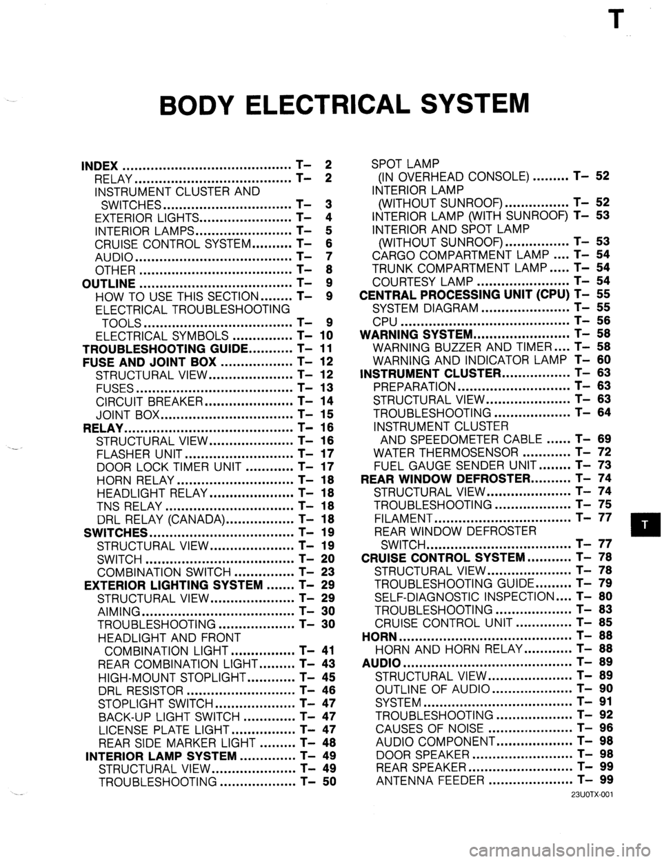
INDEX .......................................... T- 2
RELAY ....................................... T- 2
INSTRUMENT CLUSTER AND
SWITCHES ................................ T- 3
EXTERIOR LIGHTS.. ..................... T- 4
INTERIOR LAMPS.. ...................... T- 5
CRUISE CONTROL SYSTEM.. ........ T- 6
AUDIO ....................................... T- 7
OTHER ...................................... T- 8
OUTLINE ...................................... T- 9
HOW TO USE THIS SECTION.. ...... T- 9
ELECTRICAL TROUBLESHOOTING
TOOLS .....................................
ELECTRICAL SYMBOLS - ............... T- 1x
TROUBLESHOOTING GUIDE.. .........
T- 11
FUSE AND JOINT BOX ..................
T- 12
STRUCTURAL VIEW.. ...................
T- 12
FUSES ....................................... T- 13
CIRCUIT BREAKER.. ....................
T- 14
JOINT BOX ................................. T- 15
RELAY .......................................... T- 16
STRUCTURAL VIEW.. ...................
T- 16
.-
FLASHER UNIT ........................... T- 17
DOOR LOCK TIMER UNIT ............
T- 17
HORN RELAY ............................. T- 18
HEADLIGHT RELAY.. ................... T- 18
TNS RELAY ................................ T- 18
DRL RELAY (CANADA). ................ T- 18
SWITCHES .................................... T- 19
STRUCTURAL VIEW.. ................... T- 19
SWITCH ..................................... T- 20
COMBINATION SWITCH ...............
T- 23
EXTERIOR LIGHTING SYSTEM ....... T- 29
STRUCTURAL VIEW.. ...................
T- 29
AIMING ...................................... T- 30
TROUBLESHOOTING.. .................
T- 30
HEADLIGHT AND FRONT
COMBINATION LIGHT.. ..............
T- 41
REAR COMBINATION LIGHT.. ....... T- 43
HIGH-MOUNT STOPLIGHT.. .......... T- 45
DRL RESISTOR ........................... T- 46
STOPLIGHT SWITCH.. .................. T- 47
BACK-UP LIGHT SWITCH ............. T- 47
LICENSE PLATE LIGHT.. ..............
T- 47
REAR SIDE MARKER LIGHT ......... T- 48
INTERIOR LAMP SYSTEM ..............
T- 49
STRUCTURAL VIEW.. ...................
T- 49
TROUBLESHOOTING ...................
T- 50 SPOT LAMP
(IN OVERHEAD CONSOLE) ......... T- 52
INTERIOR LAMP
(WITHOUT SUNROOF). ............... T- 52
INTERIOR LAMP (WITH SUNROOF) T- 53
INTERIOR AND SPOT LAMP
(WITHOUT SUNROOF). ............... T- 53
CARGO COMPARTMENT LAMP.. .. T- 54
TRUNK COMPARTMENT LAMP.. ... T- 54
COURTESY LAMP ....................... T- 54
CENTRAL PROCESSING UNIT (CPU) T- 55
SYSTEM DIAGRAM ...................... T- 55
CPU .......................................... T- 56
WARNING SYSTEM.. ...................... T- 58
WARNING BUZZER AND TIMER .... T- 58
WARNING AND INDICATOR LAMP T- 60
INSTRUMENT CLUSTER.. ............... T- 63
PREPARATION ............................ T- 63
STRUCTURAL VIEW ..................... T- 63
TROUBLESHOOTING ................... T- 64
INSTRUMENT CLUSTER
AND SPEEDOMETER CABLE.. .... T- 89
WATER THERMOSENSOR ............ T- 72
FUEL GAUGE SENDER UNIT.. ...... T- 73
REAR WINDOW DEFROSTER.. ........ T- 74
STRUCTURAL VIEW.. ................... T- 74
TROUBLESHOOTING ................... T- 75
FILAMENT .................................. T- 77
REAR WINDOW DEFROSTER
SWITCH .................................... T- 77
CRUISE CONTROL SYSTEM.. ......... T- 78
STRUCTURAL VIEW.. ................... T- 78
TROUBLESHOOTING GUIDE.. ....... T- 79
SELF-DIAGNOSTIC INSPECTION .... T- 80
TROUBLESHOOTING ................... T- 83
CRUISE CONTROL UNIT .............. T- 85
HORN ........................................... T- 88
HORN AND HORN RELAY.. .......... T- 88
AUDIO .......................................... T- 89
STRUCTURAL VIEW.. ................... T- 89
OUTLINE OF AUDIO.. .................. T- 90
SYSTEM ..................................... T- 91
TROUBLESHOOTING ................... T- 92
CAUSES OF NOISE ..................... T- 96
AUDIO COMPONENT.. ................. T- 98
DOOR SPEAKER .........................
REARSPEAKER .......................... ;-
- !3;
ANTENNA FEEDER ..................... T- 99
23UOTX-001
Page 859 of 1164

INDEX T
INSTRUMENT CLUSTER AND SWITCHES
23UOTX-00
1. Rear window defroster switch
7. Fuel gauge sender unit
Inspection
........................... page T-21 Removal / Installation ..................
page T-73
2. Remote control door mirror switch
Inspection ................................... page T-73
Inspection
........................... page T-20 8. Hazard warning switch
3. Ignition switch
Removal / installation .................. page T-20
Removal / Installation..
........ page T-20 Inspection ................................... page T-21
Inspection ........................... page
T-2 1 9. Cruise control main switch
4. Combination switch Inspection ...................................
page T-21
Removal / installation
.......... pages T-23, 25 10. Cruise control switch
Disassembly / Assembly ..... pages T-24, 26 Removal / Installation ..................
page T-20
Inspection
........................... pages T-27, 28 Inspection ................................... page T-21
5. Instrument cluster 11. Power window main switch
Troubleshooting..
................ page T-65 Inspection ................................... page T-22
Removal / Installation
.......... page T-69 12. Power window switch
Disassembly I Assembly ..... page T-70 Inspection ................................... page T-22
Inspection
........................... page T-71 13. Panel lamp control switch
6. Water thermosensor
Inspection ................................... page T-22
Removal / Installation..
........ page T-72
Inspection ........................... page T-72
T-3
Page 867 of 1164

TROUBLESHOOTING GUIDE T
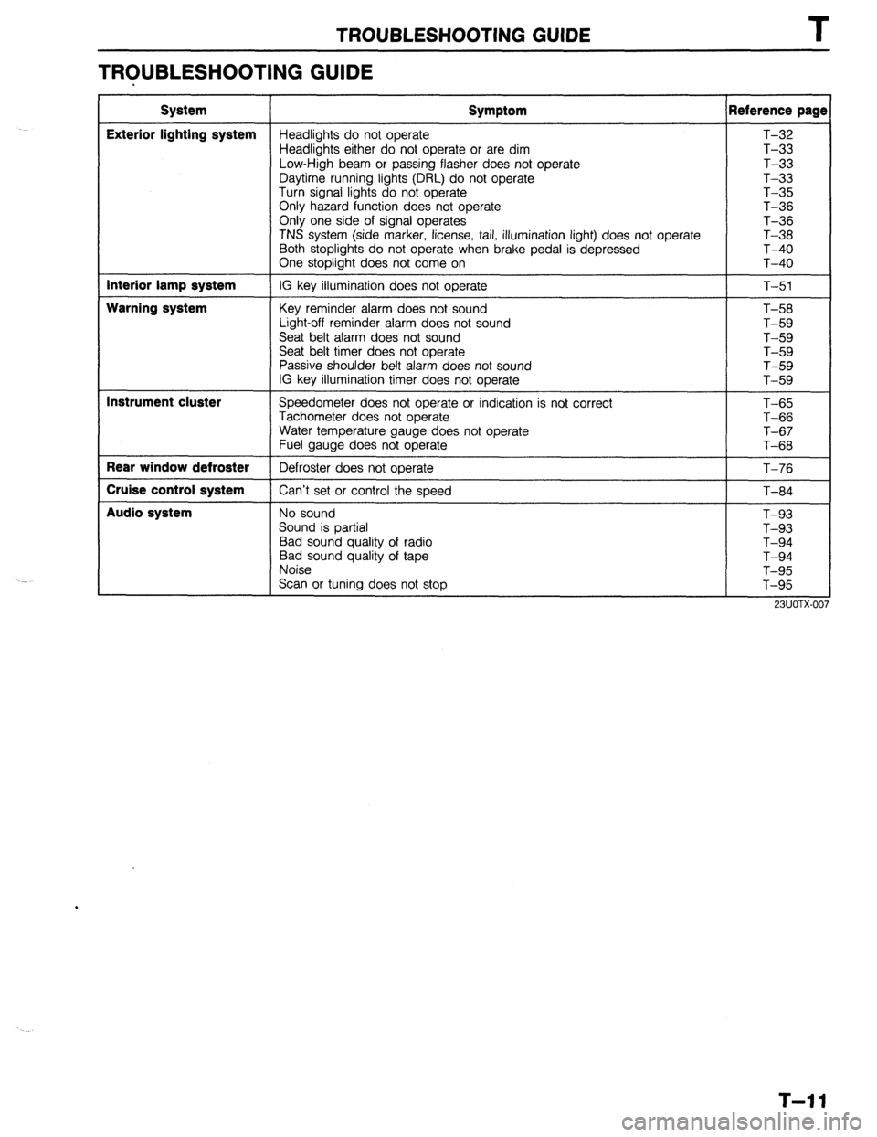
TROUBLESHOOTING GUIDE
System
Exterior lighting system
Interior lamp system
Warning system
Instrument cluster
Rear window defroster
Cruise control system
Audio system Symptom Reference page
Headlights do not operate T-32
Headlights either do not operate or are dim T-33
Low-High beam or passing flasher does not operate T-33
Daytime running lights (DRL) do not operate T-33
Turn signal lights do not operate T-35
Only hazard function does not operate T-36
Only one side of signal operates
T-36
TNS system (side marker, license, tail, illumination light) does not operate T-38
Both stoplights do not operate when brake pedal is depressed T-40
One stoplight does not come on T-40
IG key illumination does not operate
T-51
Key reminder alarm does not sound
Light-off reminder alarm does not sound
Seat belt alarm does not sound
Seat belt timer does not operate
Passive shoulder belt alarm does not sound
IG key illumination timer does not operate T-58
T-59
T-59
T-59
T-59
T-59
Speedometer does not operate or indication is not correct
Tachometer does not operate
Water temperature gauge does not operate
Fuel gauge does not operate
Defroster does not operate
Can’t set or control the speed T-65
T-66
T-67
T-68
T-76
T-84
No sound
Sound is partial
Bad sound quality of radio
Bad sound quality of tape
Noise
Scan or tuning does not stop T-93
T-93
T-94
T-94
T-95
T-95
T-l 1
Page 887 of 1164

CANADA lDAYTIME RUNNING LIGHTS
E-2
BATTFRY
UN CONTROL UNIT
G (Fl G/Y IF) G/R IF1
INSTRUMENT INSTRUMENT
CLUSTER Cl USTER
(SECTION C) (SECTION C)
WITH
CRUISE CONTROL ‘HEADL1GHTS E-2
MAIN
BOA
COMBINATION EXCEPT
SWITCH ~~;~~~;ENT/cnNnon
(SECTION cl
(!I
cI 4*0*
r----- ORL CONTROL 7
(SECTION E-31
-02 COMBINATION E-03 HEADLIGHT LH(F) E-04 HEADLIGHT FIti
SWITCH (Fl E-05 HEADLIGHT “Et$
-06 TAILLIGHT “E:;;
Page 918 of 1164

T
I WARNING SYSTEM
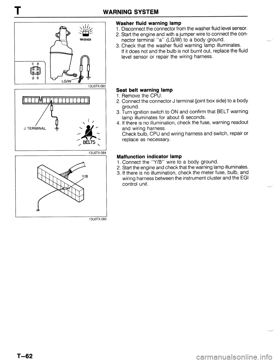
Washer fluid warning lamp
1. Disconnect the connector from the washer fluid level sensor.
2. Start the engine and with a jumper wire to connect the con-
nector terminal “a” (LGIW) to a body ground.
3. Check that the washer fluid warning lamp illuminates.
If it does not and the bulb is not burnt out, replace the fluid
level sensor or repair the wiring harness.
13UOTX-08
_-
1 /
J TERMINAL -
13UOTX-08
13UOTX-08
Seat belt warning lamp
1, Remove the CPU.
2. Connect the connector J terminal (joint box side) to a body
ground.
3. Turn ignition switch to ON and confirm that BELT warning
lamp illuminates for about 6 seconds.
4. If there is no illumination, check the fuse, warning readout
and wiring harness.
Check bulb, CPU and wiring harness and switch, repair or
replace as necessary.
Malfunction indicator lamp
1, Connect the “Y/B” wire to a body ground.
2. Start the engine and check that the warning lamp illuminates.
3. If there is no illumination, check the meter fuse, bulb, and
wiring harness between the instrument cluster and the EGI
control unit.
T-62
Page 919 of 1164

INSTRUMENT CLUSTER T
INSTRUMENT CLUSTER
PREPARATION
SST
I
I
49 0839 285
Checker, fuel
thermometer For
inspection of fuel
and water
temperature
gauge
I I
I
23UOTX-038
STRUCTURAL VIEW
WITH TACHOMETER (2WD)
WITHOUT TACHOMETER (2WD)
1. Speedometer 4. Fuel gauge
Troubleshooting . . . . . . . ..*................ page T-64 Troubleshooting . . . . . . . . . . . . . . . . . . . . . . . . . . page T-64
Inspection .,.......,,.......,,...,,.......... page T-71 Inspection . . . . . . . . . . . . . . . . . . . . . . . . . . . . . . . . . . . page T-71
2. Tachometer 5. Warning and indicator
Troubleshooting ..,....................... page T-64 Inspection ,.......,,......................... page T-61
inspection . . . . . . . . . . . . . . . . . . . . . . . . . . . . . . . . . . page T-71 6. Odometer
3. Water temperature gauge 7. Tripmeter
Troubleshooting . . . . . . . . . . . . . . . . . . . . . . . . . . page T-64
Inspection .,,........,,,,......,,............ page T-72
T-63
Page 921 of 1164

INSTRUMENT CLUSTER
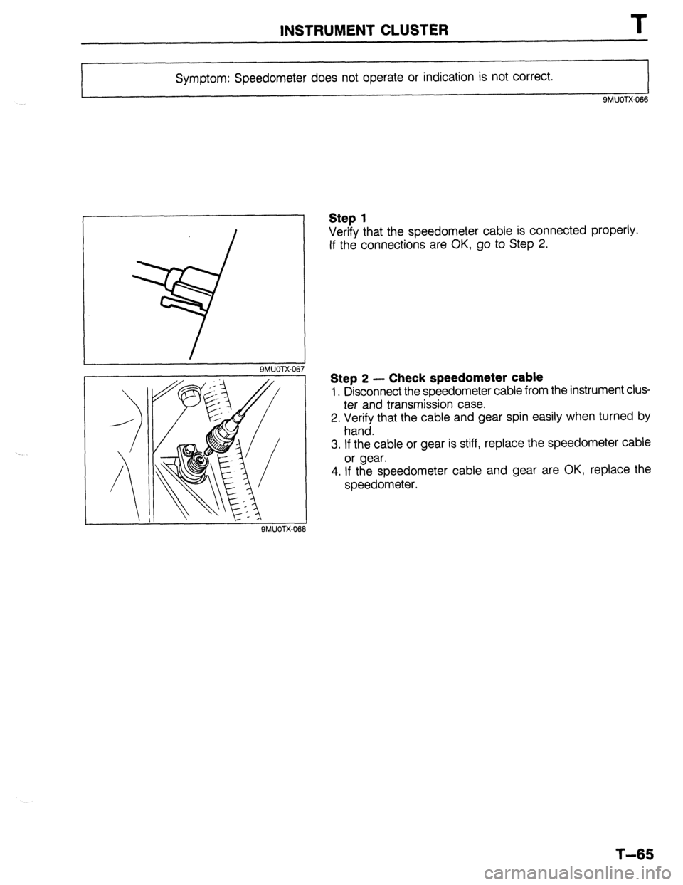
Symptom: Speedometer does not operate or indication is not correct.
9MUOTX-066
I 9MUOTX-067
Step 1
Verify that the speedometer cable is connected properly.
If the connections are OK, go to Step 2.
Step 2 - Check speedometer cable
1. Disconnect the speedometer cable from the instrument clus-
ter and transmission case.
2. Verify that the cable and gear spin easily when turned by
hand.
3. If the cable or gear is stiff, replace the speedometer cable
or gear.
4. If the speedometer cable and gear are OK, replace the
speedometer.
QMUOTX-068
T-65