instrument cluster MAZDA PROTEGE 1992 User Guide
[x] Cancel search | Manufacturer: MAZDA, Model Year: 1992, Model line: PROTEGE, Model: MAZDA PROTEGE 1992Pages: 1164, PDF Size: 81.9 MB
Page 922 of 1164
T INSTRUMENT CLUSTER
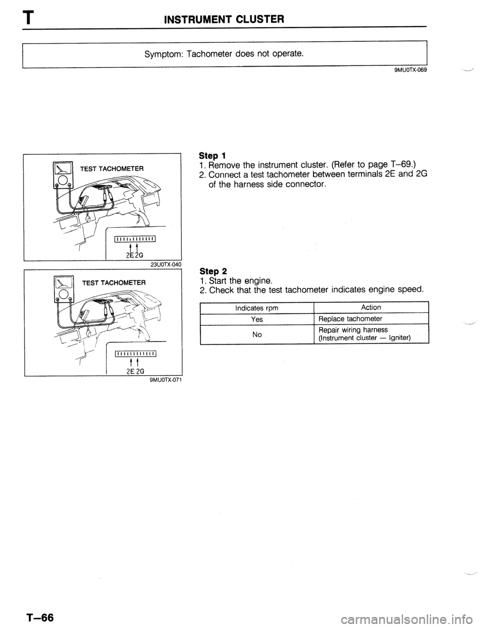
Symptom: Tachometer does not operate.
9MUOTX.069
TEST TACHOMETER
23UOTX-040
2E 2G SMUOTX-01
Step 1
1. Remove the instrument cluster. (Refer to page T-69.)
2. Connect a test tachometer between terminals 2E and 2G
of the harness side connector.
Step 2
1. Start the engine.
2. Check that the test tachometer indicates engine speed.
Indicates rpm
Yes
No Action
Replace tachometer
Repair wiring harness
(Instrument cluster - Igniter)
T-66
Page 923 of 1164
INSTRUMENT CLUSTER T
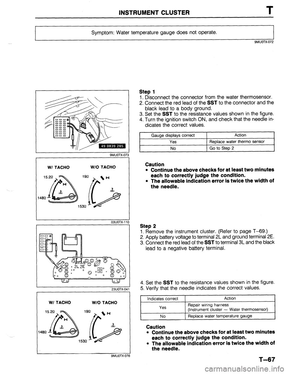
Symptom: Water temperature gauge does not operate.
9MUOTX-072
W/ TACHO W/O TACHO
OSUOTX-111
0
23UOTX-041
WI TACHO
W/O TACHO
9MUOTX-076
Step 1
1. Disconnect the connector from the water thermosensor.
2. Connect the red lead of the
SST to the connector and the
black lead to a body ground.
3. Set the
SST to the resistance values shown in the figure.
4. Turn the ignition switch ON, and check that the needle in-
dicates the correct values.
Gauge displays correct Action
Yes Replace water therm0 sensor
No Go to Step 2
Caution
l Continue the above checks for at least two minutes
each to correctly judge the condition.
l The allowable indication error is twice the width of
the needle.
Step 2
1. Remove the instrument cluster. (Refer to page T-69.)
2. Apply battery voltage to terminal 2L and ground terminal 2E.
3. Connect the red lead of the
SST to terminal 3L and the black
lead to a negative battery terminal.
4. Set the
SST to the resistance values shown in the figure.
5. Verify that the needle indicates the correct values.
Indicates correct
Yes Action
Repair wiring harness
(instrument cluster - Water thermosensor)
I--~ No I ReDlace water temperature gauge
I
Caution
l Continue the above checks for at least two minutes
each to correctly judge the condition.
l The allowable indication error is twice the width of
the needle.
T-67
Page 924 of 1164

T INSTRUMENT CLUSTER
Symptom: Fuel gauge does not operate.
SMUOTX-077 -_d
,
1
OBUOTX-186
W/ TACHO W/O TACHO
7R 7cl
9MUOTX-079
23UOTX-04:
WI TACHO W/O TACHO
7Q 7cl
Step 1
1. Disconnect the connector from the fuel gauge sender unit.
2. Connect the red lead of the SST to the terminal-wire (Y) and
the black lead to a body ground.
3. Set the SST to the resistance values shown in the figure.
4. Turn the ignition switch ON, and verify that the needle indi-
cates the correct values.
Indicates correct Action
Yes Replace fuel gauge sender unit (in fuel tank)
/
No Go
to Step 2
Caution
l Continue the above checks for at least two minutes
each to correctly judge the condition.
l The allowable indication error is twice the width of
the needle.
Step 2
1. Remove the instrument cluster. (Refer to page T-69.)
2. Apply battery voltage to terminal 2L and ground terminal 2E.
3. Connect the red lead of the SST to terminal 1C and the
black lead to a negative battery terminal.
4. Set the SST to the resistance values shown in the figure.
5. Verify that the needle indicates the correct values.
Indicates correct Action
Yes Repair wiring harness
(Instrument cluster - fuel gauge sender unit)
No Replace fuel gauge sender unit
Caution
. Continue the above checks for at least two minutes
each to correctly judge the condition.
l The allowable indication error is twice the width of
the needle. .-/
Page 925 of 1164
INSTRUMENT CLUSTER
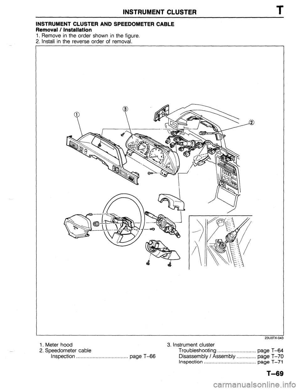
INSTRUMENT CLUSTER AND SPEEDOMETER CABLE
Removal / Installation
1. Remove in the order shown in the figure.
2. Install in the reverse order of removal.
1. Meter hood
3. Instrument cluster
23UOTX-04
...
2. Speedometer cable Troubleshooting
.......................... page T-64
Inspection ................................... page T-66
Disassembly / Assembly .............
page T-70
Inspection ...................................
page T-71
T-69
Page 926 of 1164
T INSTRUMENT CLUSTER
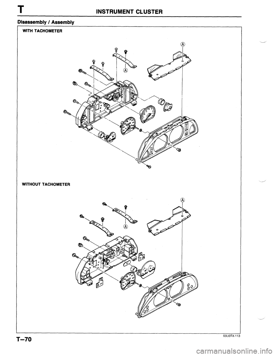
WITH TACHOMETER
WITHOUT TACHOMETER
Disassembly / Assembly
03UOTX.11
T-70
Page 927 of 1164
INSTRUMENT CLUSTER T
(For Canada)
(For USA)
11
OSUOTX-114
Standard Indication
(rpm)
1,000
2,000
3,000
4,000
5,000
6,000
7,000
8,000 Allowable range
@pm)
880-l ,060
1,970-2,150
3,000-3,180
4,000-4,240
5,000-5,300
6,000-6,360
7.000-7.420
8:600-8:480
03UOTX-11 5
I 23UOTX-044 WI TACHO WIO MACHO
32.50
ssn
9MUOTX-087
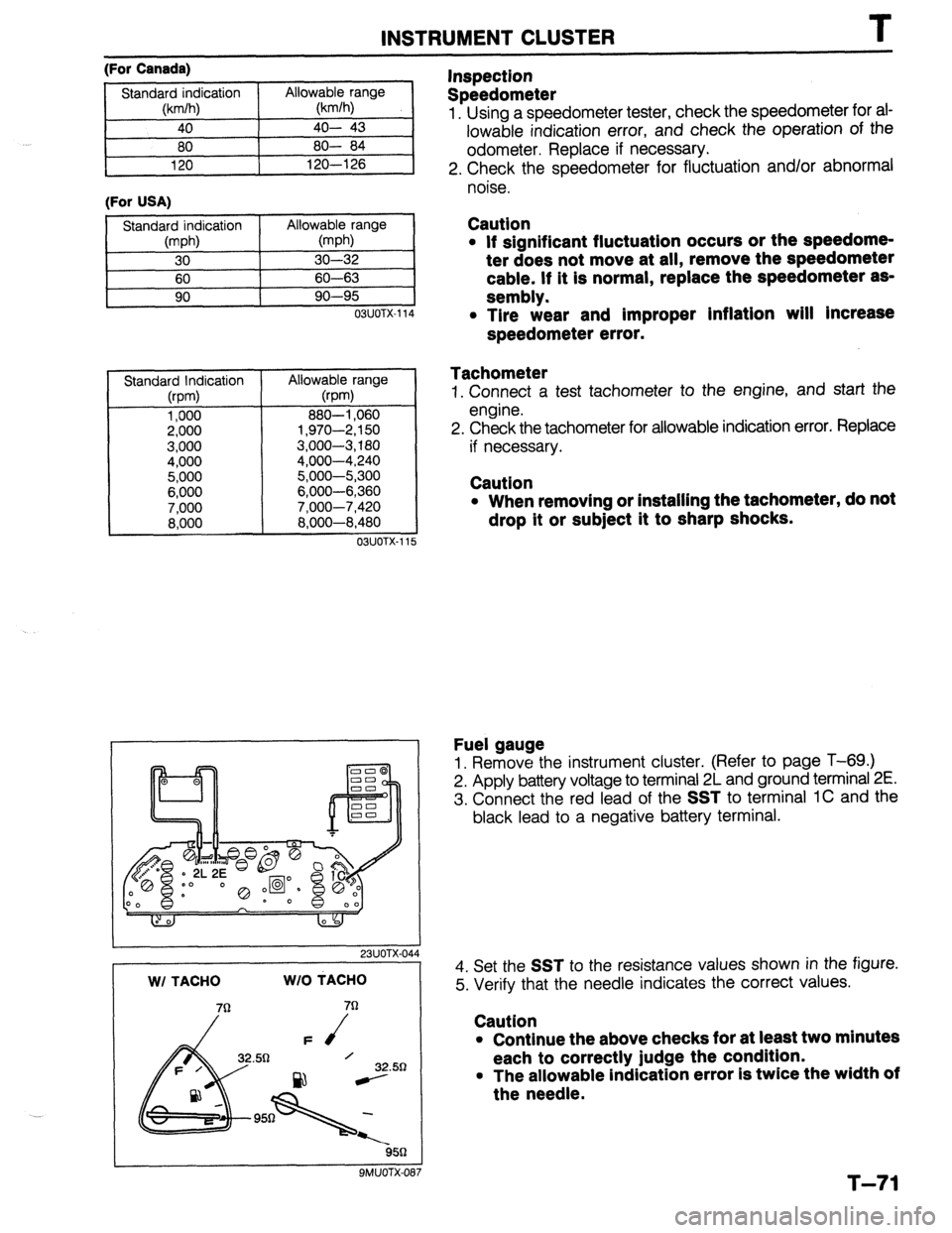
Inspection
Speedometer
1. Using a speedometer tester, check the speedometer for ai-
lowable indication error, and check the operation of the
odometer. Replace if necessary.
2. Check the speedometer for fluctuation and/or abnormal
noise.
Caution
l If significant fluctuation occurs or the speedome-
ter does not move at all, remove the speedometer
cable. If it is normal, replace the speedometer as-
sembly.
l Tire wear and improper inflation will Increase
speedometer error.
Tachometer
1. Connect a test tachometer to the engine, and start the
engine.
2. Check the tachometer for allowable indication error. Replace
if necessary.
Caution
l When removing or installing the tachometer, do not
drop it or subject it to sharp shocks.
Fuel gauge
1. Remove the instrument cluster. (Refer to page T-69.)
2. Apply battery voltage to terminal 2L and ground terminal 2E.
3. Connect the red lead of the
SST to terminal 1C and the
black lead to a negative battery terminal.
4. Set the
SST to the resistance values shown in the figure.
5. Verify that the needle indicates the correct values.
Caution
l Continue the above checks for at least two minutes
each to correctly judge the condition.
l The allowable indication error is twice the width of
the needle.
T-71
Page 928 of 1164
T INSTRUMENT CLUSTER
I
23UOTX-045
W/ TACHO WI0 TACHO
QMUOTX-08!
03UOTX- 11,
03UOTX.11
OBUOTX-
T-72
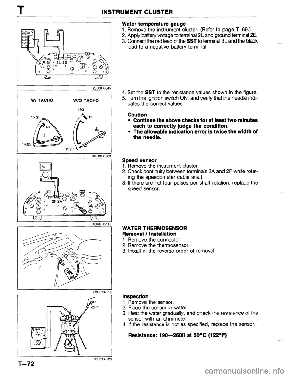
Water temperature gauge
1. Remove the instrument cluster. (Refer to page T-69.)
2. Apply battery voltage to terminal 2L and ground terminal 2E.
3. Connect the red lead of the SST to terminal 3L and the black
lead to a negative battery terminal.
____,
4. Set the SST to the resistance values shown in the figure.
5. Turn the ignition switch ON, and verify that the needle indi-
cates the correct values.
Cautlon
l Continue the above checks for at least two minutes
each to correctly judge the condition.
l The allowable indication error is twice the width of
the needle.
Speed sensor
1. Remove the instrument cluster.
2. Check continuity between terminals 2A and 2F while rotat-
ing the speedometer cable shaft.
3. If there are not four pulses per shaft rotation, replace the
speed sensor.
WATER THERMOSENSOR
Removal / Installation
1. Remove the connector.
2. Remove the thermosensor.
3. Install in the reverse order of removal.
Inspection 1.
Remove the sensor.
2. Place the sensor in water.
3. Heat the water gradually, and check the resistance of the
sensor with an ohmmeter. 4.
If the resistance is not as specified, replace the sensor.
Resistance: 190-2603 at 5O*C (122OF)
Page 929 of 1164
INSTRUMENT CLUSTER T
03UOTX-12
32.51
2
03UOTX-122
PROTEGli
32.58
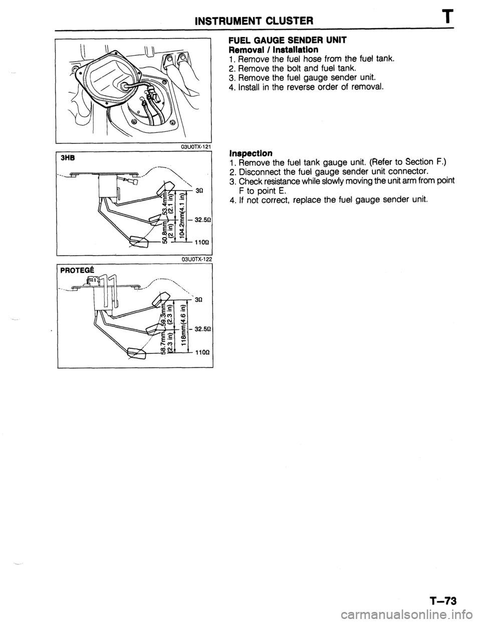
FUEL GAUGE SENDER UNIT
Removal / Installation
1. Remove the fuel hose from the fuel tank.
2. Remove the bolt and fuel tank.
3. Remove the fuel gauge sender unit.
4. Install in the reverse order of removal.
Inspection
1. Remove the fuel tank gauge unit. (Refer to Section F.)
2. Disconnect the fuel gauge sender unit connector.
3. Check resistance while slowly moving the unit arm from point
F to point E.
4. If not correct, replace the fuel gauge sender unit.
T-73
Page 1050 of 1164

PARTS INDEX
I
CRANKSHAFT.. ....................................
I31 -64
CYLINDER BLOCK .............................. 61-60
CYLINDER HEAD..
............................... 81-54
CYLINDER HEAD GASKET .................
Bl-16
DRIVE BELT(S). ...................................... 81-5
FRONT OIL SEAL ................................ 81-23
HLA .............................................. Bl-7,20,60
OIL JET ................................................ 81-61
PISTON.. ...............................................
Bl-62
PISTON PIN..
........................................ 81-62
PISTON RING
....................................... 81-62
REAR
OIL SEAL..
................................. 81-25
TENSIONER, IDLER ............................. Bl-65
TENSIONER
SPRING ...........................
Bl-65
TIMING BELT ..................................
Bl-12,65
TIMING BELT PULLEY ........................
Bl-65
VALVE MECHANISM ........................... Bl-55
ENGINE
(BP DOHC) .................................... B2-2
CAMSHAFT ..........................................
82-58
CAMSHAFT PULLEY ...........................
B2-65
CONNECTING ROD..
........................... 82-63
CRANKSHAFT ......................................
B2-64
CYLINDER BLOCK ..............................
82-60
CYLINDER
HEAD.. ............................... B2-54
CYLINDER HEAD GASKET .................
82-16
DRIVE
BELTS.. .......................................
B2-5
FRONT
OIL SEAL ................................
82-26
H LA ..............................................
OIL JET .......................... B2-7iyL;;
......................
PISTON .................................................
B2-62
PISTON PIN ..........................................
82-62
PISTON RING..
..................................... 82-62
REAR OIL SEAL ................................... B2-28
TENSIONER, IDLER ............................. B2-65
TENSIONER SPRING ........................... B2-65
TIMING
BELT.. ................................
B2-12,65
TIMING BELT PULLEY ........................ 82-65
VALVE MECHANISM ........................... 82-55
ENGINE CONTROL UNIT (ECU) ............... F-149
ENGINE COOLANT
........................................ E-5
ENGINE OIL.. .................................................
D-7
ENGINE OIL FILTER.. .................................... D-8
’ EXHAUST SYSTEM. ...................................
F-136
EXTRACTOR CHAMBER .............................. S-53
F
FAN MOTOR (COOLING FAN). ................... E-14
FAN RELAY (COOLING FAN). ..................... E-18
FLASHER UNIT ............................................
T-17
FLOORMAT ..................................................
S-99
FLYWHEEL ..................................................
H-18
FRONT AXLE .................................................
M-4
FRONT BRAKE ............................................
P-l 8
FRONT BUMPER ......................................... S-39
FRONT DOOR ................................................
S-8
FRONT DOOR LOCK AND OPENER ..........
S-13
PI-2
FRONT FENDER PANEL ............................... S-7
FRONT LOWER ARM .................................. R-16
FRONT SHOCK ABSORBER AND SPRING R-11
FRONT SIDE WINDOW REGULATOR AND
GLASS ........................................................ S-10
FRONT STABILIZER..
................................... R-l 8
FRONT SUSPENSION .................................. R-l 0
FUEL FILLER LID AND OPENER..
.............. S-37
FUEL FILTER .............................................. F-l 24
FUEL GAUGE SENDER UNIT ..................... T-73
FUEL PUMP ............................................... F-125
FUEL TANK
................................................ F-123
FUSE AND JOINT BOX.. .............................. T-12
H
HEADLIGHT AND
FRONT COMBINATION LIGHT..
................ T-41
HEADLIGHT RELAY ..................................... T-l 8
HEADLINER ................................................. S-89
HEATER CONTROL UNIT.. ......................... U-26
HEATER UNIT
.............................................. U-21
HIGH-MOUNT STOPLIGHT
.......................... T-45
HIGH-TENSION LEAD ................................. G-l 7
HOOD ............................................................. S-5
HORN T-88
...........................................................
HORN RELAY
.......................................... T-18,88
.__. ’
I I
IGNITER .......................................................
G-23
IGNITION COIL.. .......................................... G-19
INJECTOR .................................................. F-l 31
INSTRUMENT CLUSTER
AND SPEEDOMETER CABLE
.................... T-69
INTAKE MANIFOLD ................................... F-113
INTERIOR LAMP ..................................... T-52,53
ISC VALVE.. ................................................ F-l 16
J
JOINT SHAFT (FRONT AXLE) .................... M-18
L
LATERAL LINK AND TRAILING LINK.. ....... R-26
LICENSE PLATE LIGHT.. ............................. T-47
i
M
I
---
MAIN RELAY (FUEL INJ. RELAY). ............ F-172
MANUAL STEERING ..................................... N-4
MANUAL TRANSAXLE (F5M-R). .................. Jl-2
Page 1055 of 1164

Z
SYSTEM INDEX
System Section System Section
AUDIO SYSTEM ......................................................... J
BACK-UP LIGHTS ...................................................
F-3
CHARGING SYSTEM ............................................... A-2
CIGARETTE LIGHTER ............................................... I-1
COMMON CONNECTOR LIST ..................................... X
COOLING FAN SYSTEM ....................................... B-3.4
COURTESY LAMPS .................................................. l-3
CRUISE CONTROL SYSTEM ...................................... Q
DAYTIME RUNNING UGHTS .................................... E-3
DIAGNOSIS CONNECTOR .......................................... U
DIGITAL CLOCK ....................................................... l-l
ELECTRICAL WIRING SCHEMATIC ............................. W
ENGINE CONTROL SYSTEM (MT) ................. B-l a, 1 b, 1 c
ENGINE 8 EC-AT CONTROL
SYSTEM (EC-AT) ...................................... B-2a,2b,2c
GENERAL INFORMATION .......................................... GI
GROUND POINT ........................................................ Y
HEADLIGHTS ....................................................... E-l ,2
HEATER 8 AIR CONDITIONER .................................... G
HORN .................................................................... F-3
IGNITION KEY CYLINDER LAMP ............................... l-2
ILLUMINATION LAMPS .............................................
l-4
INSTRUMENT CLUSTER . WARNING LAMPS .............. C INTER CONNECTING OF JOINT BOX ......................... JB
INTERIOR LAMP ...................................................... l-2
JOINT BOX .............................................................. JB
LICENSE PLATE UGHTS ......................................... E-4
PARTS INDEX ........................................................... PI
PARTS LOCATION ................................................... PL
PASSIVE SHOULDER BELT CONTROL SYSTEM .......... S
POSITION LIGHTS ................................................... E-4
POWER DOOR LOCK ............................................. K-2
POWER OUTSIDE MIRROR ......................................... L
POWER WINDOW ................................................... K-l
REAR SIDE MARKER LIGHTS.. ................................. E-4
REAR WINDOW DEFROSTER .................................... I-1
REAR WIPER 8 WASHER ........................................ D-3
SHIFT-LOCK SYSTEM ................................................ H
SLIDING SUNROOF ................................................... M
SOUND WARNING SYSTEM ...................................... l-2
STARTING SYSTEM ................................................ A-l
STOPLIGHTS .......................................................... F-2
TAILLIGHTS ............................................................ E-4
TRUNK COMPARTMENT LAMP ................................. l-3
TURN 8 HAZARD FLASHER UGHTS ......................... F-l
WINDSHIELD WIPER 8 WASHER .......................... D-l ,2