remove seats MAZDA PROTEGE 1992 Workshop Manual
[x] Cancel search | Manufacturer: MAZDA, Model Year: 1992, Model line: PROTEGE, Model: MAZDA PROTEGE 1992Pages: 1164, PDF Size: 81.9 MB
Page 84 of 1164

Bl INSPECTION / REPAIR
INSPECTION / REPAIR
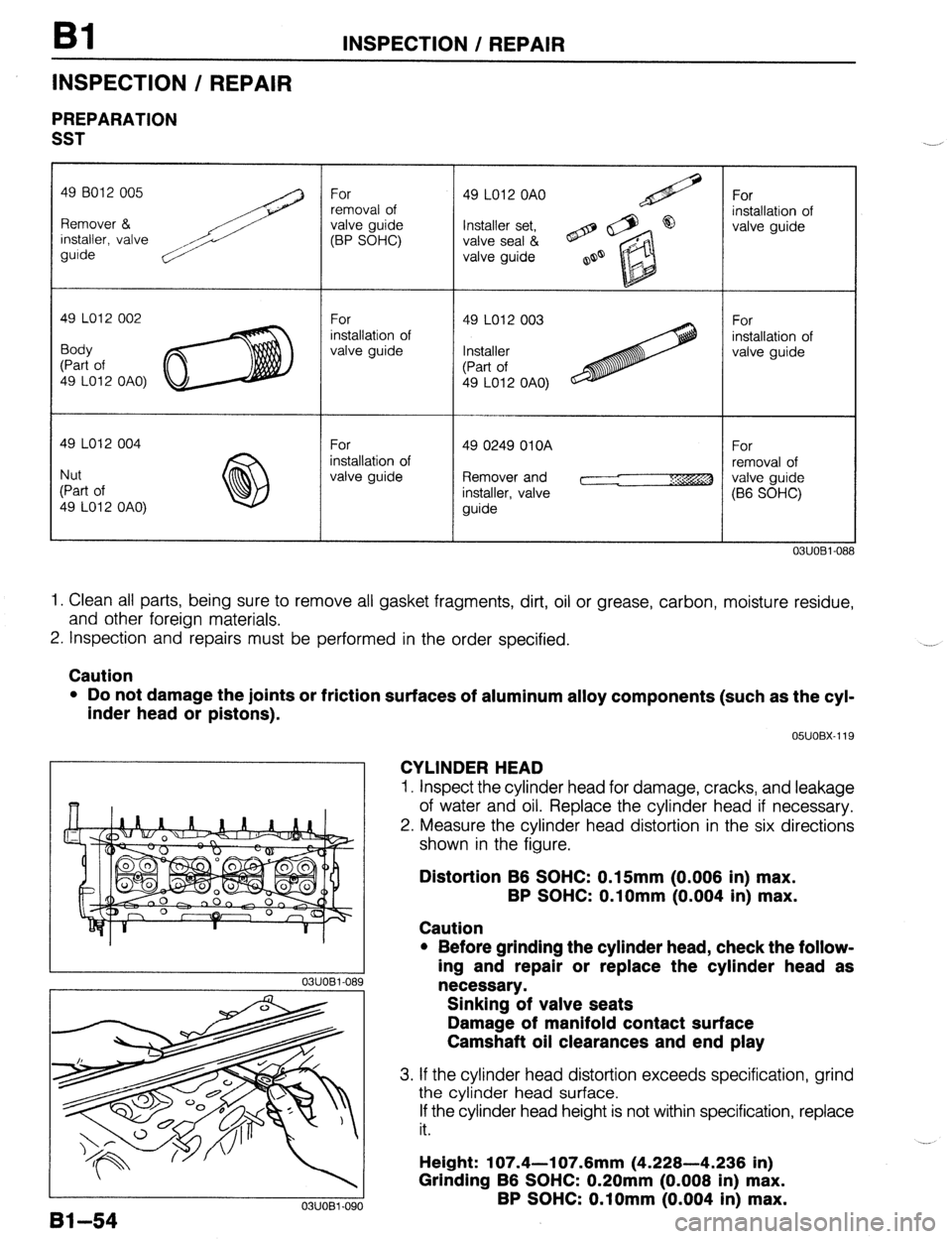
PREPARATION
SST
49 LO12 OAO)
Remover and
03UOBi-08
1. Clean all parts, being sure to remove all gasket fragments, dirt, oil or grease, carbon, moisture residue,
and other foreign materials.
2. Inspection and repairs must be performed in the order specified. .__a
Caution
l Do not damage the joints or friction surfaces of aluminum alloy components (such as the cyl-
inder head or pistons).
81-54
03UOBl-090 05UOBX-119
CYLINDER HEAD
1. Inspect the cylinder head for damage, cracks, and leakage
of water and oil. Replace the cylinder head if necessary.
2. Measure the cylinder head distortion in the six directions
shown in the figure.
Distortion B6 SOHC: 0.15mm (0.006 in) max.
BP SOHC: O.lOmm (0.004 in) max.
Caution
l Before grinding the cylinder head, check the follow-
ing and repair or replace the cylinder head as
necessary.
Sinking of valve seats
Damage of manifold contact surface
Camshaft oil clearances and end play
3. If the cylinder head distortion exceeds specification, grind
the cylinder head surface.
If the cylinder head height is not within specification, replace
it.
Height: 107.4-l 07.6mm (4.228-4.236 in)
Grinding B6 SOHC: 0.20mm (0.008 in) max.
BP SOHC: O.lOmm (0.004 in) max.
Page 186 of 1164

I32 INSPECTION / REPAIR
INSPECTION / REPAIR
PREPARATION
SST
49 6012 005 49 6012 005
Remover & Remover &
installer, valve installer, valve
guide guide
49 LO12 002
Body
(Part of
49 LO12 OAO)
49 LO12 004
Nut
(Part of
49 LO12 OAO) For
removal of
valve guide
For
installation of
valve guide
For
installation of
valve guide 49 LO12 OAO
Installer set,
valve seal &
valve guide
49 LO12 003
Installer
(Part of
49 LO12 OAO) For
installation of
valve guide
For
installation of
valve guide
05UOBX-1
1. Clean all parts, being sure to remove all gasket fragments, dirt, oil or grease, carbon, moisture residue,
and other foreign materials.
2. Inspection and repairs must be performed in the order specified. -.,
Caution
l Do not damage the joints or friction surfaces of aluminum alloy components (such as the cyl-
inder head or pistons).
0311082-162
03UOB2-70 OWOBX-119
CYLINDER HEAD
1, Inspect the cylinder head for damage, cracks, and leakage
of water and oil. Replace the cylinder head if necessary.
2. Measure the cylinder head distortion in the six directions
shown in the figure.
Distortion: O.lOmm (0.004 in) max.
Cautlon
l Before grinding the cylinder head, check the follow-
ing and repair or replace the cylinder head as
necessary.
Sinking of valve seats
Damage of manifold contact surface
Camshaft oil clearances and end play
3. If the cylinder head distortion exceeds specification, grind
the cylinder head surface.
If the cylinder head height is not within specification, replace
it. Height: 133.8-l 34.0mm (5.268-5.276
in)
Grinding: O.lOmm (0.004 in) max.
62-64
Page 721 of 1164

FRONT SUSPENSION (STRUT) R
DIRECTION INDICATOR
LOWER BRACKET
i’
I
I I
LOWER BRACKET
03UORX-02; 5. Apply the rubber lubricant to the bound stopper and the
upper spring seat contact surfaces.
6. Install the rubber spring seat and the upper spring seat.
7. Install the thrust bearing.
8. install the mounting block, facing the direction indicator as
shown in the figure.
9. Loosely tighten the mounting block nut.
10. Carefully loosen, and remove the
SST.
Caution
l Verify that the coil spring is correctly seated in the
upper and lower seats.
11. Secure the mounting block in a vise.
12. Tighten the mounting block nut to the specified torque.
Tightening torque:
78-l 10 N-m (8.0-l 1.2 m-kg, 58-81 ft-lb)
13. Install the cap over the nut.
R-l 5
Page 835 of 1164

FLOORMAT S
FLOORMAT
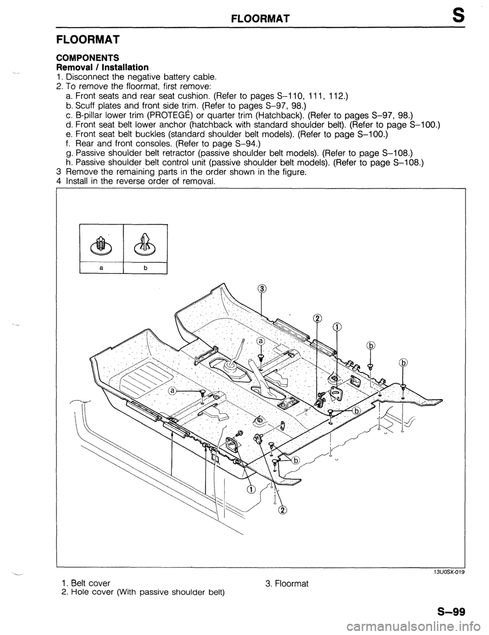
COMPONENTS
Removal / Installation
1. Disconnect the negative battery cable.
2. To remove the floormat, first remove:
a. Front seats and rear seat cushion. (Refer to pages S-l 10, 111, 112.)
b. Scuff plates and front side trim. (Refer to pages S-97, 98.)
c. B-pillar lower trim (PROTEGE) or quarter trim (Hatchback). (Refer to pages S-97, 98.)
d. Front seat belt lower anchor (hatchback with standard shoulder belt). (Refer to page S-100.)
e. Front seat belt buckles (standard shoulder belt models). (Refer to page S-100.)
f. Rear and front consoles. (Refer to page S-94.)
g. Passive shoulder belt retractor (passive shoulder belt models). (Refer to page S-108.)
h. Passive shoulder belt control unit (passive shoulder belt models). (Refer to page S-108.)
3 Remove the remaining parts in the order shown in the figure.
4 Install in the reverse order of removal.
1. Belt cover
2. Hole cover (With passive shoulder belt) 3. Floormat
s-99