open gas tank MAZDA PROTEGE 1992 Workshop Manual
[x] Cancel search | Manufacturer: MAZDA, Model Year: 1992, Model line: PROTEGE, Model: MAZDA PROTEGE 1992Pages: 1164, PDF Size: 81.9 MB
Page 283 of 1164

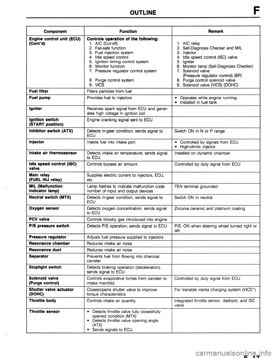
OUTLINE
Component Function Remark
Engine control unit (ECU) Controls operation of the following:
(Cont’d)
1. A/C (Cut-off) 1. A/C relay
2. Fail-safe function 2. Self-Diagnosis Checker and MIL
3. Fuel injection system 3. Injector
4. idle speed control 4. Idle speed control (ISC) valve
5. Ignition timing control system 5. Igniter
6. Monitor function 6. Monitor lamp (Self-Diagnosis Checker)
7. Pressure regulator control system 7. Solenoid valve
(Pressure regulator control) (BP)
8. Purge control system 8. Purge control solenoid valve
9. VICS 9. Solenoid valve (WCS) (DOHC) Fuel filter
Filters particles from fuel Fuel pump
Provides fuel to injectors l Operates while engine running l Installed in fuel tank Igniter
Receives spark signal from ECU and gener-
ates high voltage in ignition coil Ignition switch
Engine cranking signal sent to ECU (START position)
Inhibitor switch (ATX)
Detects in-gear condition; sends signal to Switch ON in N or P range
ECU Injector
Intake air thermosensor
Idle speed control (ISC)
valve
Main relay
(FUEL INJ relay)
MIL (Malfunction
indicator lamp)
Neutral switch (MTX)
Oxygen sensor
PCV valve
P/S pressure switch
Pressure regulator
Resonance chamber
Resonance duct
Separator
Stoplight switch
Solenoid valve
(Purge control)
Shutter valve actuator
(DOHC)
Throttle body
Throttle sensor
Injects fuel into intake port l Controlled by signals from ECU
l High-ohmic injector
Detects intake air temperature; sends signal Installed on dynamic chamber
to ECU
Controls bypass air amount Controlled by duty signal from ECU
Supplies electric current to injectors, ECU,
etc.
Lamp flashes to indicate malfunction code
number of input and output devices
Detects in-gear condition; sends signal to
ECU
Detects oxygen concentration; sends signal
to ECU
Controls blowby gas introduced into engine
Detects P/S operation; sends signal to ECU
Adjusts fuel pressure supplied to injectors
Reduces intake air noise
Reduces intake air noise
Prevents fuel from flowing into charcoal
canister
Detects braking operation (deceleration),
sends signal to ECU
Controls evaporative fumes from canister to
intake manifold
Closes/opens shutter valve to improve
torque characteristics
Controls intake air quantity
l Detects throttle valve fully closed/fully
opened condition (MTX) TEN terminal grounded
Switch ON in neutral
Zirconia ceramic and platinum coating
P/S: ON when steering wheel turned right or
left
Controlled by duty signal from ECU
For Variable inertia charging system (VICS*)
Integrated throttle sensor, dashpot, and ISC
valve
l Detects throttle valve opening angle
(A-W
l Sends signals to ECU
F-l 7
Page 389 of 1164

FUEL SYSTEM F
FUEL TANK
Removal / Inspection / Installation
Warning
l Before performing the following operation, release the fuel pressure from the fuel system to
reduce the possibility of injury or fire. (Refer to page F-121 .)
l When removing the fuel tank, keep sparks, cigarettes, and open flames away from it.
l Before repair the fuel tank, clean it throughly with steam to remove all explosive gas.
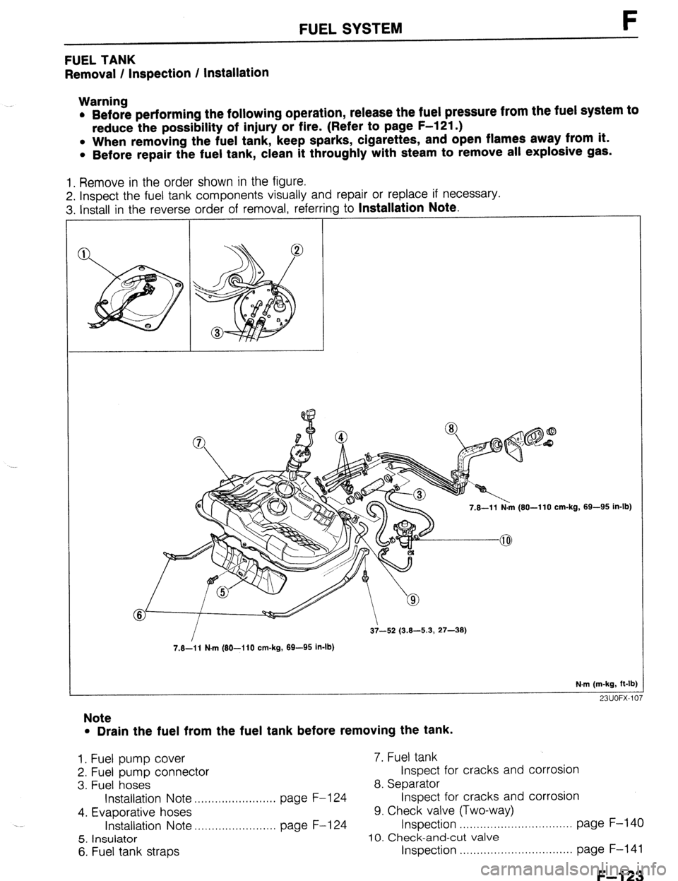
1. Remove in the order shown in the figure.
2. Inspect the fuel tank components visually and repair or replace if necessary.
3. Install in the reverse order of removal, referring to
Installation Note.
7.8-l 1 N.m (80-l 10 cm-kg,
7.8-i 1 N-m (80-I 10 cm-kg, 89-95 in-lb) 69-95 in-lb)
N.m (m-kg, ft-lb]
23UOFX-107
Note
l Drain the fuel from the fuel tank before removing the tank.
1. Fuel pump cover 7. Fuel tank
2. Fuel pump connector Inspect for cracks and corrosion
3. Fuel hoses 8. Separator
Installation Note . ..., I .I,,,,I,I,.,.I.,,. page F-l 24 Inspect for cracks and corrosion
4. Evaporative hoses 9. Check valve (Two-way)
Installation Note ,..,..,................. page F-l 24 Inspection . . . . . . . . . . . . . . . . . . . . . . . . . . . . . . . . . page F-140
5. Insulator 10. Check-and-cut valve
6. Fuel tank straps Inspection . . . . . . . . . . . . . . . . . . . . . . . . . . . page F-141
F--l 23
Page 1050 of 1164

PARTS INDEX
I
CRANKSHAFT.. ....................................
I31 -64
CYLINDER BLOCK .............................. 61-60
CYLINDER HEAD..
............................... 81-54
CYLINDER HEAD GASKET .................
Bl-16
DRIVE BELT(S). ...................................... 81-5
FRONT OIL SEAL ................................ 81-23
HLA .............................................. Bl-7,20,60
OIL JET ................................................ 81-61
PISTON.. ...............................................
Bl-62
PISTON PIN..
........................................ 81-62
PISTON RING
....................................... 81-62
REAR
OIL SEAL..
................................. 81-25
TENSIONER, IDLER ............................. Bl-65
TENSIONER
SPRING ...........................
Bl-65
TIMING BELT ..................................
Bl-12,65
TIMING BELT PULLEY ........................
Bl-65
VALVE MECHANISM ........................... Bl-55
ENGINE
(BP DOHC) .................................... B2-2
CAMSHAFT ..........................................
82-58
CAMSHAFT PULLEY ...........................
B2-65
CONNECTING ROD..
........................... 82-63
CRANKSHAFT ......................................
B2-64
CYLINDER BLOCK ..............................
82-60
CYLINDER
HEAD.. ............................... B2-54
CYLINDER HEAD GASKET .................
82-16
DRIVE
BELTS.. .......................................
B2-5
FRONT
OIL SEAL ................................
82-26
H LA ..............................................
OIL JET .......................... B2-7iyL;;
......................
PISTON .................................................
B2-62
PISTON PIN ..........................................
82-62
PISTON RING..
..................................... 82-62
REAR OIL SEAL ................................... B2-28
TENSIONER, IDLER ............................. B2-65
TENSIONER SPRING ........................... B2-65
TIMING
BELT.. ................................
B2-12,65
TIMING BELT PULLEY ........................ 82-65
VALVE MECHANISM ........................... 82-55
ENGINE CONTROL UNIT (ECU) ............... F-149
ENGINE COOLANT
........................................ E-5
ENGINE OIL.. .................................................
D-7
ENGINE OIL FILTER.. .................................... D-8
’ EXHAUST SYSTEM. ...................................
F-136
EXTRACTOR CHAMBER .............................. S-53
F
FAN MOTOR (COOLING FAN). ................... E-14
FAN RELAY (COOLING FAN). ..................... E-18
FLASHER UNIT ............................................
T-17
FLOORMAT ..................................................
S-99
FLYWHEEL ..................................................
H-18
FRONT AXLE .................................................
M-4
FRONT BRAKE ............................................
P-l 8
FRONT BUMPER ......................................... S-39
FRONT DOOR ................................................
S-8
FRONT DOOR LOCK AND OPENER ..........
S-13
PI-2
FRONT FENDER PANEL ............................... S-7
FRONT LOWER ARM .................................. R-16
FRONT SHOCK ABSORBER AND SPRING R-11
FRONT SIDE WINDOW REGULATOR AND
GLASS ........................................................ S-10
FRONT STABILIZER..
................................... R-l 8
FRONT SUSPENSION .................................. R-l 0
FUEL FILLER LID AND OPENER..
.............. S-37
FUEL FILTER .............................................. F-l 24
FUEL GAUGE SENDER UNIT ..................... T-73
FUEL PUMP ............................................... F-125
FUEL TANK
................................................ F-123
FUSE AND JOINT BOX.. .............................. T-12
H
HEADLIGHT AND
FRONT COMBINATION LIGHT..
................ T-41
HEADLIGHT RELAY ..................................... T-l 8
HEADLINER ................................................. S-89
HEATER CONTROL UNIT.. ......................... U-26
HEATER UNIT
.............................................. U-21
HIGH-MOUNT STOPLIGHT
.......................... T-45
HIGH-TENSION LEAD ................................. G-l 7
HOOD ............................................................. S-5
HORN T-88
...........................................................
HORN RELAY
.......................................... T-18,88
.__. ’
I I
IGNITER .......................................................
G-23
IGNITION COIL.. .......................................... G-19
INJECTOR .................................................. F-l 31
INSTRUMENT CLUSTER
AND SPEEDOMETER CABLE
.................... T-69
INTAKE MANIFOLD ................................... F-113
INTERIOR LAMP ..................................... T-52,53
ISC VALVE.. ................................................ F-l 16
J
JOINT SHAFT (FRONT AXLE) .................... M-18
L
LATERAL LINK AND TRAILING LINK.. ....... R-26
LICENSE PLATE LIGHT.. ............................. T-47
i
M
I
---
MAIN RELAY (FUEL INJ. RELAY). ............ F-172
MANUAL STEERING ..................................... N-4
MANUAL TRANSAXLE (F5M-R). .................. Jl-2