washer fluid MAZDA PROTEGE 1992 Workshop Manual
[x] Cancel search | Manufacturer: MAZDA, Model Year: 1992, Model line: PROTEGE, Model: MAZDA PROTEGE 1992Pages: 1164, PDF Size: 81.9 MB
Page 20 of 1164

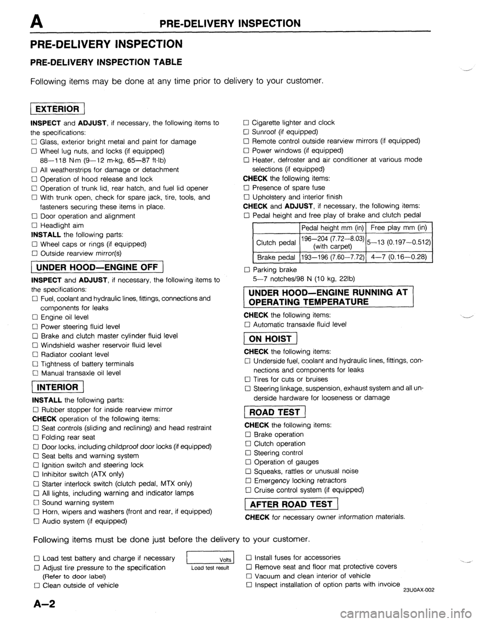
PRE-DELIVERY INSPECTION
PRE-DELIVERY INSPECTION
PRE-DELIVERY INSPECTION TABLE
Following items may be done at any time prior to delivery to your customer.
INSPECT and ADJUST, if necessary, the following items to
the specifications:
0 Glass, exterior bright metal and paint for damage
Cl Wheel lug nuts, and locks (if equipped)
88-118 N.m (9-12 m-kg, 65-87 ft-lb)
q All weatherstrips for damage or detachment
0 Operation of hood release and lock
0 Operation of trunk lid, rear hatch, and fuel lid opener
Cl With trunk open, check for spare jack, tire, tools, and
fasteners securing these items in place.
Cl Door operation and alignment
Cl Headlight aim
INSTALL the following parts:
Cl Wheel caps or rings (if equipped)
q Outside rearview mirror(s)
1 UNDER HOOD-ENGINE OFF )
INSPECT and ADJUST, if necessary, the following items to
the specifications:
0 Fuel, coolant and hydraulic lines, fittings, connections and
components for leaks
Cl Engine oil level
0 Power steering fluid level
0 Brake and clutch master cylinder fluid level
El Windshield washer reservoir fluid level
Cl Radiator coolant level
Cl Tightness of battery terminals
Cl Manual transaxle oil level
riizmiq
INSTALL the following parts:
Cl Rubber stopper for inside rearview mirror
CHECK operation of the following items:
0 Seat controls (sliding and reclining) and head restraint
Cl Folding rear seat
0 Door locks, including childproof door locks (if equipped)
Seat belts and warning system
Cl Ignition switch and steering lock
0 Inhibitor switch (ATX only)
U Starter interlock switch (clutch pedal, MTX only)
Cl All lights, including warning and indicator lamps
Cl Sound warning system
Cl Horn, wipers and washers (front and rear, if equipped)
0 Audio system (if equipped) 0 Cigarette lighter and clock
0 Sunroof (if equipped)
II Remote control outside rearview mirrors (if equipped)
Cl Power windows (if equipped)
q Heater, defroster and air conditioner at various mode
selections (if equipped)
CHECK the following items:
Cl Presence of spare fuse
0 Upholstery and interior finish
CHECK and ADJUST, if necessary, the following items:
0 Pedal height and free play of brake and clutch pedal
Pedal height mm (in) Free play mm (in)
0 Parking brake
5-7 notches/98 N (10 kg, 22lb)
UNDER HOOD-ENGINE RUNNING AT
OPERATING TEMPERATURE
CHECK the following items:
q Automatic transaxle fluid level
[I
CHECK the following items:
Cl Underside fuel, coolant and hydraulic lines, fittings, con-
nections and components for leaks
0 Tires for cuts or bruises
0 Steering linkage, suspension, exhaust system and all un-
derside hardware for looseness or damage
[I
CHECK the following items:
0 Brake operation
0 Clutch operation
Cl Steering control
Cl Operation of gauges
q Squeaks, rattles or unusual noise
Cl Emergency locking retractors
0 Cruise control system (if equipped)
1 AFTER ROAD TEST (
CHECK for necessary owner information materials.
Following items must be done just before the delivery to your customer.
q Load test battery and charge if necessary
1 Volts 1 0 Install fuses for accessories
i.. _
0 Adjust tire pressure to the specification
Load test result cl Remove seat and floor mat protective covers
(Refer to door label) 0 Vacuum and clean interior of vehicle
0 Clean outside of vehicle q Inspect installation of option parts with invoice
23UOAX-002
A-2
Page 28 of 1164

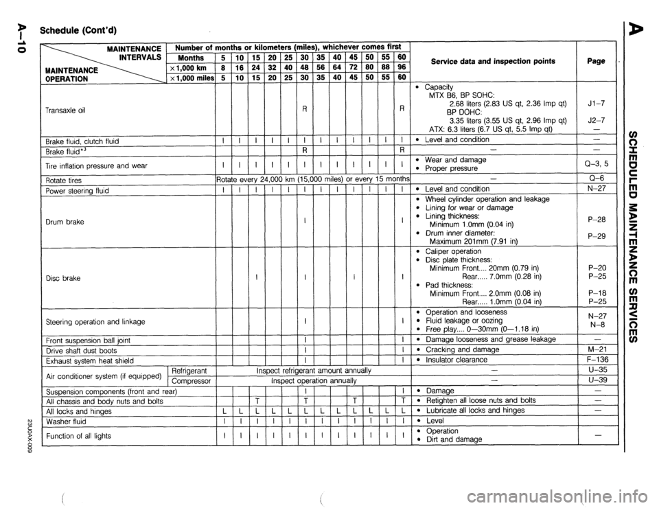
7 Schedule (Cont’d)
rile
iii
48
30
-
R
I
R !rs
25
40
25
-
-i- , whichever comes first
OPERATION MAINTENANCE Number of m
INTERVALS Months
x 1,000 km
x 1,000 miles
ii
is
G
-
i-
-
-
I
5-
T
-
-
-
-
-
-
- ii
z
ro
-
I-
-
-
I
- 45
72
45
-
-i-
-
-
I
-
ry 15 month:
I I I
A
t
A
j
milt Service data and inspection points Page
l Capacity
MTX B6, BP SOHC:
2.68 liters (2.83 US qt, 2.36 Imp qt)
BP DOHC
3.35 liters (3.55 US qt, 2.96 Imp qt)
ATX: 6.3 liters (6.7 US qt, 5.5 Imp qt)
l Level and condition
- Jl-7
J2-7
- Transaxle oil
l Wear and damaae -i- -i- -i- -
Brake fluid, clutch fluid
Brake fluid*3 -
Q-3, 5
Q-6
N-27
P-28
P-29 I I
- I
1,oo
-i
-
-
-
-
-
-
- I
G
T
-
-
-
-
-
-
- I
15,(
I Tire inflation pressure and wear l Proper pressure-
-
l Level and condition
l Wheel cylinder operation and leakage l Lining for wear or damage l Lining thickness:
Minimum 1 .Omm (0.04 in)
l Drum inner diameter. 3s) or f
I I
I
:t r
- Rotate tires
Power steering fluid
Drum brake ? every
I I
Disc brake I I
Maximum 201mm (7.91 in)
l Caliper operation l Disd plate thickness:
Minimum Front.... 20mm (0.79 in)
Rear . . . . . 7.0mm (0.28 in)
l Pad thickness:
Minimum Front.... 2.0mm (0.08 in) P-20
P-25
P-l 8
P-25
N-27
N-8 Rear . . . . . 1 .Omm (0.04 in)
l Operation and looseness l Fluid leakage or oozina
l Free play.... O--3OmmjO-1.18 in)
l Damage looseness and grease leakage
l Cracking and damage
l Insulator clearawp .-v
-
Steering operation and linkage
I
-i-
-I-
-i- Front suspension ball joint
Drive shaft dust boots
Exhaust system heat shield
Air conditioner system (if equipped) Refrigerant
Compressor
Suspension components (front and rear)
All chassis and body nuts and bolts
All locks and hinaes
Washer fluid -
M-21
F-136
u-35
u-39
-
- IY efrigerant amount ann
*. I# mspec
Inspect operation annualry -
l Damaae
l Retighten all loose nuts and bolts
l Lubricate all locks and hinges
l Level
l ODeration - Function of all lights l !%t and damage -
Page 676 of 1164

P CONVENTIONAL BRAKE SYSTEM
Removal / Inspection / Installation
1. Remove in the order shown in the figure.
2. Inspect all parts and repair or replace as necessary.
3. install in the reverse order of removal.
4. After installation, check and adjust the pedal height and free play if necessary.
r
20-34 (2.0-3.5, 14-25)
N-m (m-kg, ft-lb)
23UOPX-01
1. Cotter pin
2. Clevis pin
3. Nut
4. Lock washer
5. Bolt 6. Return spring 9. Bushing
Inspect for wear and damage Inspect for wear
7. Pedal 10. Bushing
Inspect for bending and Inspect for wear
damage 11. Pad
8, Pedal pipe Inspect for wear
MASTER CYLINDER
Removal / Installation
1. Remove in the order shown in the figure, referring to Removal Note.
2. Install in the reverse order of removal, referring to Installation Note.
3. After installation. add brake fluid. bleed air, and check for fluid leakage.
1.3-2.2, 9.4-16)
9.6-16 (1.0-1.6, 7.2-12)
13-22 (1.3-2.2, 9.4-l
N.m (m-kg, ft-lb)
23UOPX-01
1. Connector 4. Nut and washer
2. Brake pipe 5. Master cylinder
Removal Note . . . . . . . . . . . . . . . . . . . . . . . . . . . . . page P-i 1 Installation Note . . . . . . . . . . . . . . . . . . . . . . . . . . page P-l 1
Installation Note . . . . . . . . . . . . . . . . . . . . . . . . . . page P-l 1 Disassembly / Assembly /
3. Hose (MTX) Inspection . . . . . . . . . . . . . . . . . . . . . . . . . . . . . . . page P-l 2
P-l 0
Page 918 of 1164

T
I WARNING SYSTEM
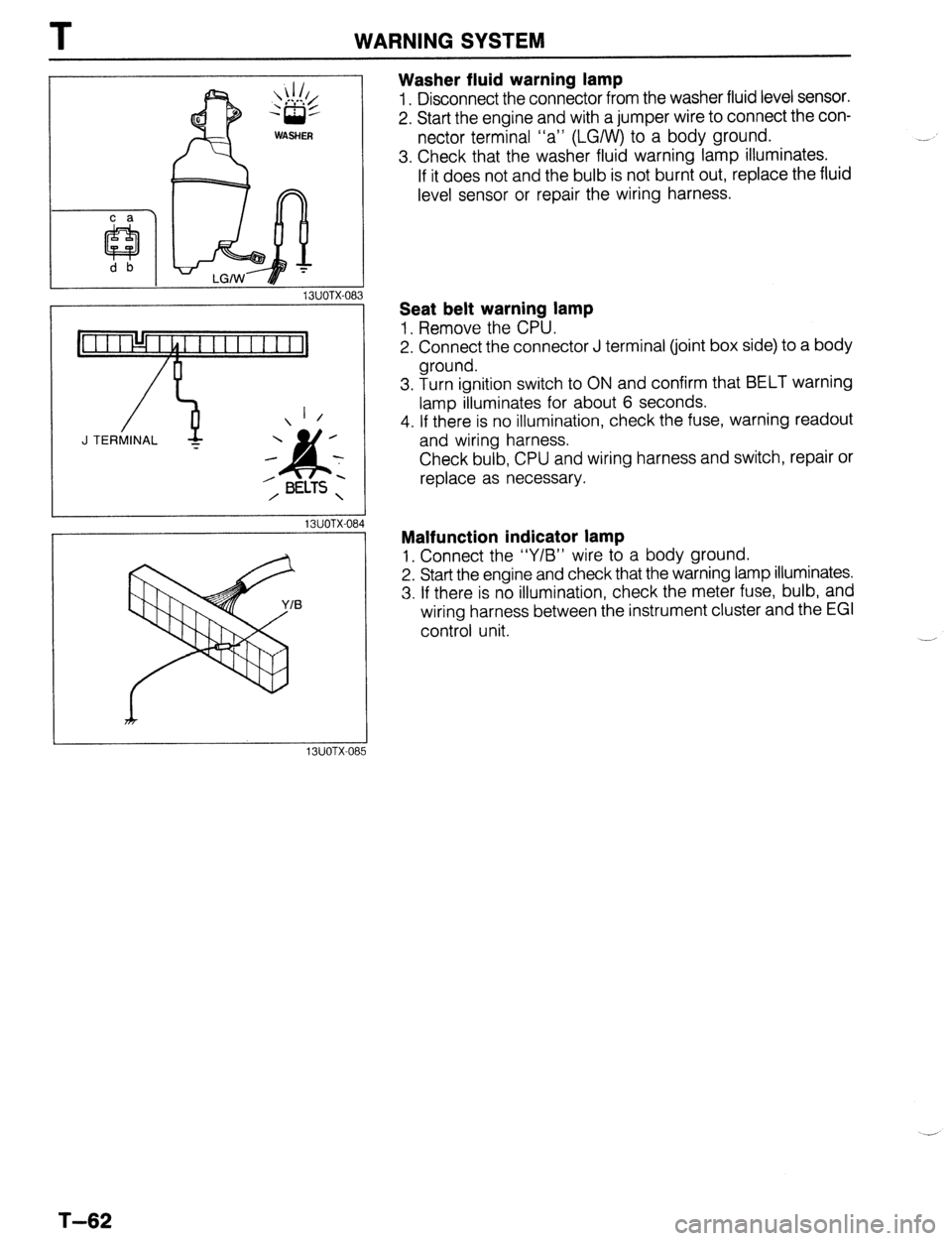
Washer fluid warning lamp
1. Disconnect the connector from the washer fluid level sensor.
2. Start the engine and with a jumper wire to connect the con-
nector terminal “a” (LGIW) to a body ground.
3. Check that the washer fluid warning lamp illuminates.
If it does not and the bulb is not burnt out, replace the fluid
level sensor or repair the wiring harness.
13UOTX-08
_-
1 /
J TERMINAL -
13UOTX-08
13UOTX-08
Seat belt warning lamp
1, Remove the CPU.
2. Connect the connector J terminal (joint box side) to a body
ground.
3. Turn ignition switch to ON and confirm that BELT warning
lamp illuminates for about 6 seconds.
4. If there is no illumination, check the fuse, warning readout
and wiring harness.
Check bulb, CPU and wiring harness and switch, repair or
replace as necessary.
Malfunction indicator lamp
1, Connect the “Y/B” wire to a body ground.
2. Start the engine and check that the warning lamp illuminates.
3. If there is no illumination, check the meter fuse, bulb, and
wiring harness between the instrument cluster and the EGI
control unit.
T-62
Page 1051 of 1164

PARTS
DIFFERENTIAL ..................................... Jl-52
SHIFT MECHANISM ............................. Jl-56
TRANSAXLE ............................................ Jl-8
TRANSAXLE OIL .................................... Jl-7
MANUAL TRANSAXLE (G5M-R) .................. J2-2
DIFFERENTIAL ..................................... J2-43
SHIFT MECHANISM ............................. J2-46
TRANSAXLE.. .......................................... J2-8
TRANSAXLE OIL .................................... J2-7
MOLDING, PROTECTOR, GARNISH ...........
S-42
BELTLINE MOLDING ............................. S-48
REAR WINDOW MOLDING.. ............. S-43,44
ROOF MOLDING.. .................................. S-46
SIDE PROTECTOR ................................. S-49
UPPER WINDSHIELD MOLDING,
A-PILLAR GARNISH ............................ S-42
NEUTRAL SWITCH (MTX) . . . . . . . . . . . . . . . . . . . . . . . . . . F-l 73
0
1
\_ OIL COOLER (ENGINE). ................................ D-8
OIL PAN (ENGINE) ........................................ D-9
OIL PUMP (ENGINE) ................................... D-l 3
..................................... F-l 71
OXYGEN SENSOR
P
PARKING BRAKE ......................................... P-31
PARKING BRAKE CABLE ............................ P-32
PARKING BRAKE LEVER ............................ P-33
PARKING BRAKE SHOE ............................. P-31
PASSIVE SHOULDER BELT SYSTEM.. ..... S-103
DOOR CATCH SWITCH ....................... S-l 07
LIMIT SWITCH ...................................... S-l 07
PASSIVE SHOULDER BELT MOTOR.. S-106
SPEED SENSOR ................................... S-l 07
WARNING SWITCH .............................. S-l 07
PCV VALVE ................................................
POWER BRAKE UNIT ‘;--=I;;
..................................
POWER DOOR LOCK SYSTEM ................... S-23
DOOR LOCK CONTROL.. ...................... S-26
DOOR LOCK SWITCH.. .......................... S-26
DOOR LOCK TIMER AND RELAY.. ....... S-26
POWER STEERING.. .................................... N-23
POWER STEERING FLUID .......................... N-27
POWER STEERING OIL PUMP.. ................. N-37
POWER STEERING PRESSURE SWITCH . . F-l 73
POWER WINDOW SYSTEM.. .......................
S-27
MAIN POWER WINDOW SWITCH.. .......
S-31
POWER WINDOW MOTOR.. ..................
S-32
POWER WINDOW SUB-SWITCH ........... S-32
PRESSURE REGULATOR (FUEL). ............. F-l 29 . . . . . . . . , . . . . . , . RADIATOR CAP .............................................
E-7
RADIATOR GRILLE,
I
LOWER GRILLE MOLDING ....................... S-51 fl
RADIATOR THERMOSWITCH ...................... E-17 t
REAR AXLE ................................................. M-10
REAR BRAKE (DISC) ................................... P-23
REAR BRAKE (DRUM) ................................. P-28
REAR BUMPER ............................................ s-40
REAR COMBINATION LIGHT.. ....
REAR CROSSMEMBER ............................... R-29
REAR DOOR ................................................ S-l 5
REAR DOOR LOCK AND OPENER.. .
REAR FINISHER ........................................... s-52
REAR HATCH ............................................... s-20
REAR HATCH LOCK AND OPENER.. ......... S-22
REAR SHOCK ABSORBER AND SPRING.. R-21
REAR SIDE MARKER LIGHT ....................... T-48
REAR SIDE WINDOW REGULATOR AND . . . . . . . . .
AI .,.n
INDEX
Q
QUARTER WINDOW GLASS . . . . . . . . . . . . ..a........ S-62
R
RADIATOR . . . . . . . . . . . . . . . . . . . . . . . . . . . . . . . . . . . . . . . . . . . . . . . . . . . . . .
kiLA33 ........................................................ a-- I I
REAR SPEAKER ........................................... T-99
REAR SPOILER ............................................ s-41
REAR STABILIZER.. ..................................... R-27
REAR SUSPENSION .................................... R-20
REAR WINDOW GLASS ............................... S-63
REAR WINDOW DEFROSTER.. .................... T-74
REAR WINDOW DEFROSTER SWITCH ....... T-77
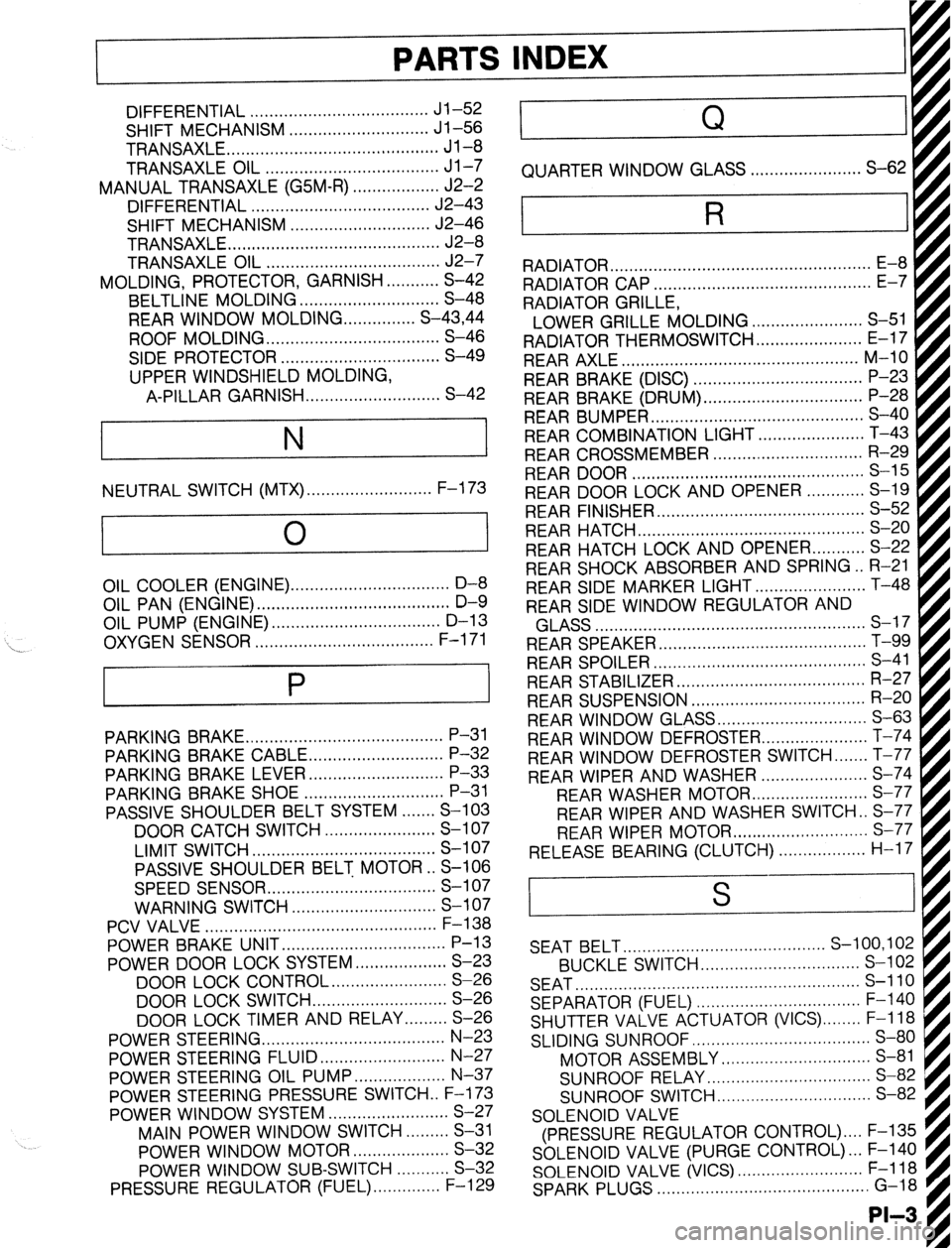
REAR WIPER AND WASHER ...................... S-74
REAR WASHER MOTOF
REAR WIPER AND WASHER SWITCH . . S-77
REAR WIPER MOTOR ............................ s-77
RELEASE BEARING (CLUTCH). . . . . . . . . . ..s..... H-17 I . . . . . . . . ...*. .*......*..
SEAT BELT.. ........................................ S-100,102
BUCKLE SWITCH.. ............................... S-l 02
SEAT ........................................................... s-110
SEPARATOR (FUEL) .................................. F-l 40
SHUTTER VALVE ACTUATOR (VICS) ........ F-l 18
SLIDING SUNROOF ..................................... S-80
MOTOR ASSEMBLY ............................... S-81
SUNROOF RELAY.. ................................ S-82
SUNROOF SWITCH.. .............................. S-82
SOLENOID VALVE
(PRESSURE REGULATOR CONTROL) .... F-135
SOLENOID VALVE (PURGE CONTROL). .. F-140
SOLENOID VALVE (VICS) .......................... F-l 18
SPARK PLUGS ............................................ G-18
-II__
Page 1162 of 1164

DIAGRAM Z
rl PARTS NAME
-
PA ,K
SECTION T
CIGARETTE LIGHTER ............................................
I-1
CIRCUIT OPENING RELAY ..............................
B-l&Pa
I CLUTCH
SWITCH .............................................. B-lc
CONDENSER ................................................. B-la.2a
CONDENSER FAN ..................................................
G
CONDENSER
FAN RELAY ....................................... G
COMBINATION
SWITCH .................................... E-l.2
COOLING FAN MOTOR .....................................
B-3,4
COOLING
FAN RELAY ........................................ B-3,4
COURTESY LAMP ................................................
l-3
CPU .................................................................... l-2
CRUISE CONTROL
MAIN SWITCH ........................... Q
CRUISE
CONTROL SWITCH .................................... Q
CRUISE CONTROL UNIT ......................................... Q 0 ACTUATOR ........................................................... Q
A/C RELAY ........................................................... G
t A/C SWITCH .........................................................
G
t AIRFLOW METER .......................................... B-lc,Pc
t ALTERNATOR .....................................................
A-2
I AUDIO SYSTEM .....................................................
J
@BACK-UP LIGHT .................................................. F-3
BACK-UP LIGHT SWITCH
..................................... F-3
I
BLOWER MOTOR ...................................................
G
h BLOWER SWITCH ..................................................
G
I BRAKE FLUID SWITCH ...........................................
C
BUCKLE SWITCH .............................................
l-2, S
@I DIAGNOSIS CONNECTOR .......................................
U
DIGITAL CLOCK
................................................... l-l
DIODE ..................................................................
G
DISTRIBUTOR ...............................................
B-l b,2b
DOOR CATCH SWITCH .......................................... S
DOOR
SPEAKER ..................................................... J
DOOR SWITCH ....................................................
l-2
DRL CONTROL UNIT ............................................
E-3
DRL RELAY .........................................................
E-3
ORL RESISTOR ....................................................
E-3
ENGINE CONTROL UNIT
.................................... B-1.2
ii@ FLASHER UNIT ....................................................
F-l
FRONT TURN LIGHT ............................................
F-l
FUEL METER
......................................................... C
FUEL
TANK UNIT .......................................... B-la,2a
HAZARD SWITCH ...............................................
F-l _
HEADLIGHT .....................................................
E-l.2
HEADLIGHT RELAY .............................................
E-2
h HIGH
MOUNT STOPLIGHT ....................................
F-2
h HOLD SWITCH .................................................. B-2c
4 HORN .................................................................
F-3
! HORN RELAY
...................................................... F-3
HORN SWITCH ....................................................
F-3
0 IC REGULATOR ..................................................
A-2
-L
T-S INDEX
PARTS NAME SECTION
IGNITER ........................................................ B-la,2a
IGNITION COIL ..............................................
B-la.2a
IGNITION KEY CYLINDER LAMP .............................
l-2
IGNITION KEY REMINDER SWITCH ........................ l-2
ILLUMINATION LAMP
A/C SWITCH ..................................................... l-4
AT SELECT
....................................................... l-4
AUDIO SYSTEM
................................................. l-4
BLOWER SWITCH .............................................
l-4
CIGARETTE LIGHTER
......................................... l-4
CRUISE CONTROL
MAIN SWITCH ....................... l-4
HAZARD SWITCH .............................................
l-4
INSTRUMENT CLUSTER
..................................... l-4
REAR WINDOW DEFROSTER SWITCH
................. l-4
INHIBITOR SWITCH .................................... A-l, B-2c
INJECTOR ....................................................
B-1 b,2b
INSTRUMENT CLUSTER ..........................................
C
INTERIOR & SPOT LAMP .......................................
l-2
ISC VALVE ...................................................
B-1 b,26
@ LICENSE PLATE LIGHT .........................................
E-4
LIMIT SWITCH .......................................................
S
481 MAGNETIC
CLUTCH .............................................. G
MAIN RELAY (FUEL INJ) ................................
B-la,Pa
@ NEUTRAL SWITCH ............................................
B-lc
@ OIL PRESSURE SWITCH ..........................................
C
OXYGEN SENSOR ......................................... B-la.2a
@ PANEL LIGHT CONTROL .......................................
l-4
PARKING BRAKE SWITCH ......................................
C
PASSIVE SHOULDER BELT CONTROL UNIT
.............. S
PASSIVE SHOULDER BELT
MOTOR .......................... S
POSITION LIGHT .................................................
E-4
POWER DOOR LOCK MOTOR
............................... K-2
POWER DOOR LOCK RELAY
................................. K-2
POWER DOOR LOCK SWITCH
.............................. K-2
POWER
OUTSIDE MIRROR ...................................... L
POWER OUTSIDE MIRROR MOTOR
.......................... L
POWER OUTSIDE MIRROR SWITCH .........................
L
POWER STEERING PRESSURE SWITCH ........... B-l b.2b
POWER WINDOW MAIN SWITCH .........................
K-l
POWER WINDOW MOTOR ...................................
K-l
POWER WINDOW SWITCH
.................................. K-l
@ REAR TURN LIGHT ..............................................
F-l
REAR SiDE MARKER LIGHT ..................................
E-4
REAR
SPEAKER ......................................................
J
REAR WASHER MOTOR ......................................
D-3
REAR WINDOW DEFROSTER
................................. I-1
REAR WINDOW DEFROSTER SWITCH ....................
I-1
REAR WIPER MOTOR
.......................................... D-3
REAR WIPER & WASHER SWITCH
........................ D-3
REFRIGERANT PRESSURE SWITCH
.......................... G
RESISTOR ASSEMBLY ............................................
G