cruise control MAZDA PROTEGE 1992 Workshop Manual
[x] Cancel search | Manufacturer: MAZDA, Model Year: 1992, Model line: PROTEGE, Model: MAZDA PROTEGE 1992Pages: 1164, PDF Size: 81.9 MB
Page 13 of 1164

CAUTION GI
CAUTION
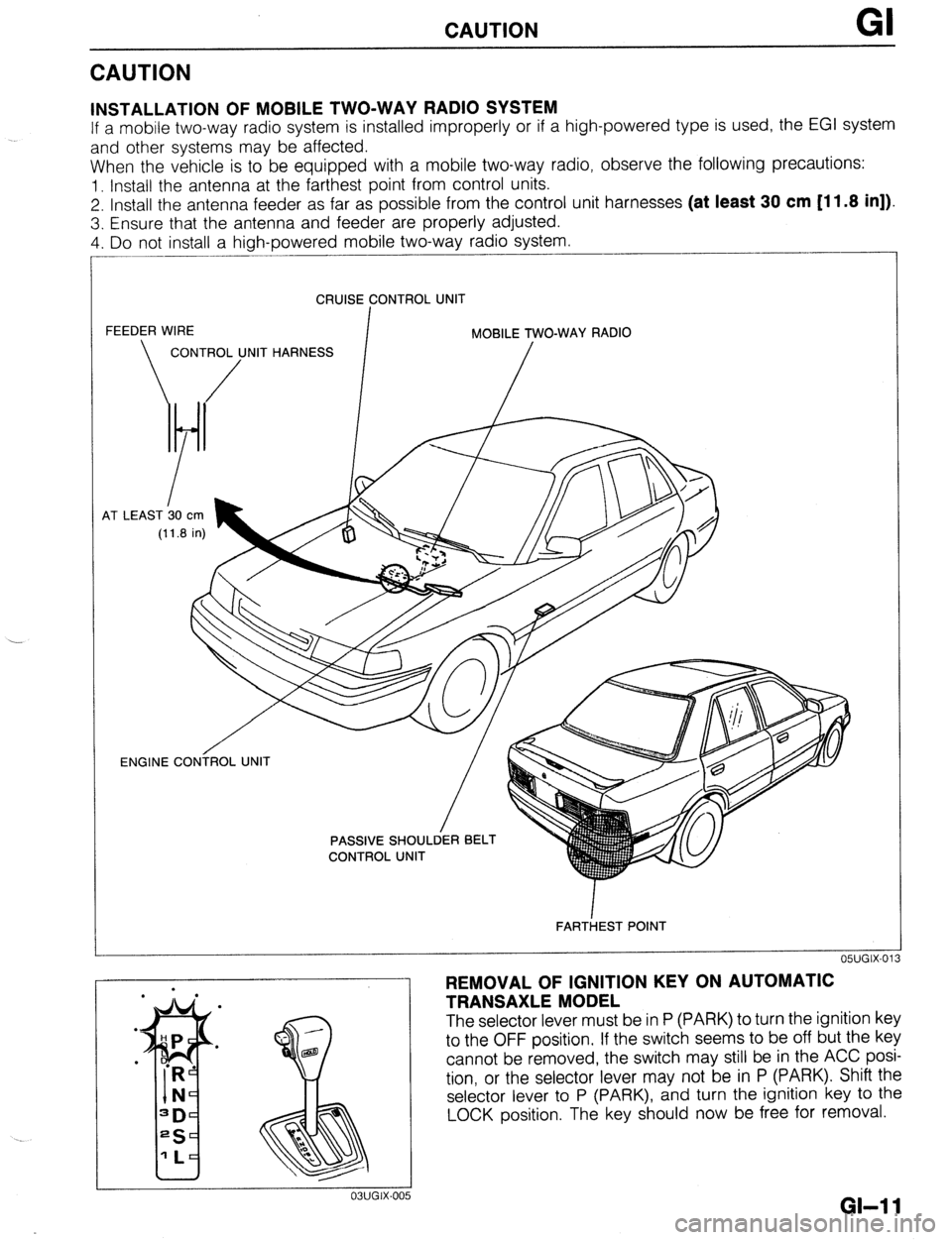
INSTALLATION OF MOBILE TWO-WAY RADIO SYSTEM
If a mobile two-way radio system is installed improperly or if a high-powered type is used, the EGI system
and other systems may be affected.
When the vehicle is to be equipped with a mobile two-way radio, observe the following precautions:
1. Install the antenna at the farthest point from control units.
2. Install the antenna feeder as far as possible from the control unit harnesses (at least 30 cm [11.8 in]).
3. Ensure that the antenna and feeder are properly adjusted.
4. Do not install a high-powered mobile two-way radio system.
CRUISE CONTROL UNIT
FEEDER WIRE
I MOBILE TWO-WAY RADIO
CONTROL UNIT HARNESS
/ /
4T LEAST b0
cm
(11.8 in)
OWGIX-013 ENGINE CONiROL UNIT
/
FARTiEST POINT
REMOVAL OF IGNITION KEY ON AUTOMATIC
TRANSAXLE MODEL
The selector lever must be in P (PARK) to turn the ignition key
to the OFF position. If the switch seems to be off but the key
cannot be removed, the switch may still be in the ACC posi-
tion, or the selector lever may not be in P (PARK). Shift the
selector lever to P (PARK), and turn the ignition key to the
LOCK position. The key should now be free for removal.
GI-1 1
Page 20 of 1164

PRE-DELIVERY INSPECTION
PRE-DELIVERY INSPECTION
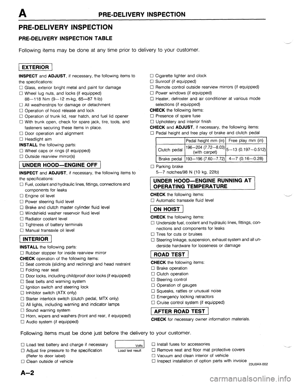
PRE-DELIVERY INSPECTION TABLE
Following items may be done at any time prior to delivery to your customer.
INSPECT and ADJUST, if necessary, the following items to
the specifications:
0 Glass, exterior bright metal and paint for damage
Cl Wheel lug nuts, and locks (if equipped)
88-118 N.m (9-12 m-kg, 65-87 ft-lb)
q All weatherstrips for damage or detachment
0 Operation of hood release and lock
0 Operation of trunk lid, rear hatch, and fuel lid opener
Cl With trunk open, check for spare jack, tire, tools, and
fasteners securing these items in place.
Cl Door operation and alignment
Cl Headlight aim
INSTALL the following parts:
Cl Wheel caps or rings (if equipped)
q Outside rearview mirror(s)
1 UNDER HOOD-ENGINE OFF )
INSPECT and ADJUST, if necessary, the following items to
the specifications:
0 Fuel, coolant and hydraulic lines, fittings, connections and
components for leaks
Cl Engine oil level
0 Power steering fluid level
0 Brake and clutch master cylinder fluid level
El Windshield washer reservoir fluid level
Cl Radiator coolant level
Cl Tightness of battery terminals
Cl Manual transaxle oil level
riizmiq
INSTALL the following parts:
Cl Rubber stopper for inside rearview mirror
CHECK operation of the following items:
0 Seat controls (sliding and reclining) and head restraint
Cl Folding rear seat
0 Door locks, including childproof door locks (if equipped)
Seat belts and warning system
Cl Ignition switch and steering lock
0 Inhibitor switch (ATX only)
U Starter interlock switch (clutch pedal, MTX only)
Cl All lights, including warning and indicator lamps
Cl Sound warning system
Cl Horn, wipers and washers (front and rear, if equipped)
0 Audio system (if equipped) 0 Cigarette lighter and clock
0 Sunroof (if equipped)
II Remote control outside rearview mirrors (if equipped)
Cl Power windows (if equipped)
q Heater, defroster and air conditioner at various mode
selections (if equipped)
CHECK the following items:
Cl Presence of spare fuse
0 Upholstery and interior finish
CHECK and ADJUST, if necessary, the following items:
0 Pedal height and free play of brake and clutch pedal
Pedal height mm (in) Free play mm (in)
0 Parking brake
5-7 notches/98 N (10 kg, 22lb)
UNDER HOOD-ENGINE RUNNING AT
OPERATING TEMPERATURE
CHECK the following items:
q Automatic transaxle fluid level
[I
CHECK the following items:
Cl Underside fuel, coolant and hydraulic lines, fittings, con-
nections and components for leaks
0 Tires for cuts or bruises
0 Steering linkage, suspension, exhaust system and all un-
derside hardware for looseness or damage
[I
CHECK the following items:
0 Brake operation
0 Clutch operation
Cl Steering control
Cl Operation of gauges
q Squeaks, rattles or unusual noise
Cl Emergency locking retractors
0 Cruise control system (if equipped)
1 AFTER ROAD TEST (
CHECK for necessary owner information materials.
Following items must be done just before the delivery to your customer.
q Load test battery and charge if necessary
1 Volts 1 0 Install fuses for accessories
i.. _
0 Adjust tire pressure to the specification
Load test result cl Remove seat and floor mat protective covers
(Refer to door label) 0 Vacuum and clean interior of vehicle
0 Clean outside of vehicle q Inspect installation of option parts with invoice
23UOAX-002
A-2
Page 47 of 1164

ON-VEHICLE MAINTENANCE Bl
I. Air hose assembly 1 I. Timing belt cover, upper
2. Resonance chamber 12. Timing belt
3. Accelerator cable Removal / Installation.. . . . . . . . . . . . . . . page Bl-12
Installation Note . . . . . . . . . . . . . . . . . . . . . . . . page BI-I9 13. Front exhaust pipe
4. Throttle cable (ATX)
14. Intake manifold bracket
Removal / Installation . . . . . . . . . . . . . . . . . . . . . Section K 15. Cylinder head bolt
5. Hoses Removal Note . . . . . . . . . . . . . . . . . . . . . . . . . . . page BI-18
Removal I Installation Note ..,............... below Installation Note . . . . . . . . . . . . . . . . . . . . . . . . page Bl-I9
6. Harnesses 16. Cylinder head
Removal I Installation Note....... page BI-I8 Disassembly . . . . . . . . . . . . . . . . . . . . . . . . . . . . page 61-43
7. Water bypass pipe nut
Inspection . . , . . . . . . . . . . . . . . . . . . . . . . . . . ., . . page BI -54
8. Drive belt Assembly . . . . . . . . . . . . . . . . . . . . . . . . . . . . . . . . . . page BI-79
9. Water pump pulley 17. Cylinder head gasket
10. Cylinder head cover
23UOBl-019
Removal / Installation note
Hoses
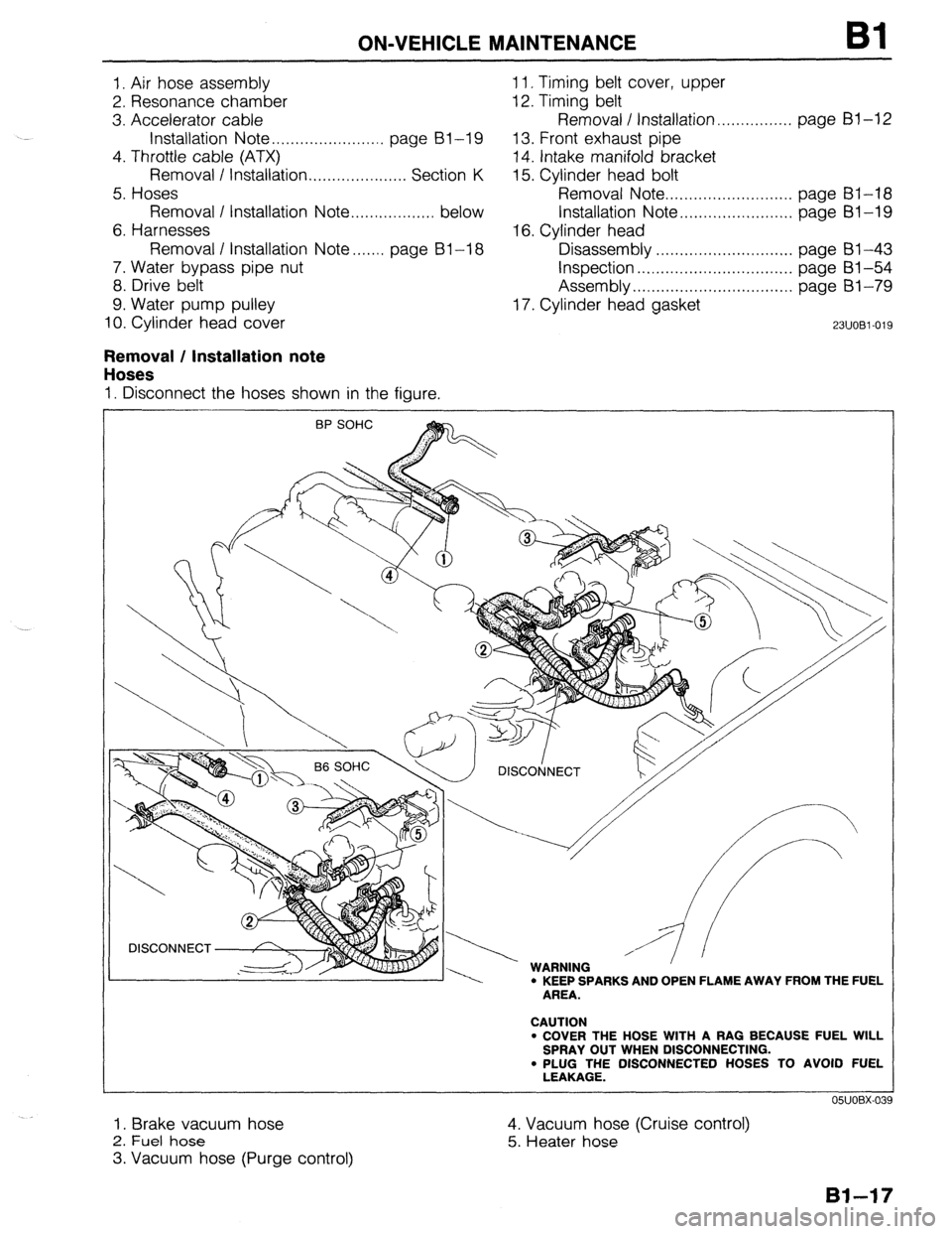
I. Disconnect the hoses shown in the figure.
\ / DlSCOtjNECT
, w I.,,, -----. WARNING ’ ’ ’ l KEEP SPARKS AND OPEN FLAME AWAY FROM THE FUEL
AREA.
CAUTION
l COVER THE HOSE WITH A RAG BECAUSE FUEL WILL
SPRAY OUT WHEN DISCONNECTING.
. PLUG THE DISCONNECTED HOSES TO AVOID FUEL
LEAKAGE.
I. Brake vacuum hose
2. Fuel hose
3. Vacuum hose (Purge control) 4. Vacuum hose (Cruise control)
5. Heater hose
Page 60 of 1164

Bl REMOVAL
Step 3
1. Disconnect the hoses shown in the figure.
BP SOHC
1. Brake vacuum hose
2. Fuel hose
Removal
Note . . . . . . . . . . . . . . . . . . . . . . . . . . . . . . . . . . .
Bl-30
05UOBX-078
03UOBi -050
below 3. Vacuum hose (Purge control)
4. Vacuum hose (Cruise control)
5. Heater hose
Removal Note ..,,,................................ below
Removal note
Fuel hose
Warning
l Keep sparks and open flame away from the fuel
area.
Caution
l Cover the hose with a rag because fuel will spray
out when disconnecting.
l Plug the disconnected hoses to avoid fuel leakage.
1. Disconnect the fuel hoses.
Heater hose
Caution
l Heater hose joint has O-rings and spacer.
l Do not lose them when removing.
1. Push the heater hose retainer and remove the heater hose.
Page 165 of 1164

REMOVAL
Step 3
1. Disconnect the hoses shown in the figure.
J”“DC-” I I
1. Fuel hose
3. Brake vacuum hose
Removal
Note . . . . . . . . . . . . . . . . . . . . . . . . . . . . . . . . . . . . .
below
4. Vacuum hose (Purge control)
2. Heater hose
Removal Note . . . . . . . . . . . . . , . . . . . . . . . . . .
05UOBX-078
0311082-052
. . . . .
below 5. Vacuum hose (Cruise control)
Removal note
Fuel hose
Warning
l Keep sparks and open flame away from the fuel
area.
Caution
l Cover the hose with a rag because fuel will spray
out when disconnecting.
l Plug the disconnected hoses to avoid fuel leakage.
1. Disconnect the fuel hoses.
Heater hose
Caution
l Heater hose joint has O-rings and spacer.
l Do not lose them when removing.
1. Push the heater hose retainer and remove the heater hose.
82-33
Page 231 of 1164

INSTALLATION
Step 4
I. Connect the hoses shown in the figure.
Caution Speedometer cable
1. Install the speedometer cable.
Exhaust pipe
1. Install the exhaust pipe and a gasket; then loosely tighten
the lock nuts.
2. Loosely tighten the bracket bolts.
3. Tighten the lock nuts.
Tightening torque:
31-46 N-m (3.2-4.7 m-kg, 23-34 ft-lb)
4. Tighten the bracket bolts.
Tightening torque:
37-52 N.m (3.8-5.3 m-kg, 27-38 ft-lb)
l Position the hose clamp in the original location on the hose, and squeeze the clamp lightly
with large pliers to ensure a good fit.
VACUUM HOSE
(CRUISE CONTROL) BRAKE, VACUUM HOSE 1 VACUUM HOSE
(PURGE CONTROL)
HEATER HOSE
FUE’L HOSE
03UOB2-14
B2-9:
Page 280 of 1164

F OUTLINE
A comparison of the new and previous models is as follows.
Engine Control Unit Terminal Relation Ship Chart
Connected to
Headlight switch Terminal
Connected to Terminal
New Previous New Previou
1H IU
Water thermosensor 2E 2Q
Diagnosis connector
(TEN terminal) / II 1 IK 1 1 Throttle sensor
Rear window defroster switch
I I 21 2K
Ground (California)
Main relay (Canada)
A/C relay
Vehicle speed sensor
P/S pressure switch
A/C switch
Blower control switch 1K 2H
IL 1J
1M --
1N 1P
10 IQ
1P 1s Distributor
(G-signal) [DOHC]
Intake air thermosensor
Solenoid valve
(Purge control)
Ground (Injector)
Ground (Output)
Ground (CPU) 2J 2G
2K 2P
20 2x
___
Stoplight switch 1Q 10
Ground (Input)
1 I I 1 ! 3D ! 2D
Cruise control main switch
1 lS / - II8cRalnardega,y
Throttle sensor
(Idle switch)
Distributor
(Ne-signal) 1T 1N
2A 2E
2B 20
2C 2N Solenoid valve
(VICS)
--.-- I_-
Solenoid valve
(Pressure regulator) [BP] 31 2s
-- -_
3M 2T
Airflow meter
Oxygen sensor
-
Fan switch 1 2D 1 IR 1 1 lniector (Nos. 2, 4) I 3v I 2v
23UOFX-01 I
F-l 4
Page 286 of 1164

F TROUBLESHOOTING GUIDE
TROUBLESHOOTING GUIDE
ENGINE CONTROL OPERATION CHART
Note
Input Device and Engine Conditions
l The data in this chart is for reference only.
INPUT DEVICES APPROX,- SENSORS
MATE TIME G& THROTTLE SENSOR
(BASED ON TRIBUTOR
WATER INTAKE
10-16°C, (G. OXYGEN AIRFLOW AIR
VT
POW
.50-6OOF
SIGNAL)” ;;;;;f- SENSOR METER
AMBIENT) (Ne-SIGNAL) THERMO- TERMINAL TERMINAL yE\MINAL
CONDITIONS SENSOR (ATX)
WX)
A
c
CRANKING
-COLD ENGINE Signal has Signal has Signal has Signal has Slgnal has Slgnal has
l COLD AIR zero no affect no effect no effect no effect no effect
no effect
. COLD COOLANT on ECU on ECU on ECU on ECU on ECU
on ECU
Cool to A A
COLD START
warm: Low volume Closed Closed
Closed
-FAST IDLE
One
Medium airflow: throttle: throttle:
l COLD AIR
minute
voltage High volt-
Low volt- Low volt- throttle.
Low volt-
* COLD COOLANT
(3.5” and :zo:o, ,,Pbove 1’,“,“$; a(ogi-O,8”) ;149&“) we W)
dropping) to high
(68OF)]:
COLD DRIVEAWAY voltage A
Above
-PART THROTTLE Two (O-0.9”) 2.3”
l COLD AIR minutes
l COLD COOLANT
v v ,,
Warm: Medi- Sensor Moderate II
WARM DRIVEAWAY
volume air-
-PART THROTTLE Three N&IGNAL um voitage hot:
flow: Low
l WARM AIR minutes Sends all Vvwrox switching l WARM COOLANT cylinders 0.7V and
from high to medium
Part Part
TDC signal dropping) voltage voltage
throttle: throttle.
)
A (0.9V) (1 .o-3.5”)
to ECU
.“~ Medium Medium
HOT CRUISE
s voltage voltage
Open
l WARM AIR G-
SIGNAL”’ to low (0.8-3.0”) (4.5-5.5”) throttle:
l WARM COOLANT High
Sends No. voltage
1 cylinder (0.1”) voltage
1 (battery
TDC (com-
1 I voltage)
HOT ACCELERATION pression)
-60% THROTTLE signal to
Moderate
ECU
to strong
High Cool lo warm
voltage ;$,“,” Of j-20-4OT
f t
HOT ACCELERATION
More’ than Hot: Low (0.9”) Low (-4-‘04”F)l: W,ds open
voltage 1.5-4.3v
throttle: Wide open
-WIDE OPEN
four voltage
High volt- throttle
THROTTLE (0.5-1.5V)
minutes (Below High
0.5”) age (Above
voltage (OV)
t 1 3.OV)
I,
A 1. /I
DECELERATION
-CLOSED THROTTLE
HOT CURB IDLE
-EXTENDED
HOT ENGINE
SHUTDOWN Low
voltage
(0”) Low Closed Closed
Closed
volume throttle: throttle.
throttle.
of airflow:
~~~~!$$ (Above Low Low
Low
voltage voltage
voltage
to low 3.OV) (0.2-0.N) (4.5-5 5V) (OV)
voltage
(0.75%
t t 1 0.25”)
r v 1 I I
Sensor
hot: Low
OFF OFF voltage
-
(0.1”) until OFF OFF OFF OFF
OFF
sensw
COOIS
._-
Page 288 of 1164

F TROUBLESHOOTING GUIDE
Output Devices and Engine Conditions
Note
. The data in this chart is for reference only.
INJECTOR
CONDITIONS
CRANKING
-COLD ENGINE
l COLD AIR l COLD COOLANT
COLD START
-FAST IDLE
l COLD AIR l COLD COOLANT
COLD DRIVEAWAY
-PART THROTTLE
l COLD AIR l COLD COOLANT
WARM DRIVEAWAY
-PART THROTTLE
. WARM AIR
l WARM COOLANT
HOT CRUISE
l WARM AIR l WARM COOLANT Zero
One
mrnute
Two
minutes
Three
minutes
I AIR
INJECTION “AL”E
INJECTION TlMlNG
A
All A
cylinders
each
ignition
pulse
1
Rich Open:
coolant
tem-
perature:
Below
40%
(104OF)
,
I/
Rich and
2-group” 1’
lean l-group” /I
,
i
HOT ACCELERATION
-60% THROTTLE
-lOT ACCELERATION
-WIDE OPEN
THROTTLE
Closed ISC
VALVE
1, THREE-WAY
SOLENOID SOLENOID
VALVE VALVE
(PURGE
(PRESSURE
CONTROL) REGULATOR
CONTROL)‘3
c
OFF
(Purge
cut)
Large
1
, AK
RELAY
amount or
bypass air
OFF
(Vacuum
to
pressure
regulator)
After start-
rng: ON dur-
ing hot start
only (Vacu-
um cut)
OFF
l 2 SOHC, *’ BP
F-22
Page 426 of 1164

CONTROL SYSTEM
VB: Battery voltage
erminal Input Output
Connection to Test condition Correct voltage
Remark
1L
0 A/C relay Ignition switch ON VB
A/C switch ON at idle Below 2.5V
A/C switch OFF at idle V0
-
1M 0
1N 0 Vehicle speed
sensor
P/S pressure
switch While driving 4--5v
Vehicle stopped 0 or 8V
Ignition switch ON
VB
P/S ON at idle
ov
P/S OFF at idle Vi3 -
-
10 0 A/C switch A/C switch ON
A/C switch OFF Below 2.5V ignition switch
VB ON and blower
motor ON
IP 0 Blower control
switch Blower control switch OFF or 1st position Ve ignition switch
Blower control switch 2nd or higher po- Below 1 .OV ON
sition
1Q 0
1R 0
1s 0
IT 0 Stoplight switch Brake pedal released Below 1 .OV
-
Brake pedal depressed VI3
Inhibitor switch N or P range ov Ignition switch
(P, N ranges) ON
Other range VI3
Cruise control main Normal condition
VB Ignition switch
switch ON
Set or Resume switch ON or vehicle speed Below 1 .OV
8 km/h (5 mph) lower than preset speed
(Driving vehicle cruise control operation)
Throttle sensor Accelerator pedal released Below 1 .OV Ignition switch
(Idle switch)
Accelerator pedal depressed V0 ON
1u - - -
- - -
1v - - - -
- -
2A 0 Distributor Ignition switch ON Approx. OV
(Ne-signal) or 5V -
Idle Approx. 2V
LY”“l I. A3 311 blFY.1.
J
- .*
F-160