coolant MERCEDES-BENZ A-CLASS HATCHBACK 2008 Owners Manual
[x] Cancel search | Manufacturer: MERCEDES-BENZ, Model Year: 2008, Model line: A-CLASS HATCHBACK, Model: MERCEDES-BENZ A-CLASS HATCHBACK 2008Pages: 305, PDF Size: 5.43 MB
Page 8 of 305
5
Changing a wheel
see Flat tyre
Child-proof locks
Rear doors ........................................ 54
Children
Fastening seat belts.......................... 51
In the vehicle. ................................... 42
Restraint systems. ............................ 43
Child seat
Automatic recognition ......................45
Automatic recognition (malfunc-
tion). ............................................... 223
Integrated ......................................... 50
ISOFIX............................................... 48
Recommendations. ...........................47
Suitable positions. ............................ 46
Cigarette lighter................................. 163
Cockpit Overview. .......................................... 22
COMAND............................................. 101
On-board computer. .......................101
see separate operating instructions
Constant headlamp mode
Setting (on-board computer).......... .109
Consumption statistics (on-board
computer)........................................... 112
Convenience closing............................ 86
Convenience opening........................... 86
Coolant................................................ 175
Checking the level. .........................175Display message
............213, 214, 215
Mixture ratio ................................... 297
Temperature gauge ...........................97
Cornering light
Display message ............................. 216
Cruise control..................................... 115
Cup holder.......................................... 144 D
Dashboard see Instrument cluster
Date
Setting (on-board computer).......... .109
Daytime driving lights
see Constant headlamp mode
Delayed switch-off
Exterior lighting (on-board com-
puter). ............................................. 110
Interior lighting (on-board com-
puter). ............................................. 110
Diesel
Low outside temperatures. .............170
Diesel engine
Winter driving. ................................ 170
Digital speedometer.......................... 103
Dipped-beam headlamps Display message ............................. 216
Symmetrical. .................................. 185Display message
................................ 202
Service interval display. ..................191
Display messages
Symbol messages. ..........................212
Text messages. ............................... 203
Distance recorder
see Total distance recorder
see Trip meter
Distance Recorder
see Trip meter
Door
Automatic locking ............................. 61
Display message ............................. 212
Emergency locking .........................242
Emergency unlocking...................... 241
Opening (from the inside). ................61
Door control panel
Overview. .......................................... 34
Drinks holder
see Cup holder
Driver's airbag...................................... 40
Driver's seat position........................... 76
Driving abroad.................................... 185
Driving safety system.......................... 55
ABS. .................................................. 55
Adaptive brake lamps. ......................56
BAS. .................................................. 55
Steering assistant STEER CON-
TROL. ................................................ 56 Index
169_AKB; 2; 4, en-GB
wdomann,
Version: 2.10.6 2008-07-16T08:52:06+02:00 - Seite 5Dateiname: 6515_0315_02_buchblock.pdf; preflight
Page 14 of 305
11S
Seat Adjusting. ................................... 63, 65
Correct driver's seat position. ..........76
Folding the rear bench seat
forward. .......................................... 150
Removing/fitting the front-
passenger seat. .............................. 156
Removing/fitting the rear seat
backrest. ........................................ 152
Removing/fitting the rear seat
cushion. .......................................... 151
Seat belt
Adjusting the height.......................... 75
Display message .......................76, 212
Fastening. ......................................... 73
Warning lamp. .......................... 75, 228
Seat cushion
Removing (rear bench seat). ...........151
Seat heating......................................... .69
Seat ventilation Malfunction indicator lamp. ............222
Securing a load................................... 146
Selector lever Positions. .......................................... 94
Service indicator................................ 191
Service products................................ 292
Brake fluid. ..................................... 300Coolant.
.......................................... 297
Windscreen washer fluid. ................300
Settings
Factory (on-board computer). .........106
Setting the unit (on-board computer)
Speedometer. ................................. 108
Sidebags................................................ 41
Side window
Fault. .............................................. 238
Side windows
Cleaning. ........................................ 194
Opening/closing. .............................. 84
resetting ........................................... 85
Ski rack............................................... 144
Snow chains....................................... 182
Socket Cockpit. .......................................... 163
Luggage compartment. ...................164
Spare wheel
Fitting ............................................. 259
Storage location. ............................ 200
Technical data. ............................... 285
Speed
Technical data. ............................... 280
Speed limiter
Speedtronic. ................................... 117Speedometer
Digital speedometer (on-board
computer). ...................................... 103
Setting the unit (on-board com-
puter). ............................................. 108
Speedtronic ........................................ 117
Display message ............................. 220
Permanent. ..................................... 120
Variabl e.......................................... 118
SRS (Supplemental Restraint Sys-
tem)....................................................... 37
Display message ............................. 211
Warning lamp. .......................... 37, 226
Standard display (on-board com-
puter) ................................................... 103
Station see Radio
Status line (on-board computer)....... 100
Selecting the display....................... 108
Steering
Display message ............................. 215
Steering assistant STEER CONTROL ...56
Steering wheel Adjusting .......................................... 70
Buttons (on-board computer)............ 98
Stowage compartment...................... 159
Armrest (front) ................................ 160
Armrest (under) .............................. 161
Boxes under the driver's seat/
front-passenger seat....................... 161 Index
169_AKB; 2; 4, en-GB
wdomann,
Version: 2.10.6 2008-07-16T08:52:06+02:00 - Seite 11Dateiname: 6515_0315_02_buchblock.pdf; preflight
Page 15 of 305
12Centre console.
.............................. 160
Glove compartment. .......................160
Luggage compartment. ...................161
Stowage space
Cup holder ...................................... 144
Submenu (on-board computer)......... 107
Convenience ................................... 108
Instrument cluster .......................... 107
Lighting........................................... 108
Time/date. ..................................... 107
Vehicle............................................ 108
Summer opening
see Convenience opening
Sun visor............................................. 162
Supplemental Restraint System see SRS
Surround lighting
Switching on/off (on-board com-
puter). ............................................. 110
Switching off the alarm
ATA. .................................................. 57T
Tailgate Display message ............................. 212
Opening/closing. .............................. 62
Tail lamps
changing. ........................................ 250Tank
see Fuel tank
Tank capacity..................................... 292
Technical data Acceleration. .................................. 281
Engine............................................ .278
Speed. ............................................ 280
Trailer loads .................................... 291
Tyres. .............................................. 283
Vehicle dimensions. ........................286
Vehicle weights............................... 286
Wheels. ........................................... 283
Telephone
see Mobile phone
Telephone compartment................... 160
Temperature Coolant. ............................................ 97
Outside temperature......................... 98
Thermotronic
Malfunction indicator lamp. ............222
Third brake lamp
Display message ............................. 217
Through-loading................................. 147
Tightening torque............................... 262
Time Setting (on-board computer).......... .109
Setting the time (on-board com-
puter). ............................................. 109
TIREFIT kit
Using. ............................................. 253TopTether..............................................
49
Total distance recorder............... 26, 100
Tow-away protection........................... 58
Towing................................................. 269
Towing eye Fitting ............................................. 269
Removing....................................... .270
Tow-starting ........................................ 270
Trailer 7-pin connector .............................. 191
Display message ............................. 216
Power supply. ................................. 190
Trailer loads
Technical data. ............................... 291
Trailer tow hitch
Notes on care ................................. 196
Trailer towing
Active parking assist .......................127
Driving tips ..................................... 188
Malfunction..................................... 240
Mounting dimensions .....................290
Parktronic. ...................................... 123
Transmission
Display message ............................. 209
Transmission output (maximum)
Telephone/two-way radio ...............275
Transport (vehicle)............................. 270
Trip computer Menu (on-board computer). ............112 Index
169_AKB; 2; 4, en-GB
wdomann,
Version: 2.10.6
2008-07-16T08:52:06+02:00 - Seite 12 Dateiname: 6515_0315_02_buchblock.pdf; preflight
Page 24 of 305
Exterior view
21Function Page
1
Luggage compartment
Spare wheel 201
Vehicle tool kit 200
2
Rear window heating 140
3
Opening and closing the
tailgate 61
4
Fuel filler flap 168
Fuel requirements 168
5
Opening and closing the
doors 60
6
Exterior mirrors
71 Function Page
7
Demisting the windscreen 139
Cleaning the windows 194
8
Panorama roof* 142
Panorama louvred sliding
sunroof*
142
9
Windscreen wiper opera-
tion
83
Cleaning the wiper blades 194
Replacing the wiper blades
251 Function Page
a
Opening the bonnet 171
Engine oil 172
Coolant 175
b
Front lights 245
c
Fitting the front towing eye 268
d
Tyres and wheels 176
Checking the tyre pressure 178
Flat tyre, fitting the spare
wheel
253
e
Fitting the rear towing eye 268
f
Rear lights 245At a glance
* optional
169_AKB; 2; 4, en-GB
wdomann,
Version: 2.10.6
2008-07-16T08:52:06+02:00 - Seite 21 Dateiname: 6515_0315_02_buchblock.pdf; preflight
Page 30 of 305
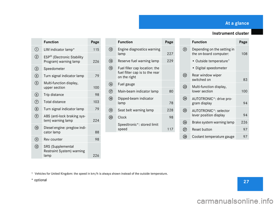
Instrument cluster
27Function Page
1
LIM indicator lamp* 115
2
ESP
®
(Electronic Stability
Program) warning lamp 226
3
Speedometer
4
Turn signal indicator lamp 79
5
Multi-function display,
upper section
100
6
Trip distance 98
7
Total distance 103
8
Turn signal indicator lamp 79
9
ABS (anti-lock braking sys-
tem) warning lamp
224
a
Diesel engine: preglow indi-
cator lamp
88
b
Rev counter 98
c
SRS (Supplemental
Restraint System) warning
lamp
226 Function Page
d
Engine diagnostics warning
lamp
227
e
Reserve fuel warning lamp 229
f
Fuel filler cap location: the
fuel filter cap is to the rear
on the right g
Fuel gauge
h
Main-beam indicator lamp 80
j
Dipped-beam indicator
lamp
78
k
Seat belt warning lamp 228
l
Clock 98
Speedtronic*: stored limit
speed
117 Function Page
m
Depending on the setting in
the on-board computer:
108
• Outside temperature
1 • Digital speedometer
n
Rear window wiper
switched on
83
o
Multi-function display,
lower section
100
p
AUTOTRONIC*: drive pro-
gram display
94
q
AUTOTRONIC*: selector
lever position display
94
r
Brake system warning lamp 226
s
Reset button 97
t
Coolant temperature gauge 97
1
Vehicles for United Kingdom: the speed in km/h is always shown instead of the outside temperature. At a glance
* optional
169_AKB; 2; 4, en-GB
wdomann,
Version: 2.10.6
2008-07-16T08:52:06+02:00 - Seite 27 Dateiname: 6515_0315_02_buchblock.pdf; preflight
Page 32 of 305
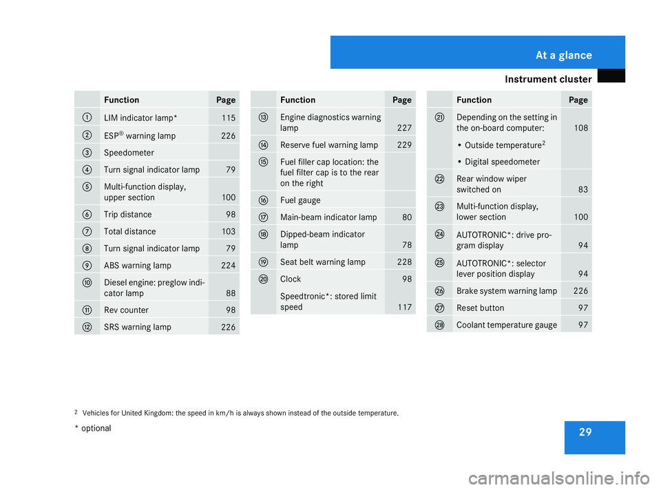
Instrument cluster
29Function Page
1
LIM indicator lamp* 115
2
ESP
®
warning lamp 226
3
Speedometer
4
Turn signal indicator lamp 79
5
Multi-function display,
upper section
100
6
Trip distance 98
7
Total distance 103
8
Turn signal indicator lamp 79
9
ABS warning lamp 224
a
Diesel engine: preglow indi-
cator lamp
88
b
Rev counter 98
c
SRS warning lamp
226 Function Page
d
Engine diagnostics warning
lamp
227
e
Reserve fuel warning lamp 229
f
Fuel filler cap location: the
fuel filter cap is to the rear
on the right g
Fuel gauge
h
Main-beam indicator lamp 80
j
Dipped-beam indicator
lamp
78
k
Seat belt warning lamp 228
l
Clock 98
Speedtronic*: stored limit
speed
117 Function Page
m
Depending on the setting in
the on-board computer:
108
• Outside temperature
2 • Digital speedometer
n
Rear window wiper
switched on
83
o
Multi-function display,
lower section
100
p
AUTOTRONIC*: drive pro-
gram display
94
q
AUTOTRONIC*: selector
lever position display
94
r
Brake system warning lamp 226
s
Reset button 97
t
Coolant temperature gauge 97
2
Vehicles for United Kingdom: the speed in km/h is always shown instead of the outside temperature. At a glance
* optional
169_AKB; 2; 4, en-GB
wdomann,
Version: 2.10.6
2008-07-16T08:52:06+02:00 - Seite 29 Dateiname: 6515_0315_02_buchblock.pdf; preflight
Page 100 of 305

Instrument cluster
97Instrument cluster
Points to remember
You will find an illustration of the instrument
cluster in the "At a glance" section
(Y page 26). G
Risk of accident
No further messages can be displayed if the
instrument cluster and/or the multi-func-
tion display fails.
This means that you will not see information
about the driving situation, such as the
speed, outside temperature, warning/indi-
cator lamps, display messages or system
failures. The vehicle's handling character-
istics may be affected. Adjust your driving
style and speed accordingly.
Immediately consult a qualified specialist
workshop which has the necessary special-
ist knowledge and tools to carry out the
work required. Mercedes-Benz recom-
mends that you use a Mercedes-Benz
Service Centre for this purpose. In particu-
lar, work relevant to safety or on safety-
related systems must be carried out at a
qualified specialist workshop. Activating the multi-function display
X Switch on the ignition. The multi-function display is also activated
when you:
R
switch on the lights
R press reset button 1
R open the driver's door Adjusting the instrument cluster
ligh
ting
X Brighter or dimmer: briefly turn reset but-
ton 1clockwise or anti-clockwise to the
stop and release.
The brightness of the instrument cluster
lighting changes by one level. There are
several possible levels. Coolant temperature gauge
The coolant temperature gauge is in the
instrument cluster on the left-hand side.
Under normal operating conditions and with
the specified coolant level, the coolant tem-
perature may rise to 120 †. The coolant tem-
perature may rise to the top end of the scale
at high outside temperatures and on long
uphill stretches. Controls
169_AKB; 2; 4, en-GB
wdomann, Version: 2.10.6 2008-07-16T08:52:06+02:00 - Seite 97 ZDateiname: 6515_0315_02_buchblock.pdf; preflight
Page 178 of 305

Engine compartment
175H
Environmental note
When topping up the oil, take care not to
spill any. Oil must not be allowed to escape
into the soil or waterways. You would oth-
erwise be damaging the environment.
For further information on engine oil
(Y page 296). Coolant
G
Risk of injury
The cooling system is pressurised. There-
fore, only unscrew the cap once the engine
has cooled down. The coolant temperature
gauge must display less than 70 °C. You
could otherwise be scalded by escaping hot
coolant.
Coolant consists of water and antifreeze/cor-
rosion inhibitor. Only check the coolant level
when the vehicle is on a level surface and the
engine has cooled down. Checking the coolant level The coolant expansion tank is located in the
engine compartment on the right when
viewed in the direction of travel.
1
Cap
2 Coolant expansion tank
3 Marker bar
X Slowly turn cap 1half a turn anti-clock-
wise to allow excess pressure to escape.
X Turn cap 1further anti-clockwise and
remove it.
There is sufficient coolant in expansion
tank 2if the coolant is level with marker
bar 3in the filler neck when cold or
approximately 1.5 cm higher when hot. X
Top up the coolant if necessary.
X Replace cap 1and tighten all the way to
the stop.
For further information on coolant see
(Y page 297) . Windscreen washer system/head-
lamp cleaning system*
The washer fluid reservoir is located in the
engine compartment on the left-hand side of
the vehicle when viewed in the direction of
travel. The headlamp cleaning system is also
supplied from the washer fluid reservoir. 1
Cap
X Add windscreen washer concentrate to the
washer fluid all year round. Operation
* optional
169_AKB; 2; 4, en-GB
wdomann
,V ersion: 2.10.6
2008-07-16T08:52:06+02:00 - Seite 175 ZDateiname: 6515_0315_02_buchblock.pdf; preflight
Page 215 of 305

Display
messages 212 Symbol messages
G
Risk of ac
cident and injury
If maintenance work is carried out incorrectly this can jeopardise the operating safety of your vehicle. You risk losing control of your vehicle
and thereby causing an accident. The safety systems may also no longer be able to protect you or others as they are designed to do.
Always have maintenance work carried out at a qualified specialist workshop which has the necessary specialist knowledge and tools to
carry out the work required.
Mercedes-Benz recommends that you use a Mercedes-Benz Service Centre for this purpose.
In particular, all work relevant to safety or on safety-related systems must be carried out at a qualified specialist workshop. Display messages Possible cause/consequence Possible solution
< G
Risk of injury
If the symbol appears in the multi-function
display, a seat belt buckle has been
released on a rear seat during the journey. X
Ask occupants in the rear to fasten their seat
belts.
Further information on the status indicator for the
rear seat belts* (Y page 76). 1 The tailgate is open. X
Close the tailgate. 2 At least one door is open. X
Close the doors. ± Some electronic systems are unable to
send information to the on-board com-
puter. The following functions may be mal-
functioning:
R
coolant temperature display
R rev counter
R cruise control *or Speedtronic* display X
Visit a qualified specialist workshop. Practical advice
* optional
169_AKB; 2; 4, en-GB
wdomann,
Version: 2.10.6
2008-07-16T08:52:06+02:00 - Seite 212 Dateiname: 6515_0315_02_buchblock.pdf; preflight
Page 216 of 305

Display
messages 213Display messages Possible cause/consequence Possible solution
D The engine fan is fa
ulty. X
If the coolant temperature is less than 120 †,
you can continue driving to the nearest quali-
fied specialist workshop.
X Avoid subjecting the engine to heavy loads, e.g.
driving in mountainous terrain, and stop-and-
go driving. # The battery is not being charged. One (or
more) of the following could be the cause:
R
a faulty alternator
R a torn poly-V-belt
R a malfunction in the electronics X
Stop immediately and safely when traffic con-
ditions permit and switch off the engine.
X Check the poly-V-belt.
X If the poly-V-belt is torn: do not continue
driving. Consult a qualified specialist work-
shop.
X If the poly-V-belt is not damaged: have the
vehicle checked immediately at a qualified spe-
cialist workshop. The on-board voltage is too high. X
Have the alternator checked at a qualified spe-
cialist workshop. 2 Brake wear The brake pads/linings have reached
their wear limit. X
Visit a qualified specialist workshop. Practical advice
169_AKB; 2; 4, en-GB
wdomann
,V ersion: 2.10.6
2008-07-16T08:52:06+02:00 - Seite 213 ZDateiname: 6515_0315_02_buchblock.pdf; preflight