MERCEDES-BENZ AMG GT ROADSTER 2018 Owners Manual
Manufacturer: MERCEDES-BENZ, Model Year: 2018, Model line: AMG GT ROADSTER, Model: MERCEDES-BENZ AMG GT ROADSTER 2018Pages: 409, PDF Size: 7.66 MB
Page 101 of 409
Exterior lighting
Note
s onchanging the lights when driving
abroad It is not necessary
tochange the headlamps.
The legal requirements are also met in countries
in which traf fic drives on theot her side of the
ro ad. Information about lighting sy
stems and your
re sponsibility The
various lighting sy stems of theve hicle are
only aids. The driver of theve hicle is responsible
fo r cor rect vehicle illumination in accordance
with the pr evailing light and visibility conditions,
legal requirements and traf fic situation. Light switch
Ope
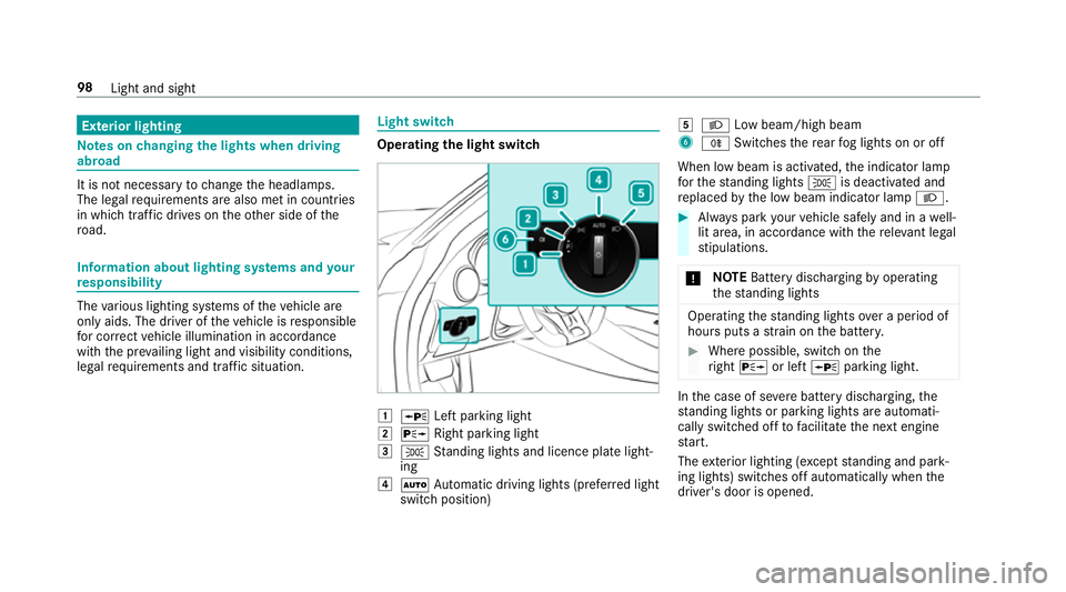
rating the light switch 1
W Left pa rking light
2 X Right parking light
3 T Standing lights and licence plate light‐
ing
4 Ã Automatic driving lights (prefer red light
switch position) 5
L Low beam/high beam
6 R Switches there ar fog lights on or off
When low beam is activated, the indicator lamp
fo rth est anding lights Tis deactivated and
re placed bythe low beam indicator lamp L. #
Alw ays park your vehicle safely and in a well-
lit area, in accordance with there leva nt le gal
st ipulations.
* NO
TEBattery discharging byoperating
th est anding lights Operating
thest anding lights over a period of
hours puts a stra in on the batter y. #
Where possible, switch on the
ri ght X or left Wparking light. In
the case of se vere battery discharging, the
st anding lights or parking lights are automati‐
cally swit ched off tofacilitate the next engine
st art.
The exterior lighting (e xcept standing and park‐
ing lights) swit ches off automatically when the
driver's door is opened. 98
Light and sight
Page 102 of 409
R
Obser vethe no tes on sur round lighting
(/ page 102).
Au tomatic driving lights function
The standing lights, low beam and daytime run‐
ning lights are switched on au tomatical ly
depending on the ignition status and the light
conditions. &
WARNING Risk of accident when the
dipped beam is switched off in poor visi‐
bility
When the light switch is set toà ,the
dipped beam may not be switched on auto‐
matically if there is fog, snow or other causes
of poor visibility such as spr ay.#
In such cases, turn the light switch to
L . The automatic driving lights are only an aid.
Yo u
are responsible forve hicle lighting. Switching
there ar fog lights on or off
Re quirements:
R The light switch is in theL orà posi‐
tion. #
Press the R button.
Please obser vethe count ry-specific la wsonthe
use of rear fog lamps. Operating
the combination switch for the
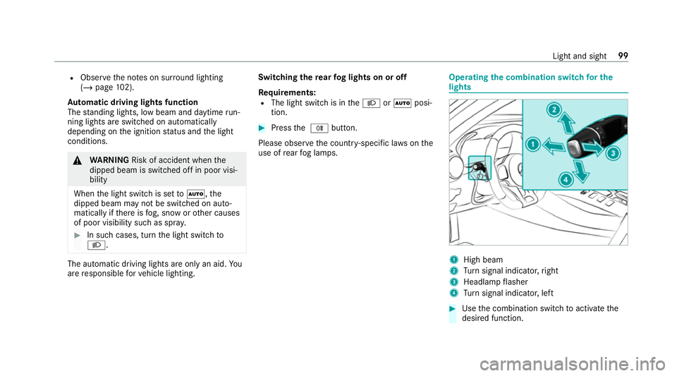
lights 1
High beam
2 Turn signal indicator, right
3 Headlamp flasher
4 Turn signal indicator, left #
Use the combination switch toactivate the
desired function. Light and sight
99
Page 103 of 409
High beam
#
Toswitch on: turnthe light switch tothe
L orà position. #
Press the combination switch be yond the
point of resis tance in the direction of ar row
1 .
When the high beam is activated, the indica‐
to r lamp for low beam Lwill be deactiva‐
te d and replaced bythe indicator lamp for
high beam K. #
Toswitch off: movethe combination switch
back toits starting position.
Headla mpflasher #
Pull the combination switch in the direction
of ar row3.
Tu rn signal indicators #
Toindicate briefl y:press the combination
switch briefly tothe point of resis tance in the
direction of ar row2or4.
The cor responding turn signal indicator will
fl ash thre e times. #
Toindicate permanentl y:press the combi‐
nation switch be yond the point of resis tance
in the direction of ar row2or4. Ac
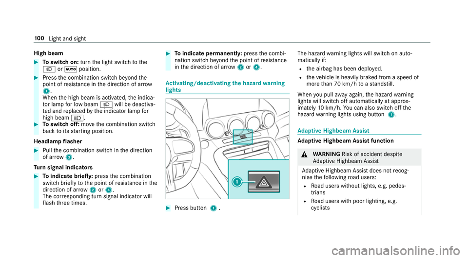
tivating/deactivating the hazard warning
lights #
Press button 1. The hazard
warning lights will switch on auto‐
matically if:
R the airbag has been deplo yed.
R theve hicle is heavily braked from a speed of
more than 70 km/h toast andstill.
When you pull away again, the hazard warning
lights will switch off automatically at appr ox‐
imately 10km/h. You can also swit choff the
hazard warning lights using button 1. Ad
aptive Highbeam Assist Ad
aptive Highbeam Assist function &
WARNING Risk of accident despi te
Ad aptive Highbeam Assist
Ad aptive Highbeam Assist does not recog‐
nise thefo llowing road users:
R Road users without lights, e.g. pedes‐
trians
R Road users with poor lighting, e.g.
cyclists 100
Light and sight
Page 104 of 409
R
Road users whose lighting is obstructed,
e.g. bya bar rier
On very rare occasions, Adaptive Highbeam
Assist may failto recognise other road users
with their own lighting, or may recognise
th em too late.
In this, or in similar situations, the automatic
main beam will not be deactivated or will be
activated despite the presence of other road
users. #
Alw ays obser vethe tra ffic carefully and
switch off the main beam in good time. Ad
aptive Highbeam Assist cannot take into
account road, weather or traf fic conditions.
De tection may be restricted in thefo llowing
cases:
R In poor visibilit y,e.g. fog, heavy rain or snow
R Ifth ere is dirt on the sensors or the sensors
are obscured
Ad aptive Highbeam Assist is on lyan aid. You are
re sponsible for adju sting theve hicle's lighting toth
e pr evailing light, visibility and traf fic condi‐
tions. The
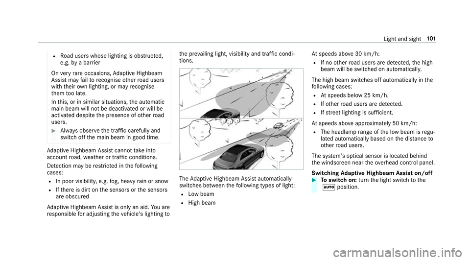
Adaptive Highbeam Assist automatically
swit ches between thefo llowing types of light:
R Low beam
R High beam At
speeds abo ve30 km/h:
R If no other road users are de tected, the high
beam will be switched on automaticall y.
The high beam switches off automatically in the
fo llowing cases:
R Atspeeds below 25 km/h.
R Ifot her road users are de tected.
R Ifstre et lighting is suf ficient.
At speeds abo veappr oximately 50 km/h:
R The headlamp range of the low beam is regu‐
lated automatically based on the dis tance to
ot her road users.
The sy stem's optical sensor is located behind
th e windscreen near theov erhead control panel.
Switching Adaptive Highbeam Assist on/off #
Toswitch on: turnthe light switch tothe
à position. Light and sight
101
Page 105 of 409
#
Switch on the main beam using the combina‐
tion switch.
When the main beam is switched on auto‐
matically in the dar k,the _ indicator
lamp on the multifunction display comes on. #
Toswitch off: switch offthe main beam
using the combination switch. Setting
theex terior lighting switch-off delay
time Multimedia sy
stem:
4 Vehicle 5
÷ Light settings
5 Exterior light shut-off #
Set the switch-off delay time. Setting
the sur round lighting Multimedia sy
stem:
4 Vehicle 5
÷ Light settings
5 Locator lighting #
Activate Oor deacti vate ª the function. If
th e sur round lighting is swit ched on, theex te‐
ri or lighting remains lit for 40 seconds af terthe
ve hicle is unloc ked. When youstart theve hicle,
th e sur round lighting is deactivated and the
automatic driving lights are activated. Interior lighting
Ad
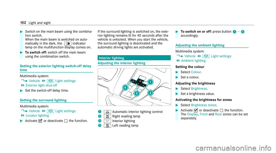
justing the in terior lighting 1
| Automatic interior lighting control
2 p Rightreading lamp
3 c Inte rior lighting
4 p Leftreading lamp #
Toswitch on or off: press button1–4
accordingly. Ad
justing the ambient lighting Multimedia sy
stem:
4 Vehicle 5
÷ Light settings
5 Ambient lighting
Setting the colour #
Select Colour. #
Set a colour.
Ad justing the brightness #
Select Brightness . #
Set a brightness value.
Ac tivating the brightness for zones #
Select Brightness zones . #
Activate Oor deacti vate ª the function.
The Display ,Front andRear zones can be set
separately. 102
Light and sight
Page 106 of 409
Setting
the interior lighting switch-off delay
time Multimedia sy
stem:
4 Vehicle 5
÷ Light settings
5 Interior light shut-off #
Set the switch-off delay time. Wi
ndscreen wipers and windscreen washer
sy stem Switching
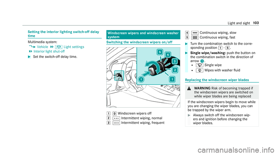
the windscreen wipers on/off 1
gWindsc reen wipers off
2 Ä Intermittent wiping, normal
3 Å Intermittent wiping, frequent 4
° Continuous wiping, slow
5 ¯ Continuous wiping, fast #
Turn the combination switch tothe cor re‐
sponding position 1-5. #
Single wipe/washing: pushthe button on
th e combination switch in the direction of
ar row 1.
R í Single wipe
R î Wipes with washer fluid Re
placing the windsc reen wiper blades &
WARNING Risk of becoming trapped if
th e windscreen wipers are switched on
while wiper blades are being replaced
If th e windscreen wipers begin tomo vewhile
yo u are changing the wiper blades, you can
be trapped bythe wiper arm. #
Alw ays switch off the windscreen wip‐
ers and ignition before changing the
wiper blades. Light and sight
103
Page 107 of 409
Moving
the wiper arms tothech ange posi‐
tion #
Switch the ignition on and switch off again
immediatel y. #
Within around 15seconds, press theî
button on the combination switch for appro x‐
ima tely thre e seconds (/ page103).
The wiper arms will mo veinto thech ange
position.
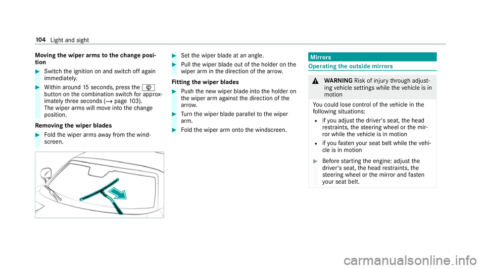
Re moving the wiper blades #
Foldthe wiper arms away from the wind‐
screen. #
Set the wiper blade at an angle. #
Pull the wiper blade out of the holder on the
wiper arm in the direction of the ar row.
Fi tting the wiper blades #
Push the new wiper blade into the holder on
th e wiper arm against the direction of the
ar row. #
Turn the wiper blade parallel tothe wiper
arm. #
Foldthe wiper arm onto the windscreen. Mir
rors Operating
the outside mir rors &
WARNING Risk of inju rythro ugh adjust‐
ing vehicle settings while theve hicle is in
motion
Yo u could lose cont rol of theve hicle in the
fo llowing situations:
R ifyo u adjust the driver's seat, the head
re stra ints, thesteering wheel or the mir‐
ro r while theve hicle is in motion
R ifyo ufast enyour seat belt while theve hi‐
cle is in motion #
Before starting the engine: adjust the
driver's seat, the head restra ints, the
st eering wheel or the mir ror and fasten
yo ur seat belt. 104
Light and sight
Page 108 of 409
&
WARNING Risk of accident due tomis‐
judgement of dis tances when using the
outside mir ror
The outside mir rors reflect objects on a
smaller scale. The objects in view are in fact
closer than they appear.
As a result, you may misjud gethe dis tance
between you and thero ad user driving
behind you, e.g. when changing lanes. #
Therefore, alw ays look over your shoul‐
der in order toensure that you are
aw are of the actual dis tance between
yo u and thero ad users driving behind
yo u. Fo
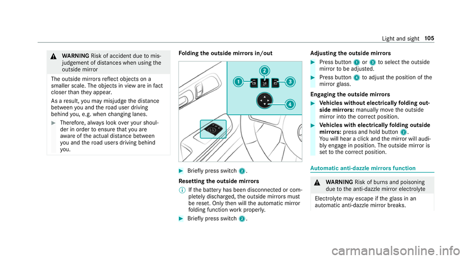
lding the outside mir rors in/out #
Brief lypress switch 2.
Re setting the outside mir rors
% Ifth e battery has been disconnected or com‐
ple tely discharged, the outside mir rors must
be reset. Only then will the automatic mir ror
fo lding function workproperly. #
Brief lypress switch 2. Ad
justing the outside mir rors #
Press button 1or3 toselect the outside
mir rorto be adjus ted. #
Press button 4toadjust the position of the
mir rorgl ass.
Engaging the outside mir rors #
Vehicles without electrical lyfolding out‐
side mir rors:manually mo vethe outside
mir ror into the cor rect position. #
Vehicles with electrical lyfolding outside
mir rors: press and hold button 2.
Yo u will hear a click and the mir ror will audi‐
bly engage in position. The outside mir ror is
set tothe cor rect position. Au
tomatic anti-dazzle mir rors function &
WARNING Risk of bu rns and poisoning
due tothe anti-dazzle mir ror electrolyte
Electrolyte may escape if theglass in an
automatic anti-dazzle mir ror breaks. Light and sight
105
Page 109 of 409
The electrolyte is harmful and causes ir
rita‐
tion. It mu stnot come into contact wi thyour
skin, eyes,respiratory organs or clo thing or
be swallo wed. #
Ifyo u come into contact with electro‐
ly te , obser vethefo llowing:
R Rinse the electrolyte from your skin
and seek medical attention immedi‐
atel y.
R If electrolyte comes into contact
with your eyes, rinse them thor‐
oughly with clean water and seek
medical attention immediately.
R Ifth e electrolyte is swallo wed,
immediately rinse your mouth out
th oroughly. Do not induce vomiting.
Seek medical attention immediately.
R Immedia tely ch ange out of clo thing
which has come into con tact wi th
electrolyte.
R If an allergic reaction occurs, seek
medical attention immediatel y. The inside
rearview mir ror and the outside mir‐
ro r on the driver's side automatically go into
anti-dazzle mode if light from a headlamp hits
th e sensor on the inside rearview mir ror.
Sy stem limitations
The sy stem does not go into anti-dazzle mode in
th efo llowing situations:
R the engine is switched off
R reve rsege ar is engaged
R the interior lighting is switched on Fu
nction of the front-passenger outside mir‐
ro r parking position The pa
rking position makes parking easier.
The front-passenger outside mir ror tilts down‐
wa rds and sho ws there ar wheel on the front-
passenger side in thefo llowing situations:
R the parking position is stored (/ page107)
R the front-passen ger mir ror is selected
R reve rsege ar is engaged The front-passenger outside mir
ror mo ves back
to its original position in thefo llowing situations:
R you shift the transmission toano ther trans‐
mission position
R you are tra velling at speeds greaterth an
15 km/h
R you press the button forth e outside mir ror
on the driver's side 106
Light and sight
Page 110 of 409
St
oring the pa rking position of the front-
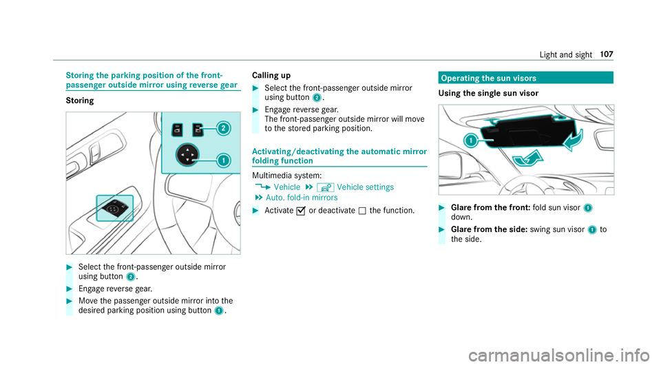
passenger outside mir ror using reve rsege ar St
oring #
Select the front-passen ger outside mir ror
using but ton2. #
Engage reve rsege ar. #
Movethe passenger outside mir ror into the
desired parking position using button 1.Calling up #
Select the front-passen ger outside mir ror
using but ton2. #
Engage reve rsege ar.
The front-passenger outside mir ror will mo ve
to thestored parking position. Ac
tivating/deactivating the automatic mir ror
fo lding function Multimedia sy
stem:
4 Vehicle 5
î Vehicle settings
5 Auto. fold-in mirrors #
Activate Oor deacti vate ª the function. Operating
the sun visors
Using the single sun visor #
Glarefrom the front: fold sun visor 1
down. #
Glare from the side: swing sun visor 1to
th e side. Light and sight
107