boot MERCEDES-BENZ AMG GT ROADSTER 2018 Owner's Manual
[x] Cancel search | Manufacturer: MERCEDES-BENZ, Model Year: 2018, Model line: AMG GT ROADSTER, Model: MERCEDES-BENZ AMG GT ROADSTER 2018Pages: 409, PDF Size: 7.66 MB
Page 258 of 409
*
NO
TEDama gedue tounsuitable car
wa sh #
Before driving into a car wash make
sure that the car wash is suitable for
th eve hicle dimensions. #
Ensure there is suf ficient ground clear‐
ance between the underbody and the
guide rails of the car wash. #
Ensure that the clearance width of the
car wash, in particular the width of the
guide rails, is suf ficient. To
avo id damage to yourvehicle when using a
car wash, ensure thefo llowing beforehand:
R toavoid possible water ingress in theve hicle,
it is preferable touse car washes which allow
th e high-pressure pre-cleaning tobe deacti‐
va ted (specification forth e cabriolet pro‐
gram).
R it is imperative toavo id a subsequent hot-
wa x treatment.
R remo vetheke y in order toensure that the
wind deflector on the windscreen retracts. R
Active Dis tance Assi stDISTRONIC and the
HOLD function are deactivated.
R theex tendable rear wing is comple tely
re tracted.
R the side windo wsand soft top are closed
comple tely.
R the blo werfo rth eve ntilation/heating is
switched off.
R the windscreen wiper switch is in position
g.
R theke y is at a minimum dis tance of 3 m
aw ay from theve hicle, otherwise the boot lid
could open unintentionall y.
R in car washes with a con veyo r sy stem: neu‐
tral iis engaged.
% In car washes with a con veyo r sy stem: if you
wo uld like tolea vetheve hicle while it is
being washed, make sure theke y is located
in theve hicle. The jgear is otherwise
automatically engaged.
% If, af terth e car wash, youre mo vethewax
from the windscreen and wiper rubbers, this will pr
event smearing and reduce wiper
noise. Information on using a high-p
ressure cleaner &
WARNING Risk of an accident when
using high-pressure cleane rswith circu‐
lar jet nozzles
The wate r jet of a circular jet nozzle (dirt
grinder) can cause extern ally invisible dam‐
age tothe tyres or chassis parts.
Components damaged in this wa y may unex‐
pec tedly fail. #
Do not use high-pressure cleaners with
circular jet nozzles toclean theve hicle. #
Have damaged tyres or chassis parts
re placed immediatel y. To
avo id damage to yourvehicle, obser vethefo l‐
lowing when using a high-pressure cleaner:
R keep theke y at least 3 m away from theve hi‐
cle. Otherwise the boot lid could open unin‐
te ntional ly. Maintenance and care
255
Page 269 of 409
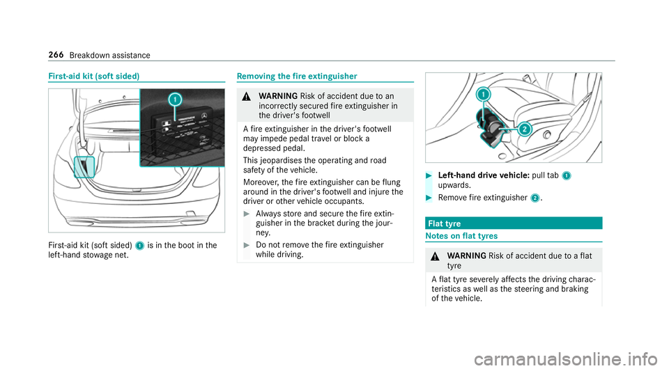
Fi
rs t-aid kit (soft sided) Fir
st-aid kit (so ftsided) 1is in the boot in the
left-hand stowage net. Re
moving the fire extinguisher &
WARNING Risk of accident due toan
incor rectly secu redfire extinguisher in
th e driver's foot we ll
A fire extinguisher in the driver's foot we ll
may impede pedal tra vel or block a
depressed pedal.
This jeopardises the operating and road
saf ety of theve hicle.
Moreo ver,th efire extinguisher can be flung
around in the driver's foot we ll and injure the
driver or other vehicle occupants. #
Alw aysst ore and secure thefire extin‐
guisher in the brac ket du ring the jour‐
ne y. #
Do not remo vethefire extinguisher
while driving. #
Left-hand drive vehicle: pulltab1
upwards. #
Remo vefire extinguisher 2. Flat tyre
Note
s onflat tyres &
WARNING Risk of accident due toaflat
tyre
A flat tyre se verely affects the driving charac‐
te rist ics as well as thesteering and braking
of theve hicle. 266
Breakdown assis tance
Page 271 of 409
Ve
hicles with tyre pressure monitoring sys‐
te m: MOExtended tyres may only be used in
conjunction wi than activated tyre pressure mon‐
itoring sy stem.
If a pressure loss warning message appears in
th e multifunction displa y,proceed as follo ws:
R Check the tyre for dama ge.
R If driving on, obser vethefo llowing no tes.
Driving distance possible in emer gency
mode af ter the pressure loss warning: Load condition Driving distance pos‐
sible in emergency
mode
Pa rtially laden 80 km
Fu lly laden 30 kmThe driving dis
tance possible in emergency
mode may vary depending on the driving style.
Obser vethe maximum permissible speed of
80 km/h. If a tyre has gone
flat and cannot be replaced
with an MOEx tended tyre, you can use a stand‐
ard tyre as a temp orary measure. TIREFIT kit
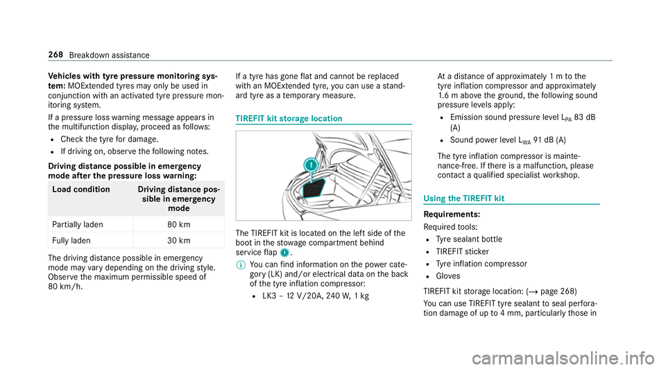
storage location The TIREFIT kit is located on
the left side of the
boot in thestow age compartment behind
service flap 1.
% You can find information on the po wer cate‐
gory (LK) and/or electrical data on the back
of the tyre inflation compressor:
R LK3 – 12V/20A, 240W, 1kg At
a dis tance of appr oximately 1 m tothe
tyre inflation compressor and appr oximately
1. 6 m abo vethe ground, thefo llowing sound
pressure le vels apply:
R Emission sound pressure le vel L
PA 83 dB
(A)
R Sound po wer le vel L
WA 91
dB (A)
The tyre inflation compressor is mainte‐
nance-free. If there is a malfunction, please
conta ct aqualified specialist workshop. Using
the TIREFIT kit Re
quirements:
Re quired tools:
R Tyre sealant bottle
R TIREFIT sticker
R Tyre inflation compressor
R Gloves
TIREFIT kit storage location: (/ page 268)
Yo u can use TIREFIT tyre sealant toseal per fora‐
tion dama geof up to4 mm, particularly those in 268
Breakdown assis tance
Page 284 of 409
As a
result, when transporting vehicles with
th eAd aptive Damping Sy stem PLUS, the
ve hicle/trailer combination may start toskid.
Consequentl y,yo u could lose cont rol of your
ve hicle. #
When transporting, ensure that:
R theve hicle has been loaded onto
th e transpor ter cor rectly
R theve hicle is secured at all four
wheels with suitable tensioning
st ra ps
R the maximum permissible speed of
60 km/h is not exceeded when
transporting *
NO
TEDama getotheve hicle from secur‐
ing it incor rectly #
After loading, theve hicle must be
secured on all four wheels. Otherwise,
th eve hicle could be damaged. #
A minimum dis tance of 20 cm up wards
and 10cm down wards must be kept to
th e transport platform. #
Secure theve hicle on all four wheels af ter
loading. #
Make sure that the front and rear axles come
to rest on the same transpor tation vehicle.
* NO
TEDama getothe driv etra in due to
incor rect positioning #
Do not position theve hicle abo vethe
connection point of the transport vehi‐
cle. To
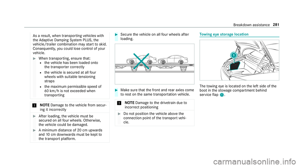
wing eyesto rage location The
towing eye is located on the left side of the
boot in thestow age compartment behind
service flap 1. Breakdown assis
tance 281
Page 286 of 409
Blown fuses must be
replaced with fuses of the
same rating, which you can recognise bythe col‐
our and fuse rating. The fuse ratings and fu rther
information tobe obser ved are lis ted in the fuse
assignment diagram.
Fu se assignment diag ram: onthe fuse box in
th e boot (/ page 284).
* NO
TEDama geor malfunctions caused
by moisture Moisture may cause dama
getothe electrical
sy stem or cause it tomalfunction. #
When the fuse box is open, make sure
th at no moisture can enter the fuse
box. #
When closing the fuse box, make sure
th at the seal of the lid is positioned cor‐
re ctly on the fuse box. If
th e newly inser ted fuse also blo ws, ha vethe
cause traced and rectified at a qualified special‐
ist workshop, e.g. a Mercedes-Benz Service
Centre. Ensure
thefo llowing before replacing a fuse:
R The vehicle is secured against rolling away.
R All electrical consumers are switched off.
R The ignition is switched off.
The electrical fuses are located in various fuse
bo xes:
R Fuse box in the front passenger foot we ll
(/ page 283)
R Fuse box in the boot on the left-hand side of
th eve hicle, when vie wed in the direction of
tr av el (/ page 284) Opening and closing
the fuse box in the front
passenger foot we ll Obser
vethe no tes on electrical fuses
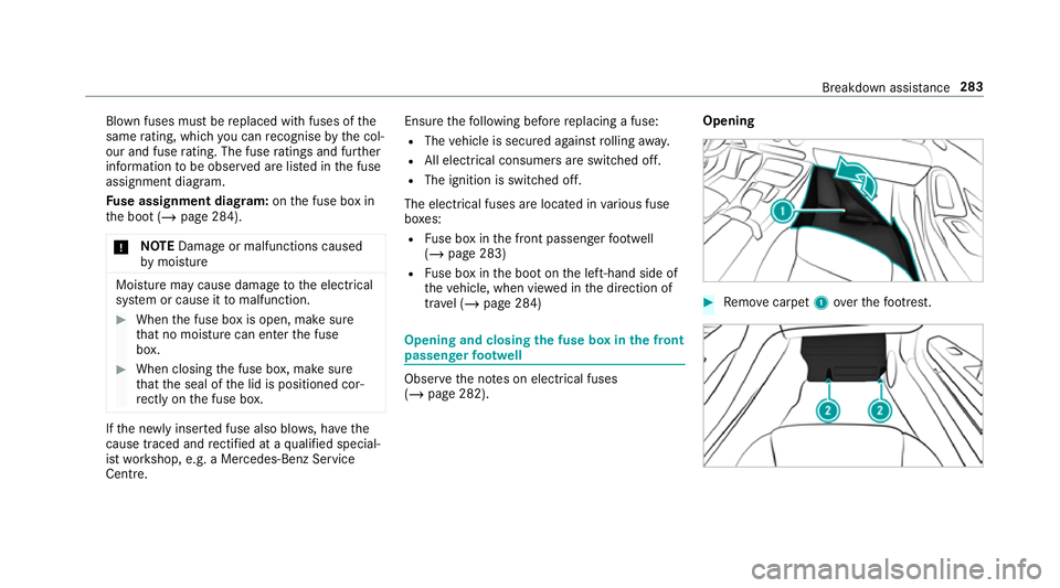
(/ page 282). Opening #
Remo vecarpet 1over thefo ot re st. Breakdown assis
tance 283
Page 287 of 409
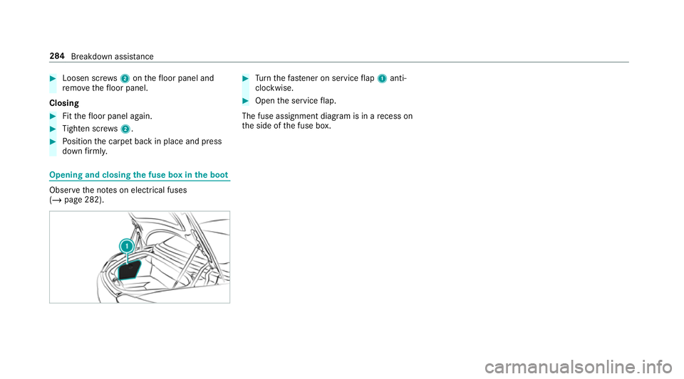
#
Loosen scr ews2 onthefloor panel and
re mo vethefloor panel.
Closing #
Fitthefloor panel again. #
Tighten scr ews2. #
Position the carpet back in place and press
down firm ly. Opening and closing
the fuse box in the boot Obser
vethe no tes on electrical fuses
(/ page 282). #
Turn thefast ener on service flap 1 anti-
clo ckwise. #
Open the service flap.
The fuse assignment diagram is in a recess on
th e side of the fuse box. 284
Breakdown assis tance
Page 302 of 409
R
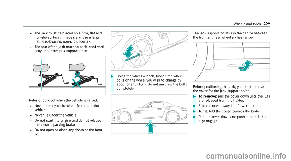
The jack must be placed on a firm ,fl at and
non-slip sur face. If necessar y,use a lar ge,
fl at, load-bearing, non-slip unde rlay.
R The foot ofthe jack must be positioned verti‐
cally under the jack support point. Ru
les of conduct when theve hicle is raised:
R Never place your hands or feet under the
ve hicle.
R Never lie under theve hicle.
R Do not start the engine and do not release
th e electric parking brake.
R Do not open or close any doors or the boot
lid. #
Using the wheel wrench, loosen the wheel
bolts on the wheel you wish tochange by
about one full turn. Do not unscr ewthe bolts
comple tely. The jack support point is in
the cent rebetween
th e front and rear wheel ar ches (ar row). Before positioning
the jac k,you must remo ve
th e co verfo rth e jack support point. #
Toremo ve:pull the co ver down until the lugs
are released from the holder. #
Foldthe co veraw ay in a forw ard direction. #
Tofit: fold the co verto wa rdsth e body. #
Pull the co ver down and push it in until the
lugs engage. Wheels and tyres
299
Page 306 of 409
Collapsible spa
rewheel Note
s onthe collapsible spa rewheel &
WARNING Risk of accident caused by
incor rect wheel and tyre dimensions
The wheel or tyre size and the tyre type of
th e emer gency spa rewheel or spare wheel
and the wheel tobe replaced may dif fer.
Mounting an emer gency spa rewheel/spare
wheel may se verely impair the driving char‐
acteristics.
To preve nt hazardous situations: #
Adapt your driving style according lyand
drive carefull y. #
Neverfit more than one emer gency
spa rewheel or spare wheel that dif fers
in size. #
Only use an emer gency spa rewheel or
spare wheel of a dif fere nt size brie fly. #
Do not switch off ESP ®
. #
Have the emer gency spa rewheel or
spare wheel of a dif fere nt size replaced
at the nearest qualified specialist work‐ shop. The new wheel must ha
vethe
cor rect dimensions. The collapsible spa
rewheel is only available in
cer tain countries.
The collapsible spare wheel is an emer gency
wheel which is only suitable for use for a limi ted
period of time and in a restricted manner in the
eve nt of a flat tyre (e.g. until the nearest work‐
shop).
The tyre side walls are folded when in transpo rt
mode. Before use, the collapsible spare wheel
has tobe inflated with the accompanying com‐
pressor.
Check the tyre pressure of the collapsible spare
wheel once fitted. Co rrect the pressure as nec‐
essar y.
The maximum permissible speed with a collapsi‐
ble spare wheel fitted is 80 km/h.
Do not fit snow chains with the collapsible spare
wheel.
Re place the collapsible spare wheel af ter six
ye ars at the latest, rega rdless of wear. %
Ve
hicles with a tyre pressure monitoring
sy stem: if a collapsible spare wheel is fitted
th e tyre pressure monitoring sy stem cann ot
function reliably. Only restart the sy stem
again when the collapsible spare wheel has
been replaced with a new wheel.
Ve hicles with a tyre pressure monitoring
sy stem: for a few minutes af ter a collapsible
spare wheel is fitted, the sy stem may still
display the tyre pressure of there mo ved
wheel.
Be sure toalso obse rveth efo llowing fur ther
re lated subjects:
R Notes on tyre pressure (/ page 286)
R Tyre pressure table (/ page 287) Re
moving the collapsible spare wheel The collapsible spare wheel is secured in
the col‐
lapsible spare wheel bag in the boot. #
Obser vethe information on mounting tyres
(/ page 293). #
Open the boot. Wheels and tyres
303
Page 307 of 409
#
Detach thefast ening stra ps. #
Unhook there taining spring hooks of thefa s‐
te ning stra ps from the brac kets. #
Remo vethe collapsible spare wheel bag
to ge ther with the collapsible spare wheel. #
Open the collapsible spare wheel bag and
re mo vethe collapsible spare wheel. Inflating
the collapsible spa rewheel Re
quirements:
R Mount the collapsible spare wheel as descri‐
bed. (/ page 301)
R Remo vethe tyre inflation compressor from
th estow agewell under the boot floor.
(/ page 268)
* NO
TEDama getothe collapsible spare
wheel when lo wering theve hicle Lo
we ring theve hicle without pr eviously
inflating the collapsible spare wheel can
damage its rim. #
Inflate the collapsible spare wheel using
th e tyre inflation compressor before
lo we ring theve hicle. *
NO
TEOverheating due tothe tyre infla‐
tion compressor running too long #
Do not runth e tyre inflation compres‐
sor for longer than ten minu tes without
inter ruption. #
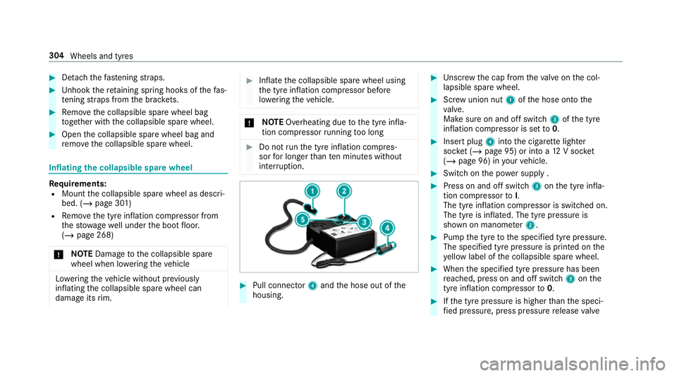
Pull connec tor4 and the hose out of the
housing. #
Unscr ew the cap from theva lve on the col‐
lapsible spare wheel. #
Screw union nut 1ofthe hose onto the
va lve.
Make sure on and off switch 3ofthe tyre
inflation compressor is set to0. #
Insert plug 4into the cigar ette lighter
soc ket (/ page 95) or into a 12V soc ket
( / page 96) in your vehicle. #
Switch on the po wer supp ly . #
Press on and off switch 3onthe tyre infla‐
tion compressor toI.
The tyre inflation compressor is switched on.
The tyre is inflated. The tyre pressure is
shown on manome ter2. #
Pump the tyre tothe specified tyre pressure.
The specified tyre pressure is printed on the
ye llow label of the collapsible spare wheel. #
When the specified tyre pressure has been
re ached, press on and off swit ch3 onthe
tyre inflation compressor to0. #
Ifth e tyre pressure is higher than the speci‐
fi ed pressure, press pressure release valve 304
Wheels and tyres
Page 354 of 409
Display messages
Possible causes/consequences and M
MSolutions #
Never unlock the engine bonn etwhen driving. #
Before every trip, ensure that the engine bonn etis loc ked. #
Stop theve hicle immediately, paying attention toroad and traf fic conditions. #
Close the bonn et.
C *A
t least one door is open. #
Close all doors.
N *T
he boot lid is open. &
DANG ER Risk of exhaust gas poisoning
Combustion engines emit poisonous exhaust gases such as carbon monoxide. Exhaust gases can enter the
ve hicle interior if the boot lid is open when the engine is running, especially if theve hicle is in motion. #
Alw ays switch off the engine before opening the boot lid. #
Never drive with the boot lid open. #
Close the boot lid. Display messages and
warning/indicator lamps 351