load capacity MERCEDES-BENZ AMG GT ROADSTER 2019 Owner's Manual
[x] Cancel search | Manufacturer: MERCEDES-BENZ, Model Year: 2019, Model line: AMG GT ROADSTER, Model: MERCEDES-BENZ AMG GT ROADSTER 2019Pages: 298, PDF Size: 7.9 MB
Page 22 of 298
PSI (pounds per square inch) (def-
inition) ...........................................2 80
Replacing ....................................... 281
Service life ..................................... 264
Sidewall (definition) ....................... 280
Speed rating (definition) ................ 280
Storing .......................................... .282
Structure and characteristics
(definition) ..................................... 279
Summer tires in winter .................. 265
Temperature .................................. 275
TIN (Tire Identification Number)
(definition) ..................................... 281
Tire bead (definition) ..................... .280
Tire pressure (definition) ................ 280
Tire pressures (recommended) ...... 279
Tire size (data) ............................... 285
Tire size designation, load-bearing capacity, speed rating .................... 276
Tire tread ....................................... 264
Tire tread (definition) ..................... 280
Total load limit (definition) ............. 281
Traction ......................................... 275
Traction (definition) ....................... 281
Tread wea r..................................... 275
Uniform Tire Quality Grading
Standards ...................................... 274
Uniform Tire Quality Grading
Standards (definition) .................... 279
Wear indicator (definition) ............. 281
Wheel and tire combination ........... 285
Wheel rim (definition) .................... 279
see Flat tire
Tool
see Vehicle tool kit
Touchpad
Changing the station/music
track .............................................. 212
Character suggestions ................... 211
Deleting characters ....................... 211
Entering a space ............................ 211
Entering characters ....................... 211
Gesture control .............................. 211
Handwriting recognition ................ 211
Operating the touchpad ................. 211
Overview ........................................ 211
Quick access for Audio .................. 212
Switching ....................................... 211 Switching input line ....................... 211
Tow-starting
Emergency engine starting ............ 261
Towing
Permitted towing methods ............ 259
Towing away
Important safety guidelines ........... 258
Installing the towing eye ................ 259
Removing the towing eye ............... 260
Transporting the vehicle ................ 260
With both axles on the ground ....... 260
Towing eye ......................................... 249
Traction system
see ETS (Electronic Traction System)
Traffic reports
see also Digital Operator's Man-
ual .................................................. 209
Transmission
Driving tips .................................... 120
Selector lever ................................ 117
see Automatic transmission
Transmission position display ......... 119
Transmission positions
General notes ................................ 117
Overview ........................................ 118
Transporting the vehicle .................. 260
Trim pieces (cleaning instruc-
tions) .................................................. 247
Trip computer (on-board com-
puter) .................................................. 162
Trip odometer
Calling up ....................................... 161
Resetting (on-board computer) ...... 162
Trunk lid
Display message ............................ 196
Important safety notes .................... 74
Locking separately ........................... 76
Opening (automatically from
inside) .............................................. 75
Opening dimensions ...................... 293
Opening/closing (from the out-
side) ................................................. 74
Unlocking with KEYLESS-GO ............ 74
Trunk load (maximum) ...................... 293
Turn signals
Display message ............................ 186
Switching on/of f.............................. 97 20
Index
Page 275 of 298
exceed XXX kg or XXX lbs." on your vehicle’s
Tire and Loading Information placard.
X Step 2: Determine the combined weight of
the driver and passengers that will be riding in your vehicle.
X Step 3: Subtract the combined weight of the
driver and passengers from XXX kilograms or
XXX lbs.
X Step 4: The resulting figure equals the avail-
able amount of cargo and luggage load capa- city. For example, if the "XXX" amount equals
1400 lbs and there will be five 150-lb pas-
sengers in your vehicle, the amount of avail-
able cargo and luggage load capacity is
650 lbs (1400 - 750 (5 x 150) = 650 lbs).
X Step 5: Determine the combined weight of
luggage and cargo being loaded on the vehi-
cle. That weight may not safely exceed the
available cargo and luggage load capacity cal- culated in step 4. Example: steps 1 to 3
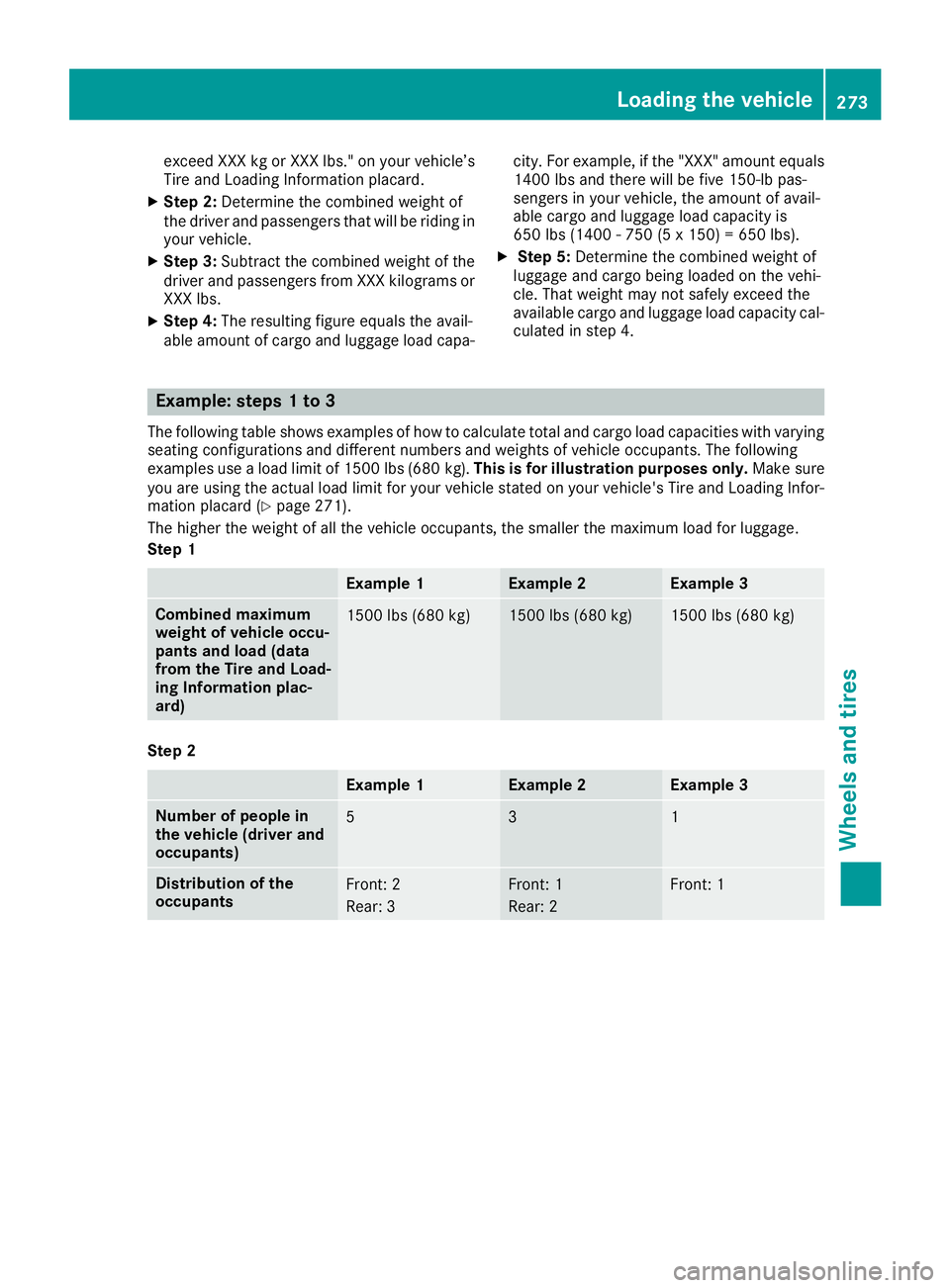
The following table shows examples of how to calculate total and cargo load capacities with varying
seating configurations and different numbers and weights of vehicle occupants. The following
examples use a load limit of 1500 lbs (680 kg). This is for illustration purposes only.Make sure
you are using the actual load limit for your vehicle stated on your vehicle's Tire and Loading Infor-
mation placard (Y page 271).
The higher the weight of all the vehicle occupants, the smaller the maximum load for luggage.
Step 1 Example 1 Example 2 Example 3
Combined maximum
weight of vehicle occu-
pants and load (data
from the Tire and Load-
ing Information plac-
ard)
1500 lbs (680 kg) 1500 lbs (680 kg) 1500 lbs (680 kg)
Step 2
Example 1 Example 2 Example 3
Number of people in
the vehicle (driver and
occupants)
5 3 1
Distribution of the
occupants
Front: 2
Rear: 3 Front: 1
Rear: 2 Front: 1Loading the vehicle
273Wheels and tires Z
Page 278 of 298
Tire labeling
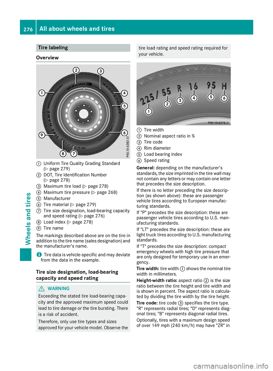
Overview 0043
Uniform Tire Quality Grading Standard
(Y page 279)
0044 DOT, Tire Identification Number
(Ypage 278)
0087 Maximum tire load (Y page 278)
0085 Maximum tire pressure (Y page 268)
0083 Manufacturer
0084 Tire material (Y page 279)
006B Tire size designation, load-bearing capacity
and speed rating (Y page 276)
006C Load index (Y page 278)
006D Tire name
The markings described above are on the tire in
addition to the tire name (sales designation) and the manufacturer's name.
i Tire data is vehicle-specific and may deviate
from the data in the example.
Tire size designation, load-bearing
capacity and speed rating G
WARNING
Exceeding the stated tire load-bearing capa-
city and the approved maximum speed could
lead to tire damage or the tire bursting. There is a risk of accident.
Therefore, only use tire types and sizes
approved for your vehicle model. Observe the tire load rating and speed rating required for
your vehicle. 0043
Tire width
0044 Nominal aspect ratio in %
0087 Tire code
0085 Rim diameter
0083 Load bearing index
0084 Speed rating
General: depending on the manufacturer's
standards, the size imprinted in the tire wall may not contain any letters or may contain one letterthat precedes the size description.
If there is no letter preceding the size descrip-
tion (as shown above): these are passenger
vehicle tires according to European manufac-
turing standards.
If "P" precedes the size description: these are
passenger vehicle tires according to U.S. man-
ufacturing standards.
If "LT" precedes the size description: these are
light truck tires according to U.S. manufacturing standards.
If "T" precedes the size description: compact
emergency wheels with high tire pressure that
are only designed for temporary use in an emer-
gency.
Tire width: tire width0043shows the nominal tire
width in millimeters.
Height-width ratio: aspect ratio0044is the size
ratio between the tire height and tire width and is shown in percent. The aspect ratio is calcula-ted by dividing the tire width by the tire height.
Tire code: tire code0087specifies the tire type.
"R" represents radial tires; "D" represents diag-
onal tires; "B" represents diagonal radial tires.
Optionally, tires with a maximum design speed
of over 149 mph (240 km/h) may have "ZR" in 276
All about
wheels and tiresWheels and tires
Page 279 of 298
the size description, depending on the manu-
facturer (e.g. 245/40 ZR 18).
Rim diameter: rim diameter0085is the diameter
of the bead seat, not the diameter of the rim
flange. The rim diameter is specified in
inches (in).
Load-bearing index: load-bearing index0083is a
numerical code that specifies the maximum
load-bearing capacity of a tire.
Do not overload the tires by exceeding the
specified load limit. The maximum permissible
load can be found on the vehicle's Tire and
Loading Information placard on the B-pillar on
the driver's side (Y page 271).
Example:
Load-bearing index 91 indicates a maximum
load of 1,356 lb (615 kg) that the tires can bear.
For further information on the maximum tire
load in kilograms and lbs, see (Y page 278).
For further information on the load bearing
index, see "Load index" (Y page 278).
Speed rating: speed rating0084specifies the
approved maximum speed of the tire.
i Tire data is vehicle-specific and may deviate
from the data in the example.
Regardless of the speed rating, always observe
the speed limits. Drive carefully and adapt your
driving style to the traffic conditions.
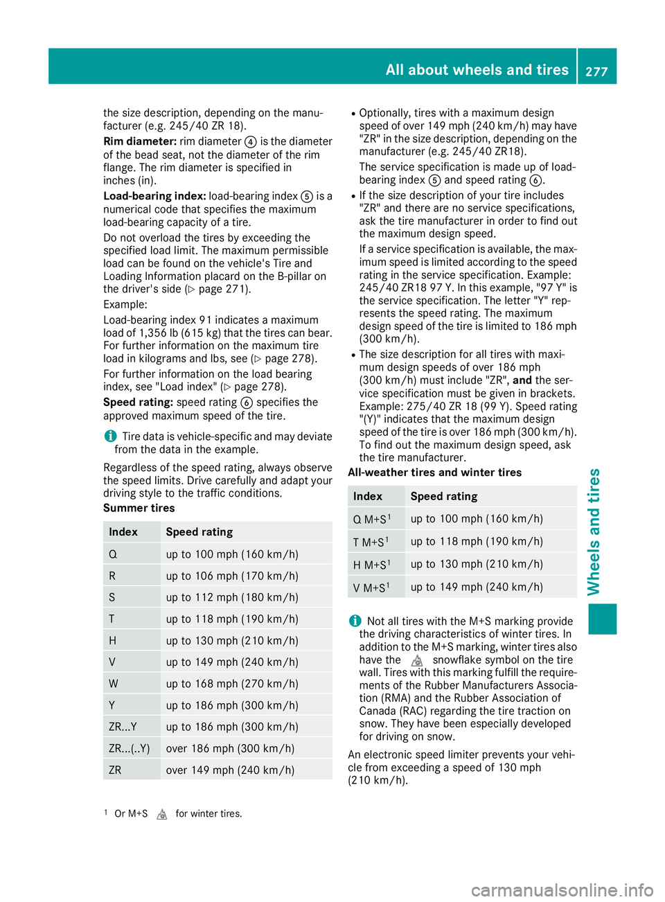
Summer tires Index Speed rating
Q up to 100 mph (160 km/h)
R up to 106 mph (170 km/h)
S up to 112 mph (180 km/h)
T up to 118 mph (190 km/h)
H up to 130 mph (210 km/h)
V up to 149 mph (240 km/h)
W up to 168 mph (270 km/h)
Y up to 186 mph (300 km/h)
ZR...Y up to 186 mph (300 km/h)
ZR...(..Y) over 186 mph (300 km/h)
ZR over 149 mph (240 km/h) R
Optionally, tires with a maximum design
speed of over 149 mph (240 km/h) may have "ZR" in the size description, depending on the
manufacturer (e.g. 245/40 ZR18).
The service specification is made up of load-
bearing index 0083and speed rating 0084.
R If the size description of your tire includes
"ZR" and there are no service specifications,
ask the tire manufacturer in order to find out
the maximum design speed.
If a service specification is available, the max-
imum speed is limited according to the speed rating in the service specification. Example:
245/40 ZR18 97 Y.In this example, "97 Y" is
the service specification. The letter "Y" rep-
resents the speed rating. The maximum
design speed of the tire is limited to 186 mph (300 km/h).
R The size description for all tires with maxi-
mum design speeds of over 186 mph
(300 km/h) must include "ZR", andthe ser-
vice specification must be given in brackets.
Example: 275/40 ZR 18 (99 Y). Speed rating
"(Y)" indicates that the maximum design
speed of the tire is over 186 mph (300 km/h). To find out the maximum design speed, ask
the tire manufacturer.
All-weather tires and winter tires Index Speed rating
Q M+S
1 up to 100 mph (160 km/h)
T M+S
1 up to 118 mph (190 km/h)
H M+S
1 up to 130 mph (210 km/h)
V M+S
1 up to 149 mph (240 km/h)
i
Not all tires with the M+S marking provide
the driving characteristics of winter tires. In
addition to the M+S marking, winter tires also
have the 004Dsnowflake symbol on the tire
wall. Tires with this marking fulfill the require- ments of the Rubber Manufacturers Associa-
tion (RMA) and the Rubber Association of
Canada (RAC) regarding the tire traction on
snow. They have been especially developed
for driving on snow.
An electronic speed limiter prevents your vehi-
cle from exceeding a speed of 130 mph
(210 km/h).
1 Or M+S 004Dfor winter tires. All about wheels and tires
277Wheels and tires Z
Page 282 of 298
Speed rating
The speed rating is part of the tire identification. It specifies the speed range for which the tire is
approved.
GVW (Gross Vehicle Weight)
The gross vehicle weight includes the weight of the vehicle with fuel, tools, the spare wheel,
accessories installed, vehicle occupants, lug-
gage and the drawbar noseweight if applicable.
The gross vehicle weight must not exceed the
gross vehicle weight rating GVWR as specified
on the vehicle identification plate on the B-pillar
on the driver's side.
GVWR (Gross Vehicle Weight Rating)
The GVWR is the maximum permitted gross
weight of the fully laden vehicle (weight of the
vehicle including all accessories, vehicle occu-
pants, fuel, luggage and the drawbar nose-
weight if applicable). The gross vehicle weight
rating is specified on the vehicle identification
plate on the B-pillar on the driver's side.
Maximum loaded vehicle weight
The maximum weight is the sum of:
R the curb weight of the vehicle
R the weight of the accessories
R the load limit
R the weight of the factory installed optional
equipment
Kilopascal (kPa) Metric unit for tire pressure. 6.9 kPa corre-
sponds to 1 psi. Another unit for tire pressure is
bar. 100 kilopascals (kPa) are the equivalent of
1 bar.
Load index
In addition to the load-bearing index, the load
index may also be imprinted on the sidewall of
the tire. This specifies the load-bearing capacityof the tire more precisely.
Curb weight The weight of a vehicle with standard equipment
including the maximum capacity of fuel, oil and
coolant. It also includes the air-conditioning sys- tem and optional equipment if these are instal-
led in the vehicle, but does not include passen-
gers or luggage. Maximum load rating
The maximum tire load is the maximum permis- sible weight in kilograms or lbs for which a tire is
approved.
Maximum permissible tire pressure Maximum permissible tire pressure for one tire.
Maximum load on one tire Maximum load on one tire. This is calculated by
dividing the maximum axle load of one axle by
two.
PSI (pounds per square inch)
A standard unit of measure for tire pressure.
Aspect ratioRelationship between tire height and tire width
in percent.
Tire pressure
This is pressure inside the tire applying an out-
ward force to each square inch of the tire's sur-
face. The tire pressure is specified in pounds per
square inch (psi), in kilopascal (kPa) or in bar.
The tire pressure should only be corrected when
the tires are cold.
Cold tire pressure
The tires are cold:
R if the vehicle has been parked with the tires
out of direct sunlight for at least three hours
and
R if the vehicle has not been driven further than
1 mile (1.6 km)
Tread The part of the tire that comes into contact with
the road.
Bead
The tire bead ensures that the tire sits securely
on the wheel. There are several steel wires in the bead to prevent the tire from coming loose from
the wheel rim.
Sidewall
The part of the tire between the tread and the
bead. 280
All about wheels and tiresWheels and tires
Page 285 of 298
R
Before raising the vehicle, secure it from roll-
ing away by applying the parking brake and
inserting wheel chocks. Do not disengage the parking brake while the vehicle is raised.
R The jack must be placed on a firm, flat and
non-slip surface. On a loose surface, a large,
flat, load-bearing underlay must be used. On a slippery surface, a non-slip underlay must be
used, e.g. rubber mats.
R Do not use wooden blocks or similar objects
as a jack underlay. Otherwise, the jack will not
be able to achieve its load-bearing capacity
due to the restricted height.
R Make sure that the distance between the
underside of the tires and the ground does not
exceed 1.2 in (3 cm).
R Do not place your hands or feet under the
raised vehicle.
R Do not lie under the vehicle.
R Do not start the engine when the vehicle is
raised.
R Do not open or close a door or the trunk lid
when the vehicle is raised.
R Make sure that no persons are present in the
vehicle when the vehicle is raised.
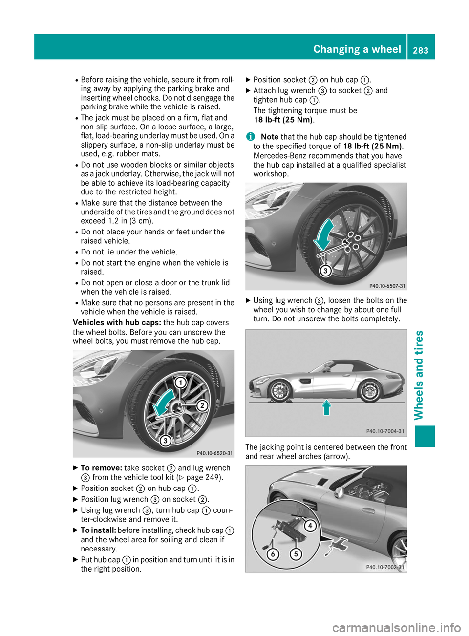
Vehicles with hub caps: the hub cap covers
the wheel bolts. Before you can unscrew the
wheel bolts, you must remove the hub cap. X
To remove: take socket0044and lug wrench
0087 from the vehicle tool kit (Y page 249).
X Position socket 0044on hub cap 0043.
X Position lug wrench 0087on socket 0044.
X Using lug wrench 0087, turn hub cap0043coun-
ter-clockwise and remove it.
X To install: before installing, check hub cap 0043
and the wheel area for soiling and clean if
necessary.
X Put hub cap 0043in position and turn until it is in
the right position. X
Position socket 0044on hub cap 0043.
X Attach lug wrench 0087to socket 0044and
tighten hub cap 0043.
The tightening torque must be
18 lb-ft (25 Nm).
i Note
that the hub cap should be tightened
to the specified torque of 18 lb-ft (25 Nm).
Mercedes-Benz recommends that you have
the hub cap installed at a qualified specialist
workshop. X
Using lug wrench 0087, loosen the bolts on the
wheel you wish to change by about one full
turn. Do not unscrew the bolts completely. The jacking point is centered between the front
and rear wheel arches (arrow). Changing a wheel
283Wheels and tires Z
Page 295 of 298
!
Only MB SummerFit and MB WinterFit
washer fluid should be mixed together. The
spray nozzles may otherwise become
blocked.
Do not use distilled or de-ionized water. Other-
wise, the level sensor may give a false reading.
At temperatures above freezing:
X Fill the washer fluid reservoir with a mixture of
water and windshield washer fluid, e.g. MB
SummerFit.
Add 1 part MB SummerFit to 100 parts water.
At temperatures below freezing:
X Fill the washer fluid reservoir with a mixture of
water and washer fluid, e.g. MB WinterFit.
For the correct mixing ratio refer to the infor-mation on the antifreeze reservoir.
i Add windshield washer fluid, e.g. MB Sum-
merFit or MB WinterFit, to the washer fluid all
year round. Climate control system refrigerant
Important safety notes The instruction label regarding the refrigerant
type used can be found on the radiator cross
member. Further information can be found in
the currently valid service information.
Service work, such as refilling with refrigerant or
replacing component parts, may only be carried out by a qualified specialist workshop. All appli-
cable regulations must be adhered to, SAE
standard J639 included.
Always have work on the climate control system
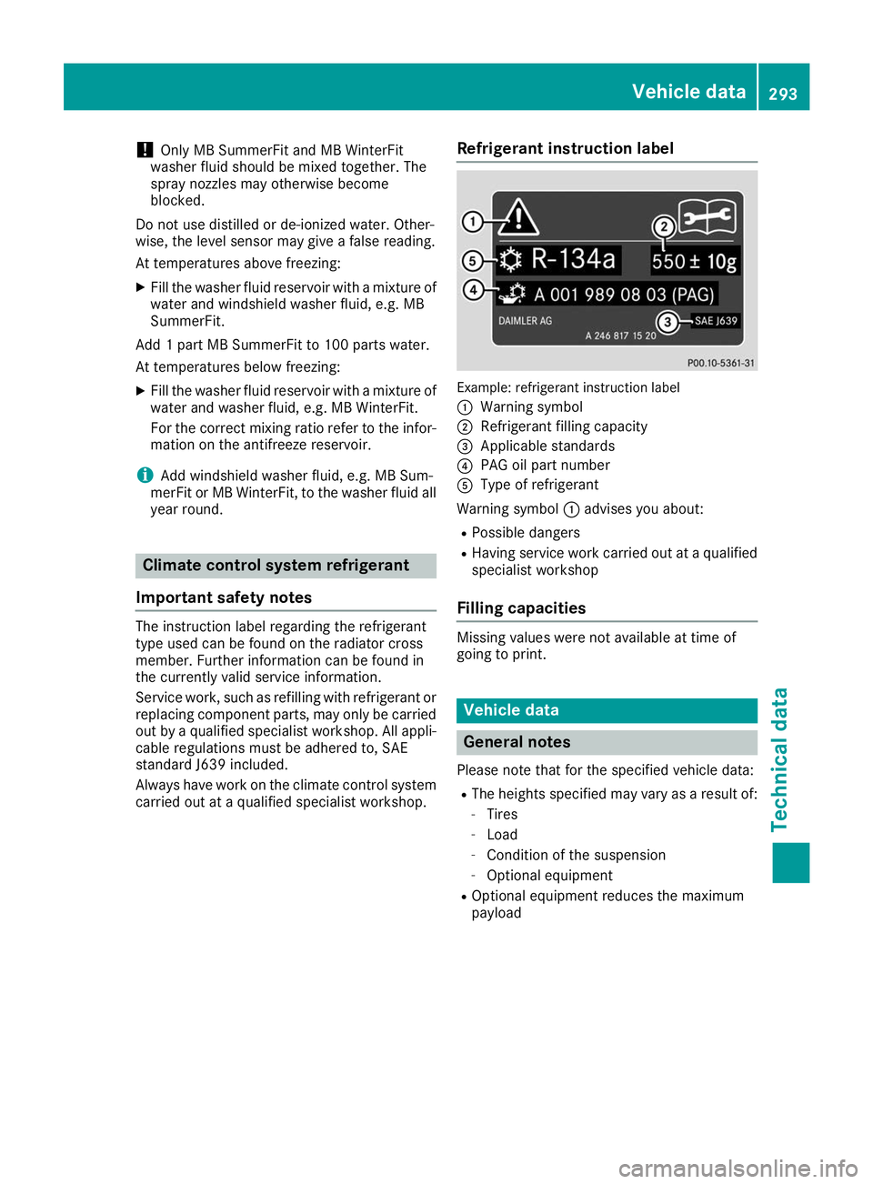
carried out at a qualified specialist workshop. Refrigerant instruction label Example: refrigerant instruction label
0043
Warning symbol
0044 Refrigerant filling capacity
0087 Applicable standards
0085 PAG oil part number
0083 Type of refrigerant
Warning symbol 0043advises you about:
R Possible dangers
R Having service work carried out at a qualified
specialist workshop
Filling capacities Missing values were not available at time of
going to print. Vehicle data
General notes
Please note that for the specified vehicle data:
R The heights specified may vary as a result of:
- Tires
- Load
- Condition of the suspension
- Optional equipment
R Optional equipment reduces the maximum
payload Vehicle data
293Technical data Z