Cluster MERCEDES-BENZ B-Class 2017 W246 Workshop Manual
[x] Cancel search | Manufacturer: MERCEDES-BENZ, Model Year: 2017, Model line: B-Class, Model: MERCEDES-BENZ B-Class 2017 W246Pages: 290, PDF Size: 19.81 MB
Page 199 of 290
Warning/
indicator
lamp
0051 0051
Signal type
Possible causes/consequences and 0050
0050Solutions 00E500BB
00C6004D
0051
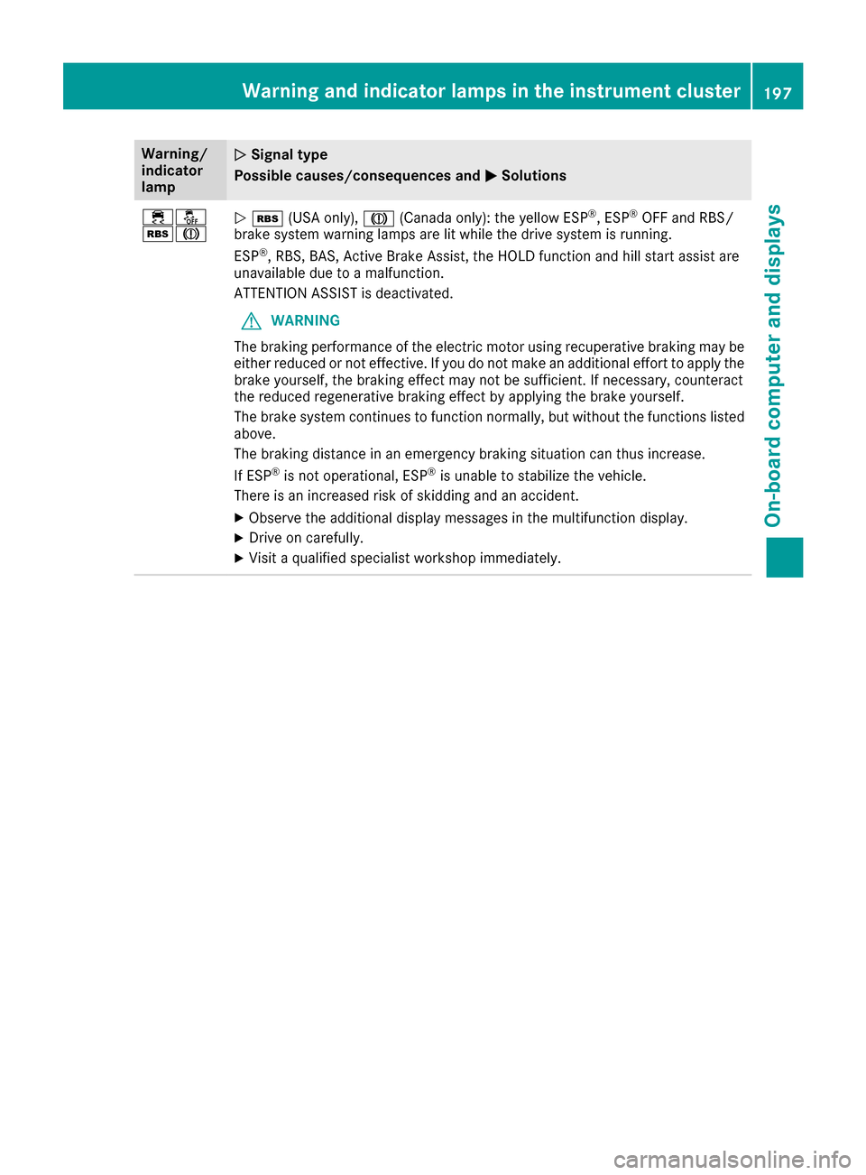
00C6 (USA only), 004D(Canada only): the yellow ESP ®
, ESP ®
OFF and RBS/
brake system warning lamps are lit while the drive system is running.
ESP ®
, RBS, BAS, Active Brake Assist, the HOLD function and hill start assist are
unavailable due to a malfunction.
ATTENTION ASSIST is deactivated.
G WARNING
The braking performance of the electric motor using recuperative braking may be
either reduced or not effective. If you do not make an additional effort to apply the brake yourself, the braking effect may not be sufficient. If necessary, counteract
the reduced regenerative braking effect by applying the brake yourself.
The brake system continues to function normally, but without the functions listed
above.
The braking distance in an emergency braking situation can thus increase.
If ESP ®
is not operational, ESP ®
is unable to stabilize the vehicle.
There is an increased risk of skidding and an accident.
X Observe the additional display messages in the multifunction display.
X Drive on carefully.
X Visit a qualified specialist workshop immediately. Warning and indicator lamps in the instrument cluster
197On-board computer and displays Z
Page 200 of 290
Warning/
indicator
lamp
0051
0051 Signal type
Possible causes/consequences and 0050 0050Solutions 00E500BB
00C6004D
0051
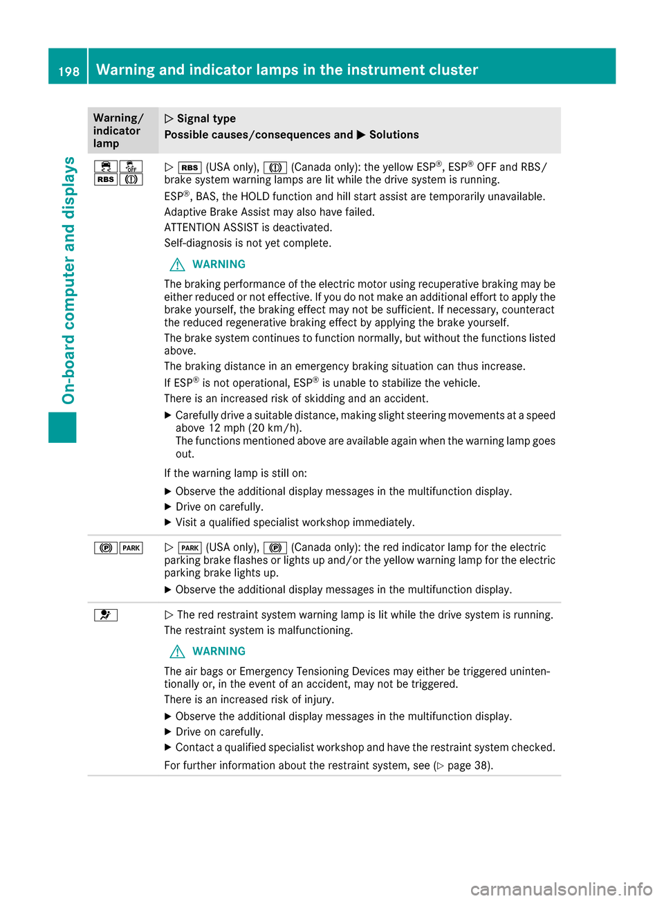
00C6 (USA only), 004D(Canada only): the yellow ESP ®
, ESP ®
OFF and RBS/
brake system warning lamps are lit while the drive system is running.
ESP ®
, BAS, the HOLD function and hill start assist are temporarily unavailable.
Adaptive Brake Assist may also have failed.
ATTENTION ASSIST is deactivated.
Self-diagnosis is not yet complete.
G WARNING
The braking performance of the electric motor using recuperative braking may be
either reduced or not effective. If you do not make an additional effort to apply the brake yourself, the braking effect may not be sufficient. If necessary, counteract
the reduced regenerative braking effect by applying the brake yourself.
The brake system continues to function normally, but without the functions listed
above.
The braking distance in an emergency braking situation can thus increase.
If ESP ®
is not operational, ESP ®
is unable to stabilize the vehicle.
There is an increased risk of skidding and an accident.
X Carefully drive a suitable distance, making slight steering movements at a speed
above 12 mph (20 km/h).
The functions mentioned above are available again when the warning lamp goes
out.
If the warning lamp is still on: X Observe the additional display messages in the multifunction display.
X Drive on carefully.
X Visit a qualified specialist workshop immediately. 00240049
0051
0049 (USA only), 0024(Canada only): the red indicator lamp for the electric
parking brake flashes or lights up and/or the yellow warning lamp for the electric
parking brake lights up.
X Observe the additional display messages in the multifunction display. 0075
0051
The red restraint system warning lamp is lit while the drive system is running.
The restraint system is malfunctioning.
G WARNING
The air bags or Emergency Tensioning Devices may either be triggered uninten-
tionally or, in the event of an accident, may not be triggered.
There is an increased risk of injury.
X Observe the additional display messages in the multifunction display.
X Drive on carefully.
X Contact a qualified specialist workshop and have the restraint system checked.
For further information about the restraint system, see (Y page 38).198
Warning and indicator lamps in the instrument clusterOn-board computer and displays
Page 201 of 290
Drive system
Warning/
indicator
lamp
0051 0051
Signal type
Possible causes/consequences and 0050
0050Solutions 00D9
0051
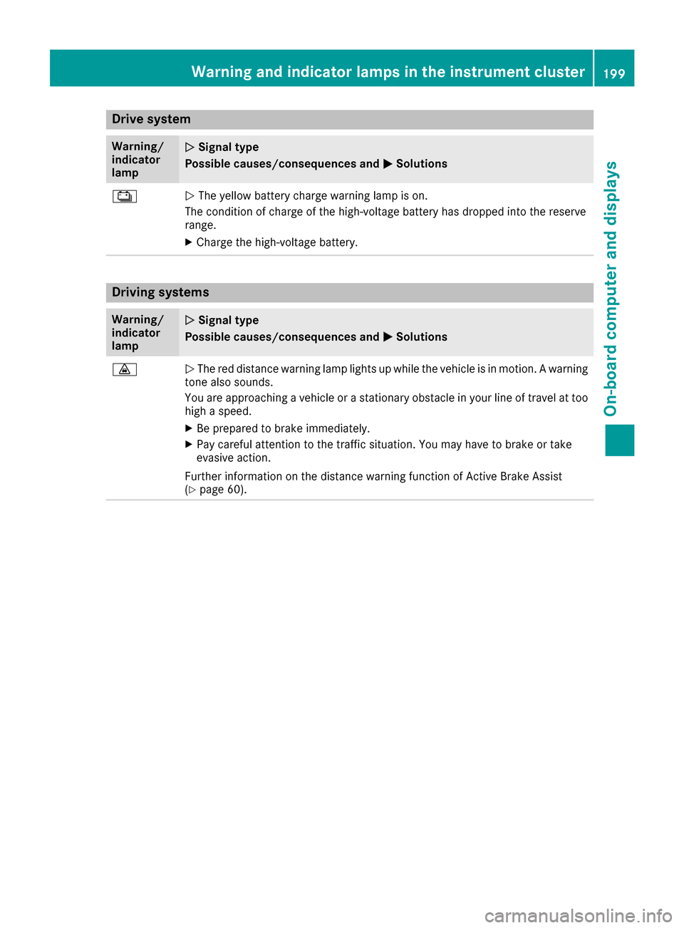
The yellow battery charge warning lamp is on.
The condition of charge of the high-voltage battery has dropped into the reserve
range.
X Charge the high-voltage battery. Driving systems
Warning/
indicator
lamp 0051 0051
Signal type
Possible causes/consequences and 0050
0050Solutions 00BA
0051
The red distance warning lamp lights up while the vehicle is in motion. A warning
tone also sounds.
You are approaching a vehicle or a stationary obstacle in your line of travel at too high a speed.
X Be prepared to brake immediately.
X Pay careful attention to the traffic situation. You may have to brake or take
evasive action.
Further information on the distance warning function of Active Brake Assist
(Y page 60). Wa
rning and indi cator lamps in the instrument cluster
199On-board computer and displays Z
Page 202 of 290
Tires
Warning/
indicator
lamp
0051 0051
Signal type
Possible causes/consequences and 0050
0050Solutions 0077
0051
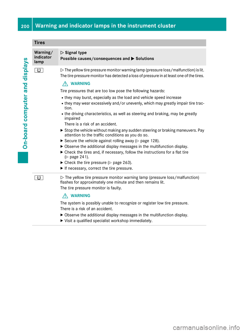
The yellow tire pressure monitor warning lamp (pressure loss/malfunction) is lit.
The tire pressure monitor has detected a loss of pressure in at least one of the tires.
G WARNING
Tire pressures that are too low pose the following hazards: R they may burst, especially as the load and vehicle speed increase
R they may wear excessively and/or unevenly, which may greatly impair tire trac-
tion.
R the driving characteristics, as well as steering and braking, may be greatly
impaired
There is a risk of an accident.
X Stop the vehicle without making any sudden steering or braking maneuvers. Pay
attention to the traffic conditions as you do so.
X Secure the vehicle against rolling away (Y page 128).
X Observe the additional display messages in the multifunction display.
X Check the tires and, if necessary, follow the instructions for a flat tire
(Y page 241).
X Check the tire pressure (Y page 263).
X If necessary, correct the tire pressure. 0077
0051
The yellow tire pressure monitor warning lamp (pressure loss/malfunction)
flashes for approximately one minute and then remains lit.
The tire pressure monitor is faulty.
G WARNING
The system is possibly unable to recognize or register low tire pressure.
There is a risk of an accident.
X Observe the additional display messages in the multifunction display.
X Visit a qualified specialist workshop immediately. 200
Warning and indicator lamps in the instrument clusterOn-board computer and displays
Page 234 of 290
X
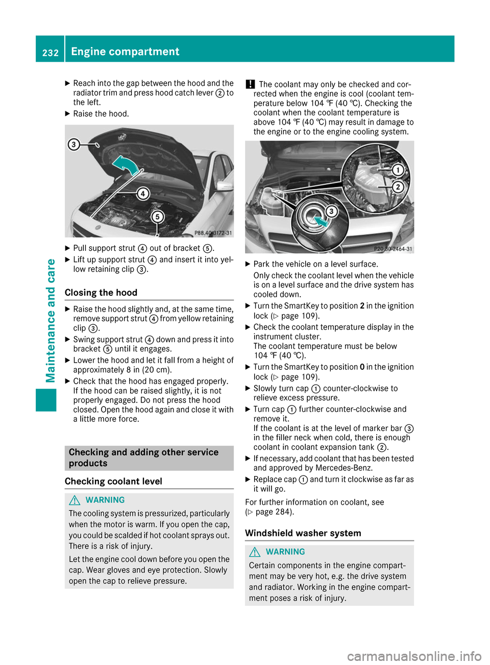
Reach into the gap between the hood and the
radiator trim and press hood catch lever 0044to
the left.
X Raise the hood. X
Pull support strut 0085out of bracket 0083.
X Lift up support strut 0085and insert it into yel-
low retaining clip 0087.
Closing the hood X
Raise the hood slightly and, at the same time,
remove support strut 0085from yellow retaining
clip 0087.
X Swing support strut 0085down and press it into
bracket 0083until it engages.
X Lower the hood and let it fall from a height of
approximately 8 in (20 cm).
X Check that the hood has engaged properly.
If the hood can be raised slightly, it is not
properly engaged. Do not press the hood
closed. Open the hood again and close it with a little more force. Checking and adding other service
products
Checking coolant level G
WARNING
The cooling system is pressurized, particularly when the motor is warm. If you open the cap, you could be scalded if hot coolant sprays out.
There is a risk of injury.
Let the engine cool down before you open the
cap. Wear gloves and eye protection. Slowly
open the cap to relieve pressure. !
The coolant may only be checked and cor-
rected when the engine is cool (coolant tem-
perature below 104 ‡ (40 †).Checking the
coolant when the coolant temperature is
above 104 ‡ (40 †) may result in damage to
the engine or to the engine cooling system. X
Park the vehicle on a level surface.
Only check the coolant level when the vehicle
is on a level surface and the drive system has
cooled down.
X Turn the SmartKey to position 2in the ignition
lock (Y page 109).
X Check the coolant temperature display in the
instrument cluster.
The coolant temperature must be below
104 ‡ (40 †).
X Turn the SmartKey to position 0in the ignition
lock (Y page 109).
X Slowly turn cap 0043counter-clockwise to
relieve excess pressure.
X Turn cap 0043further counter-clockwise and
remove it.
If the coolant is at the level of marker bar 0087
in the filler neck when cold, there is enough
coolant in coolant expansion tank 0044.
X If necessary, add coolant that has been tested
and approved by Mercedes-Benz.
X Replace cap 0043and turn it clockwise as far as
it will go.
For further information on coolant, see
(Y page 284).
Windshield washer system G
WARNING
Certain components in the engine compart-
ment may be very hot, e.g. the drive system
and radiator. Working in the engine compart-
ment poses a risk of injury. 232
Engine compartmentMaintenance and care
Page 245 of 290
TIREFIT kit
Important safety notes TIREFIT is a tire sealant.
You can use TIREFIT to seal punctures of up to
0.16 in (4 mm), particularly those in the tire
tread. You can use TIREFIT at outside tempera-
tures down to 00F84 ‡ (00F820 †). G
WARNING
In the following situations, the tire sealant is
unable to provide sufficient breakdown assis- tance, as it is unable to seal the tire properly:
R there are cuts or punctures in the tire larger
than those mentioned above.
R the wheel rim is damaged.
R you have driven at very low tire pressures or
on a flat tire.
There is a risk of an accident.
Do not drive the vehicle. Contact a qualified
specialist workshop. G
WARNING
The tire sealant is harmful and causes irrita-
tion. It must not come into contact with your
skin, eyes or clothing or be swallowed. Do not inhale TIREFIT fumes. Keep tire sealant away
from children. There is a risk of injury.
If you come into contact with the tire sealant,
observe the following:
R Rinse off the tire sealant from your skin
immediately with water.
R If the tire sealant comes into contact with
your eyes, immediately rinse them thor-
oughly with clean water.
R If tire sealant is swallowed, immediately
rinse your mouth out thoroughly and drink
plenty of water. Do not induce vomiting,
and seek medical attention immediately.
R Immediately change out of clothing which
has come into contact with tire sealant.
R If an allergic reaction occurs, seek medical
attention immediately. !
Residue from the tire sealant may come out
of the filler hose after use. This could cause
stains.
Therefore, place the filler hose in the plastic
bag which contained the TIREFIT kit. H
Environmental note
Have the used tire sealant bottle disposed of
professionally, e.g. at a qualified specialist
workshop.
! Do not operate the tire inflation compressor
for longer than ten minutes at a time without
a break. It may otherwise overheat.
The tire inflation compressor can be operated again once it has cooled down.
Comply with the manufacturer’s safety instruc-
tions on the sticker on the tire inflation com-
pressor.
Using the TIREFIT kit X
Do not remove any foreign objects which have
penetrated the tire, e.g. screws or nails.
X Remove the tire sealant bottle, the accompa-
nying TIREFIT sticker and the tire inflation
compressor from the stowage well under-
neath the cargo compartment floor
(Y page 241).
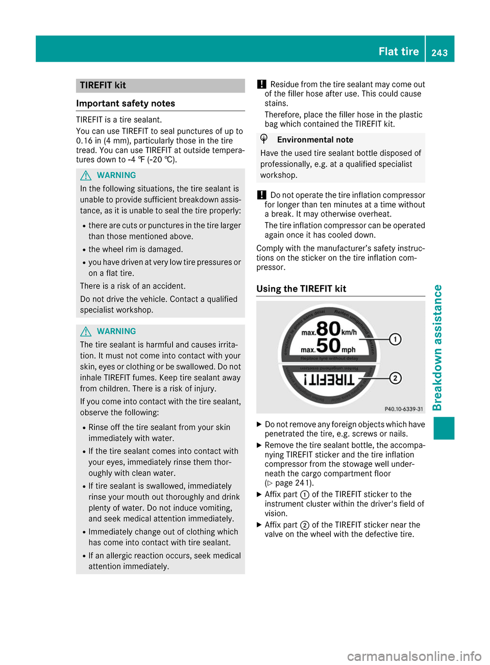
X Affix part 0043of the TIREFIT sticker to the
instrument cluster within the driver's field of
vision.
X Affix part 0044of the TIREFIT sticker near the
valve on the wheel with the defective tire. Flat tire
243Breakdown assistance Z
Page 247 of 290
Tire pressure reached
G
WARNING
A tire temporarily sealed with tire sealant
impairs the driving characteristics and is not
suitable for higher speeds. There is a risk of
accident.
You should therefore adapt your driving style
accordingly and drive carefully. Do not exceed the specified maximum speed with a tire that
has been repaired using tire sealant.
The maximum permissible speed for a tire
sealed with tire sealant is 50 mph (80 km/h).
The upper part of the TIREFIT sticker must be
affixed to the instrument cluster in the driver's
field of vision.
If a tire pressure of 200 kPa (2.0 bar/29 psi) has been attained after ten minutes:
X Switch off the tire inflation compressor.
X Unscrew the filler hose from the valve of the
faulty tire.
Note that tire sealant may escape when you
unscrew the filler hose.
X Stow the tire sealant bottle and the tire infla-
tion compressor.
X Pull away immediately.
X Stop after driving for approximately ten
minutes and check the tire pressure with the
tire inflation compressor.
The tire pressure must now be at least
130 kPa (1.3 bar/19 psi). G
WARNING
If the required tire pressure is not reached
after driving for a short period, the tire is too
badly damaged. The tire sealant cannot repair the tire in this instance. Damaged tires and a
tire pressure that is too low can significantly
impair the vehicle's braking and driving char-
acteristics. There is a risk of accident.
Do not continue driving. Contact a qualified
specialist workshop.
i In cases such as the one mentioned above,
contact an authorized Mercedes-Benz Cen-
ter. Or call 1-800-FOR-MERCedes (in the
USA) or 1-800-387-0100 (in Canada). X
Correct the tire pressure if it is still at least
130 kPa (1.3 bar/19 psi). See the Tire and
Loading Information placard on the driver's
side B-pillar or the tire pressure table in the
charge socket flap for values.
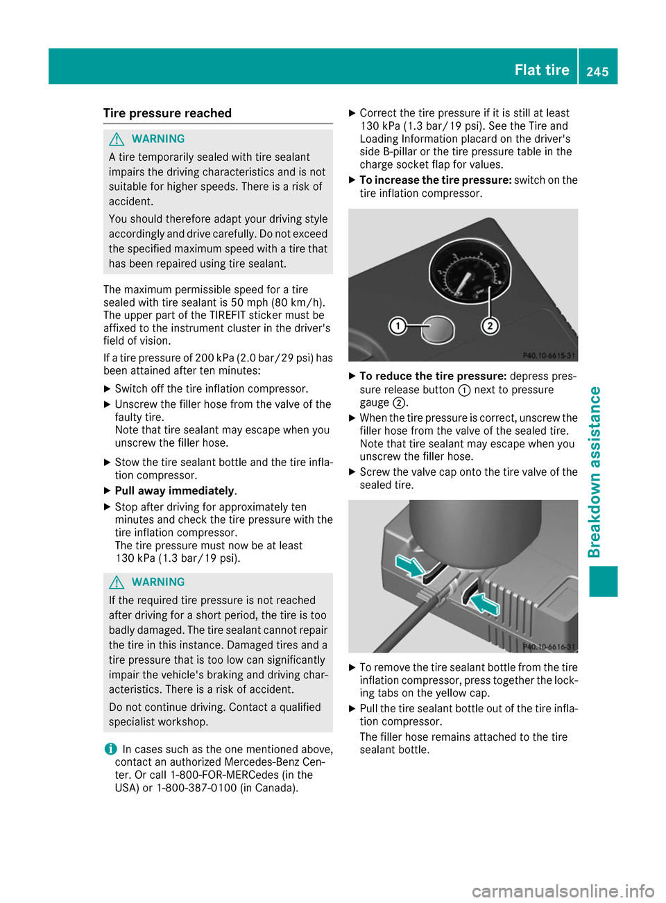
X To increase the tire pressure: switch on the
tire inflation compressor. X
To reduce the tire pressure: depress pres-
sure release button 0043next to pressure
gauge 0044.
X When the tire pressure is correct, unscrew the
filler hose from the valve of the sealed tire.
Note that tire sealant may escape when you
unscrew the filler hose.
X Screw the valve cap onto the tire valve of the
sealed tire. X
To remove the tire sealant bottle from the tire
inflation compressor, press together the lock- ing tabs on the yellow cap.
X Pull the tire sealant bottle out of the tire infla-
tion compressor.
The filler hose remains attached to the tire
sealant bottle. Flat tire
245Breakdown assistance Z
Page 250 of 290
find further information in the separate operat-
ing instructions. Charging the 12‑volt battery
G
WARNING
During charging and jump-starting, explosive
gases can escape from the battery. There is a risk of an explosion.
Particularly avoid fire, open flames, creating
sparks and smoking. Ensure there is sufficient
ventilation while charging and jump-starting.
Do not lean over a battery. G
WARNING
Battery acid is caustic. There is a risk of injury. Avoid contact with skin, eyes or clothing. Do
not inhale any battery gases. Do not lean over
the battery. Keep children away from batter-
ies. Wash away battery acid immediately with
plenty of clean water and seek medical atten- tion. G
WARNING
A discharged battery can freeze at tempera-
tures below freezing point. When jump-start-
ing the vehicle or charging the battery, gases can escape from the battery. There is a risk of
an explosion.
Allow the frozen battery to thaw out before
charging it or jump-starting.
! Only use battery chargers with a maximum
charging voltage of 14.8 V.
! Only
charge the battery using the jump-
starting connection point.
The jump-starting connection point is in the
engine compartment (Y page 249).
X Open the hood.
X Connect the battery charger to the positive
terminal and ground point in the same order
as when connecting the donor battery in the
jump-starting procedure (Y page 249).
If the indicator/warning lamps do not light up in
the instrument cluster at low temperatures, it is very likely that the discharged battery has fro-
zen. In this case you may neither jump-start the vehicle nor charge the battery. The service life of
a thawed-out battery may be shorter. The start-ing characteristics can be impaired, particularly at low temperatures. Have the thawed-out bat-
tery checked at a qualified specialist workshop.
Only charge the installed battery with a battery
charger which has been tested and approved byMercedes-Benz. A battery charger unit specially
adapted for Mercedes-Benz vehicles and tested
and approved by Mercedes-Benz is available as an accessory. It permits the charging of the bat-tery in its installed position. Contact an author-
ized Mercedes-Benz Center for further informa- tion and availability. Read the battery charger's
operating instructions before charging the bat-
tery. High-voltage battery – important
safety notes
G
DANGER
The vehicle's high-voltage electrical system is under high voltage. If you modify components
in the vehicle's high-voltage electrical system
or touch damaged components, you may be
electrocuted. The components in the vehi-
cle's high-voltage electrical system may be
damaged in an accident, although the damage is not visible. There is a risk of fatal injury.
Following an accident, do not touch any high- voltage components and never modify the
vehicle's high-voltage electrical system. Have
the vehicle towed away after an accident and
the vehicle's high-voltage electrical system
checked by a qualified specialist workshop. G
WARNING
In the event of a vehicle fire, the internal pres- sure of the high-voltage battery can exceed a
critical value. In this case flammable gas
escapes through a ventilation valve on the
underbody. The gas can ignite. There is a risk of injury.
Leave the danger zone immediately. Secure
the danger area at a suitable distance, whilst
observing legal requirements. 248
BatteriesBreakdown assistance
Page 252 of 290
R
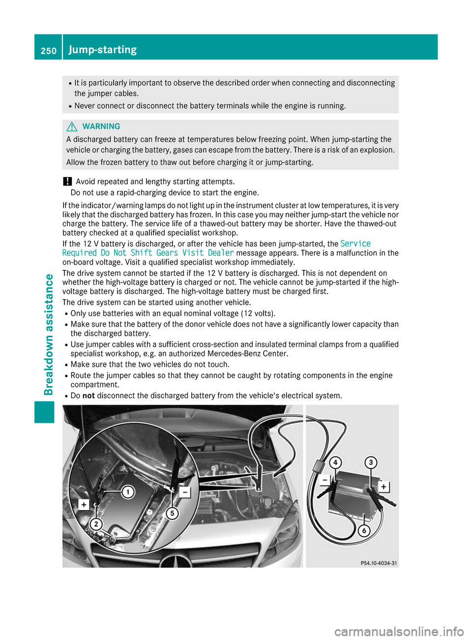
It is particularly important to observe the described order when connecting and disconnecting
the jumper cables.
R Never connect or disconnect the battery terminals while the engine is running. G
WARNING
A discharged battery can freeze at temperatures below freezing point. When jump-starting the
vehicle or charging the battery, gases can escape from the battery. There is a risk of an explosion.
Allow the frozen battery to thaw out before charging it or jump-starting.
! Avoid repeated and lengthy starting attempts.
Do not use a rapid-charging device to start the engine.
If the indicator/warning lamps do not light up in the instrument cluster at low temperatures, it is very likely that the discharged battery has frozen. In this case you may neither jump-start the vehicle norcharge the battery. The service life of a thawed-out battery may be shorter. Have the thawed-out
battery checked at a qualified specialist workshop.
If the 12 V battery is discharged, or after the vehicle has been jump-started, the Service
Service
Required Required Do
DoNot
Not Shift
Shift Gears
GearsVisit
VisitDealer
Dealer message appears. There is a malfunction in the
on-board voltage. Visit a qualified specialist workshop immediately.
The drive system cannot be started if the 12 V battery is discharged. This is not dependent on
whether the high-voltage battery is charged or not. The vehicle cannot be jump-started if the high-
voltage battery is discharged. The high-voltage battery must be charged first.
The drive system can be started using another vehicle. R Only use batteries with an equal nominal voltage (12 volts).
R Make sure that the battery of the donor vehicle does not have a significantly lower capacity than
the discharged battery.
R Use jumper cables with a sufficient cross-section and insulated terminal clamps from a qualified
specialist workshop, e.g. an authorized Mercedes-Benz Center.
R Make sure that the two vehicles do not touch.
R Route the jumper cables so that they cannot be caught by rotating components in the engine
compartment.
R Do not disconnect the discharged battery from the vehicle's electrical system. 250
Jump-startingBreakdown assistance
Page 266 of 290
Important safety notes
G
WARNING
Each tire, including the spare (if provided),
should be checked at least once every two
weeks when cold and inflated to the pressure recommended by the vehicle manufacturer
on the Tire and Loading Information placard
on the driver's door B-pillar or the tire pres-
sure label on the inside of the fuel filler flap. If
your vehicle has tires of a different size than
the size indicated on the Tire and Loading
Information placard or, if available, the tire
pressure label, you should determine the
proper tire pressure for those tires.
As an added safety feature, your vehicle has
been equipped with a tire pressure monitoring system (TPMS) that illuminates a low tire pres-
sure telltale when one or more of your tires
are significantly underinflated. Accordingly,
when the low tire pressure telltale lights up,
you should stop and check your tires as soon
as possible, and inflate them to the proper
pressure. Driving on a significantly underin-
flated tire causes the tire to overheat and can
lead to tire failure.
Underinflation also reduces fuel efficiency
and tire tread life, and may affect the vehicle's handling and stopping ability. Please note that the TPMS is not a substitute for proper tire
maintenance, and it is the driver's responsi-
bility to maintain correct tire pressure, even if
underinflation has not reached the level to
trigger illumination of the TPMS low tire pres-
sure telltale.
Your vehicle has also been equipped with a
TPMS malfunction indicator to indicate when
the system is not operating properly. The
TPMS malfunction indicator is combined with
the low tire pressure telltale. When the sys-
tem detects a malfunction, the warning lamp
will flash for approximately a minute and then remain continuously illuminated. This
sequence will be repeated every time the vehi- cle is started as long as the malfunction
exists. When the malfunction indicator is illu- minated, the system may not be able to detect
or signal low tire pressure as intended.
TPMS malfunctions may occur for a variety of reasons, including the installation of incom-
patible replacement or alternate tires or
wheels on the vehicle that prevent the TPMS
from functioning properly. Always check the
TPMS malfunction telltale after replacing one or more tires or wheels on your vehicle to
ensure that the replacement or alternate Tires and wheels allow the TPMS to continue to
function properly.
It is the driver's responsibility to set the tire
pressure to that recommended for cold tires
which is suitable for the operating situation
(Y page 260). Note that the correct tire pressure
for the current operating situation must first be taught-in to the tire pressure monitor. If a sub-
stantial loss of pressure occurs, the warning
threshold for the warning message is aligned to
the taught-in reference values. Restart the tire
pressure monitor after adjusting the pressure of the cold tires (Y page 265). The current pres-
sures are saved as new reference values. As a
result, a warning message will appear if the tire
pressure drops significantly.
The tire pressure monitor does not warn you of
an incorrectly set tire pressure. Observe the
notes on the recommended tire pressure
(Y page 260).
The tire pressure monitor is not able to warn you of a sudden loss of pressure, e.g. if the tire is
penetrated by a foreign object. In the event of a
sudden loss of pressure, bring the vehicle to a
halt by braking carefully. Avoid abrupt steering
movements.
The tire pressure monitor has a yellow warning
lamp in the instrument cluster for indicating
pressure loss or a malfunction. Whether the
warning lamp flashes or lights up indicates
whether a tire pressure is too low or the tire
pressure monitor is malfunctioning:
R if the warning lamp is lit continuously, the tire
pressure on one or more tires is significantly
too low. The tire pressure monitor is not mal- functioning.
R if the warning lamp flashes for around a
minute and then remains lit constantly, the
tire pressure monitor is malfunctioning.
In addition to the warning lamp, a message
appears in the multifunction display. Observe 264
Tire pressureWheels and ti
res