tow MERCEDES-BENZ B-Class 2017 W246 Workshop Manual
[x] Cancel search | Manufacturer: MERCEDES-BENZ, Model Year: 2017, Model line: B-Class, Model: MERCEDES-BENZ B-Class 2017 W246Pages: 290, PDF Size: 19.81 MB
Page 226 of 290
Mercedes-Benz Customer Assistance Center
at 1-800-FOR-MERCedes (1-800-367-6372)
or 1-866-990-9007
You will be asked for your password.
X Return to your vehicle at the time agreed upon
with the Mercedes-Benz Customer Assis-
tance Center.
Alternatively, the vehicle can be opened via:
R the Internet, under the "Owners Online" sec-
tion
R telephone applications (e.g. for iPhone ®
,
Android™)
To do this, you will need your identification num-
ber and password.
Vehicle remote closing The vehicle remote-closing feature can be used
when you have forgotten to lock the vehicle and
you are no longer nearby.
The vehicle can then be locked by the Mercedes-
Benz Customer Assistance Center.
The vehicle can be immediately remotely locked within four days of the ignition being turned off.
After this time, remote closing may be delayed
by 15 to 60 minutes. After 30 days the vehicle
can no longer be valet locked remotely.
The vehicle remote closing feature is available if the relevant mobile phone network is available
and a data connection is possible.
X Contact the following service hotlines:
Mercedes-Benz Customer Assistance Center
at 1-800-FOR-MERCedes (1-800-367-6372)
or 1-866-990-9007
You will be asked for your password.
The next time you are inside the vehicle and you switch on the ignition, the Doors Locked
Doors Locked
Remotely Remotely message appears in the multifunction
display.
Alternatively, the vehicle can be locked via:
R the Internet, under the "Owners Online" sec-
tion
R telephone applications (e.g. for iPhone ®
,
Android™)
To do this, you will need your identification num- ber and password. Stolen vehicle recovery service If your vehicle has been stolen:
X Notify the police.
The police will issue a numbered incident
report.
X This number will be forwarded to the
Mercedes-Benz Customer Assistance Center
together with your PIN.
The Mercedes-Benz Customer Assistance
Center then tries to locate the system. The
Mercedes-Benz Customer Assistance Center
contacts you and the local law enforcement
agency if the vehicle is located.
However, only the law enforcement agency is informed of the location of the vehicle.
If the anti-theft alarm system is activated for
longer than 30 seconds, the Mercedes-Benz
Customer Assistance Center is automatically
notified.
Vehicle Health Check With the Vehicle Health Check, the Customer
Assistance Center can provide improved sup-
port for problems with your vehicle. During an
existing call, vehicle data is transferred to the
Customer Assistance Center.
The customer service representative can use
the received data to decide what kind of assis-
tance is required. You are then, for example,
guided to the nearest Mercedes-Benz Service
Center or a recovery vehicle is called.
If vehicle data needs to be transferred during an MB Info call or a Roadside Assistance call, this is
initiated by the Customer Assistance Center.
The Roadside Assistance Connected Roadside Assistance Connected mes-
sage appears in the display. If the Vehicle Health
Check can be started, the Request
Requestfor
forVehi‐
Vehi‐
cle Diagnostics Received Start vehi‐
cle Diagnostics Received Start vehi‐
cle diagnostics? cle diagnostics? message appears in the
display.
X Press the Yes
Yesbutton to confirm the message.
X When the Vehicle Diagnostics Please
Vehicle Diagnostics Please
Start Ignition
Start Ignition message appears: turn the
SmartKey to position 2in the ignition lock
(Y page 109).
X If the Please follow the instructions
Please follow the instructions
received
received by
byphone
phone and
andmove
move your
yourvehi‐
vehi‐
cle to a safe position.
cle to a safe position. message
appears: please follow the instructions 224
FeaturesStowage and features
Page 227 of 290
received by phone and move your vehicle to a
safe position.
The message in the display disappears.
The vehicle operating state check begins.
During this procedure, you will see the Vehi‐
Vehi‐
cle Diagnostics Active cle Diagnostics Active message.
If you select Cancel
Cancel, the Vehicle Health
Check is canceled completely.
When the check is complete, the Sending
Sending
vehicle diagnostics data. (Voice con‐
vehicle diagnostics data. (Voice con‐
nection may be interrupted during nection may be interrupted during
data data transfer)
transfer) message appears. The vehicle
data can now be sent.
X Press the OK
OK button to confirm the message.
The voice connection with the Customer
Assistance Center is terminated.
The Vehicle Diagnostics: Transfer‐ Vehicle Diagnostics: Transfer‐
ring Data...
ring Data... message appears.
The vehicle data is sent to the Customer
Assistance Center.
Depending on what the customer service rep-
resentative agreed with you, the voice connec-
tion is re-established after the transfer is com-
plete. If necessary, you will be contacted at a
later time by another means, e.g. by e-mail or
phone.
Another function of the Vehicle Health Check is
the transfer of service data to the Customer
Assistance Center. If a service is due, the display shows a message to this effect together with
information about any special offers at your
workshop.
This information can also be called up under
"Owners Online" at http://www.mbusa.com.
Information on the data stored in the vehicle
(Y page 28).
Information on Roadside Assistance
(Y page 24).
Downloading routes Downloading routes allows you to transfer and
save predefined routes in the navigation sys-
tem.
A route can be prepared and sent by either a
customer service representative or under "Own- ers Online" at http://www.mbusa.com.
Each route can include up to four way points.
Once a route has been received by the naviga-
tion system, you will see the Do
Do you you want
want to
to
start route guidance? Destination start route guidance? Destination
Received destination has been saved Received destination has been saved in "Previous destinations". in "Previous destinations".
message on
the multimedia system display.
The route is saved.
X To start route guidance: selectYes Yes.
An overview of the route is shown in the dis-
play.
If you select No No, the saved route can be called
up later in the navigation menu.
X Select Start
Start.
Route guidance starts.
Downloaded and saved routes can be called up again.
Speed alert You can define the upper speed limit, which
must not be exceeded by the vehicle.
If this selected speed is exceeded by the vehicle,
a message will be sent to the Customer Assis-
tance Center. The Customer Assistance Center
then forwards this information to you.
You can select the way in which you receive this information beforehand. Possible options
include text message, e-mail or an automated
call.
The data you receive contains the following
information:
R the location where the speed limit was excee-
ded
R the time at which the speed limit was excee-
ded
R the selected speed limit which was exceeded
Geo fencing Geo fencing allows you to select areas which the
vehicle should not enter or leave. You will be
informed if the vehicle crosses the boundaries
of the selected areas. You can select the way inwhich you receive this information beforehand.
Possible options include text message, e-mail or
an automated call.
The area can be determined as either a circle or a polygon with a maximum of ten corners. You
can specify up to ten areas simultaneously. Dif- ferent settings are possible for each area.
These settings can be called up under "Owners
Online" at http://www.mbusa.com.
Alternatively, you can trigger an MB Info call and
inform the customer service representative that
you wish to activate geo fencing. Features
225Stowage and features Z
Page 228 of 290
Currently inactive areas can be activated by text
message.
Triggering the vehicle alarm With this function, you can trigger the vehicle's
panic alarm via text message. An alarm sounds
and the exterior lighting flashes. Depending on
the setting, the panic alarm lasts five or ten sec-
onds. Afterwards, the alarm switches off. Garage door opener
General notes The HomeLink
®
garage door opener integrated
in the rear-view mirror allows you to operate up to three different door and gate systems.
Use the integrated garage door opener only on
garage doors that:
R have safety stop and reverse features and
R meet current U.S. federal safety standards
Once programed, the integrated garage door
opener in the rear-view mirror will assume the
function of the garage door system's remote
control. Please also read the operating instruc-
tions for the garage door system.
When programming a garage door opener, park
the vehicle outside the garage. Do not leave the engine running while programming.
Certain garage door drives are incompatible
with the integrated garage door opener. If you
have difficulty programing the integrated garage
door opener, contact a Mercedes-Benz Service
Center.
Alternatively, you can call the following tele-
phone assistance services:
R USA: Mercedes-Benz Customer Assistance
Center at 1-800-FOR-MERCedes
R Canada: Customer Service at
1-800-387-0100
R HomeLink ®
hotline 1-800-355-3515 (free of
charge)
More information on HomeLink ®
and/or com-
patible products is also available online at
http://www.homelink.co m.
Notes on the declaration of conformity
(Y page 26).
USA: FCC ID: CB2HMIHL4
Canada: IC: 279B-HMIHL4 Important safety notes G
WARNING
When you operate or program the garage door with the integrated garage door opener, per-
sons in the range of movement of the garage
door can become trapped or struck by the
garage door. There is a risk of injury.
When using the integrated garage door
opener, always make sure that nobody is
within the range of movement of the garage
door.
Programming Programming the buttons
Pay attention to the "Important safety notes"
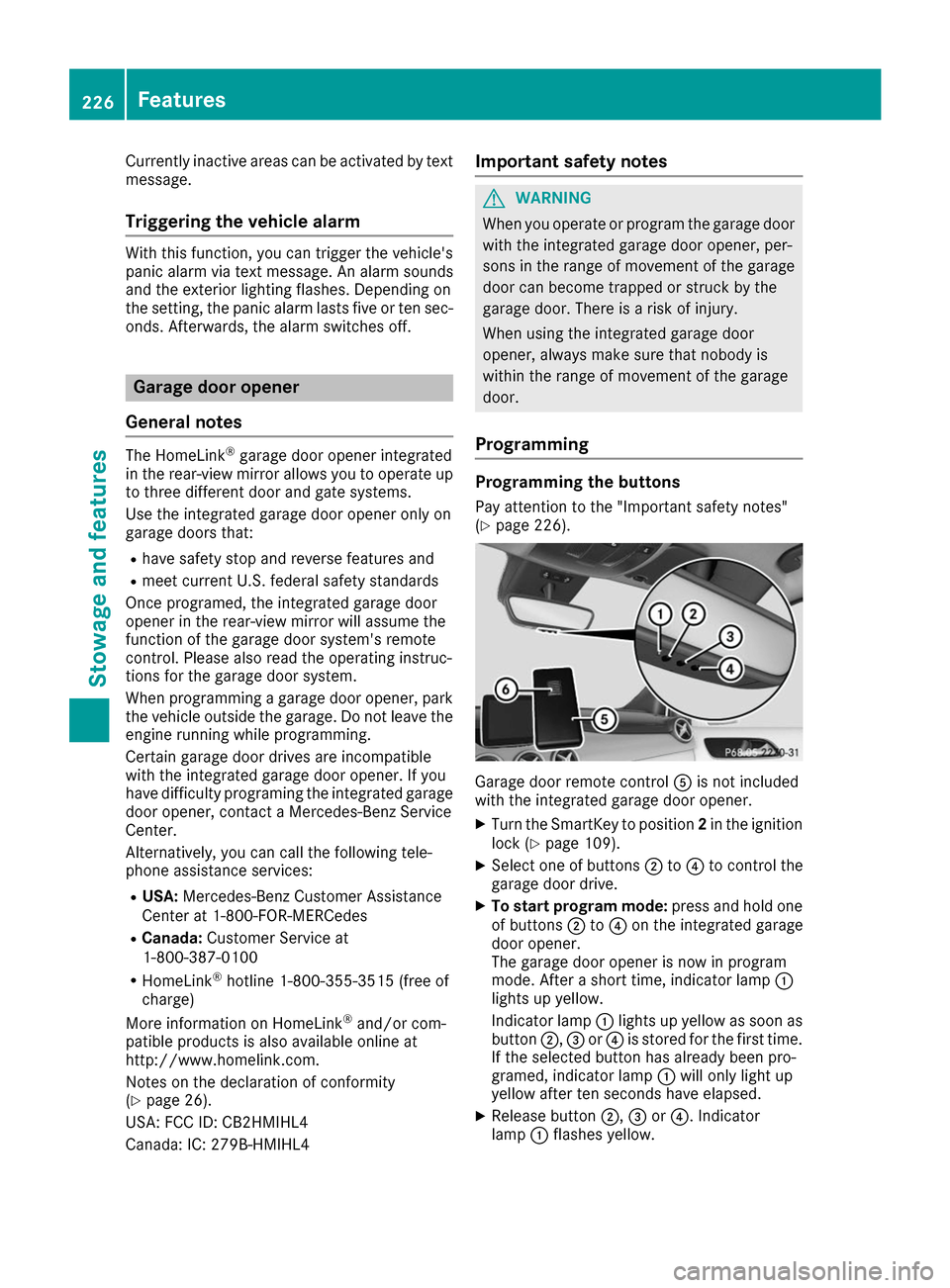
(Y page 226). Garage door remote control
0083is not included
with the integrated garage door opener.
X Turn the SmartKey to position 2in the ignition
lock (Y page 109).
X Select one of buttons 0044to0085 to control the
garage door drive.
X To start program mode: press and hold one
of buttons 0044to0085 on the integrated garage
door opener.
The garage door opener is now in program
mode. After a short time, indicator lamp 0043
lights up yellow.
Indicator lamp 0043lights up yellow as soon as
button 0044,0087or0085 is stored for the first time.
If the selected button has already been pro-
gramed, indicator lamp 0043will only light up
yellow after ten seconds have elapsed.
X Release button 0044,0087or0085. Indicator
lamp 0043flashes yellow. 226
FeaturesStowage and features
Page 229 of 290
X
To program the remote control: point
garage door remote control 0083towards but-
tons 0044to0085 on the rear-view mirror at a dis-
tance of 2to 8 in (5 to 20 cm).
X Press and hold button 0084on remote control
0083 until indicator lamp 0043lights up green.
When indicator lamp 0043lights up green: pro-
gramming is finished.
When indicator lamp 0043flashes green: pro-
gramming was successful. The next step is to synchronize the rolling code (Y page 227).
X Release button 0084on remote control 0083for
the garage door drive system.
If indicator lamp 0043lights up red: repeat the
programing procedure for the corresponding
button on the rear-view mirror. When doing
so, vary the distance between remote control 0083 and the rear-view mirror.
The required distance between remote con-
trol 0083and the integrated garage door opener
depends on the garage door drive system.
Several attempts might be necessary. You
should test every position for at least
25 seconds before trying another position.
Synchronizing the rolling code
Pay attention to the "Important safety notes"
(Y page 226).
If the garage door system uses a rolling code,
you will also have to synchronize the garage
door system with the integrated garage door
opener in the rear-view mirror. To do this you will
need to use the programming button on the door
drive control panel. The programming button
may be located in different places depending on the manufacturer. It is usually located on the
door drive unit on the garage ceiling.
Familiarize yourself with the garage door drive
operating instructions, e.g. under "Program-
ming additional remote controls", before carry-
ing out the following steps.
Your vehicle must be within reach of the garage
door or gate opener drive. Make sure that nei-
ther your vehicle nor any persons/objects are
present within the sweep of the door or gate.
X Turn the SmartKey to position 2in the ignition
lock (Y page 109).
X Get out of the vehicle.
X Press the programming button on the door
drive unit.
Usually, you now have 30 second sto initiate
the next step. X
Get into the vehicle.
X Press previously programed button 0044,0087
or 0085 on the integrated garage door opener
repeatedly and in quick succession until the
door closes.
The rolling code synchronization is then com- plete.
Notes on programming the remote con-
trol
Canadian radio frequency laws require a "break"
(or interruption) of the transmission signals
after broadcasting for a few seconds. Therefore, these signals may not last long enough for the
integrated garage door opener. The signal is not
detected during programming. Comparable with Canadian law, some U.S. garage door openers
also feature a "break".
Proceed as follows:
R if you live in Canada
R if you have difficulties programming the
garage door opener (regardless of where you
live) as you follow the programming steps.
X Press and hold one of buttons 0044to0085 on the
integrated garage door opener.
After a short time, indicator lamp 0043lights up
yellow.
X Release the button.
Indicator lamp 0043flashes yellow.
X Press button 0084of garage door remote con-
trol 0083for two seconds, then release it for two
seconds.
X Press button 0084again for two seconds.
X Repeat this sequence on button 0084of remote
control 0083until indicator lamp 0043lights up
green.
When indicator lamp 0043lights up green: pro-
gramming is finished.
When indicator lamp 0043flashes green: pro-
gramming was successful. The next step is to
synchronize the rolling code.
X Release button 0084of remote control 0083of the
garage door drive.
If indicator lamp 0043lights up red: repeat the
programming process for the corresponding
button on the rear-view mirror. When doing
so, vary the distance between remote control 0083 and the rear-view mirror.
The required distance between remote con-
trol 0083and the integrated garage door opener
depends on the garage door drive system.
Several attempts might be necessary. You Features
227Stowage an d features Z
Page 230 of 290
should test every position for at least
25 seconds before trying another position.
Problems when programming If you are experiencing problems programming
the integrated garage door opener on the rear-
view mirror, take note of the following instruc-
tions:
R Check the transmitter frequency used by
garage door drive remote control 0083and
whether it is supported. The transmitter fre-
quency can usually be found on the back of
remote control 0083for the garage door drive.
The integrated garage door opener is com-
patible with devices that have units which
operate in the frequency range of 280 to
433 MHz.
R Replace the batteries in garage door remote
control 0083. This increases the likelihood that
garage door remote control 0083will transmit a
strong and precise signal to the integrated
garage door opener.
R When programming, hold remote control 0083
at varying distances and angles from but-
tons 0044to0085 which you are programming. Try
various angles at a distance between 2and
8 inches (5to 20 cm) or at the same angle but at varying distances.
R If another remote control 0083is available for
the same garage door drive, repeat the same
programming steps with this remote control
0083. Before performing these steps, make sure
that new batteries have been installed in
garage door drive remote control 0083.
R Note that some remote controls only transmit
for a limited amount of time (the indicator
lamp on the remote control goes out). Press
button 0084on remote control 0083again before
transmission ends.
R Align the antenna cable of the garage door
opener unit. This can improve signal recep-
tion/transmission.
Opening/closing the garage door After it has been programmed, the integrated
garage door opener performs the function of the
garage door system remote control. Please also read the operating instructions for the garage
door system. X
Turn the SmartKey to position 2in the ignition
lock (Y page 109).
X Press button 0044,0087or0085 which you have
programmed to operate the garage door.
Garage door system with a fixed code: indi-
cator lamp 0043lights up green.
Garage door system with a rolling code: indi-
cator lamp 0043flashes green.
The transmitter will transmit a signal as long
as the button is pressed. The transmission is
halted after a maximum of ten seconds and
indicator lamp 0043lights up yellow.
X Press button 0044,0087or0085 again if necessary.
Clearing the memory Make sure that you clear the memory of the
integrated garage door opener before selling the vehicle.
X Turn the SmartKey to position 2in the ignition
lock (Y page 109).
X Press and hold buttons 0044and 0085.
The indicator lamp initially lights up yellow
and then green.
X Release buttons 0044and 0085.
The memory of the integrated garage door
opener in the rear-view mirror is cleared. Compass
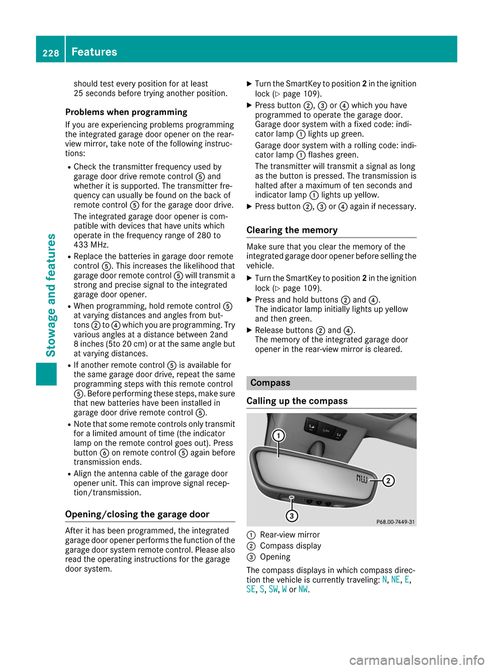
Calling up the compass 0043
Rear-view mirror
0044 Compass display
0087 Opening
The compass displays in which compass direc-
tion the vehicle is currently traveling: N N,NE
NE, E
E,
SE
SE, S
S,SW
SW, W
Wor NW
NW. 228
FeaturesStowage and features
Page 231 of 290
To receive a correct compass display reading,
the magnetic field zone must be set and the
compass calibrated.
Setting the compass X
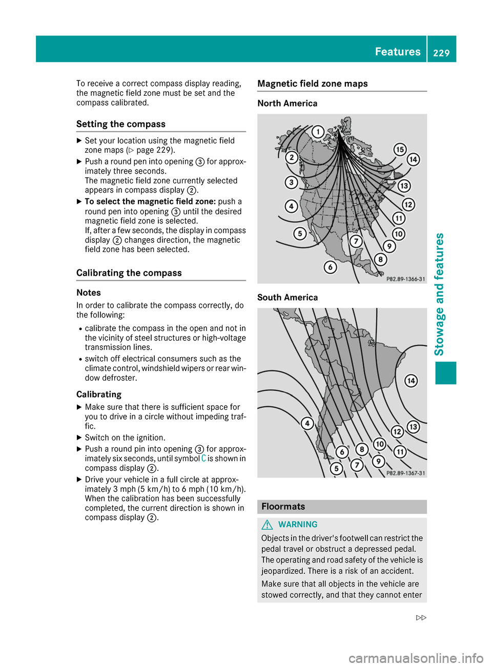
Set your location using the magnetic field
zone maps (Y page 229).
X Push a round pen into opening 0087for approx-
imately three seconds.
The magnetic field zone currently selected
appears in compass display 0044.
X To select the magnetic field zone: push a
round pen into opening 0087until the desired
magnetic field zone is selected.
If, after a few seconds, the display in compass
display 0044changes direction, the magnetic
field zone has been selected.
Calibrating the compass Notes
In order to calibrate the compass correctly, do
the following:
R calibrate the compass in the open and not in
the vicinity of steel structures or high-voltage
transmission lines.
R switch off electrical consumers such as the
climate control, windshield wipers or rear win-
dow defroster.
Calibrating
X Make sure that there is sufficient space for
you to drive in a circle without impeding traf-
fic.
X Switch on the ignition.
X Push a round pin into opening 0087for approx-
imately six seconds, until symbol C
C is shown in
compass display 0044.
X Drive your vehicle in a full circle at approx-
imately 3 mph (5 km/h) to 6 mph (10 km/h).
When the calibration has been successfully
completed, the current direction is shown in
compass display 0044. Magnetic field zone maps North America
South America
Floormats
G
WARNING
Objects in the driver's footwell can restrict the pedal travel or obstruct a depressed pedal.
The operating and road safety of the vehicle is
jeopardized. There is a risk of an accident.
Make sure that all objects in the vehicle are
stowed correctly, and that they cannot enter Features
229Stowage an d features
Z
Page 236 of 290
Information about Service
Resetting the ASSYST PLUS service
interval display !
If the ASSYST PLUS service interval display
has been inadvertently reset, this setting can
be corrected at a qualified specialist work-
shop.
Have service work carried out as described in the Maintenance Booklet. This may otherwise
lead to increased wear and damage to the
major assemblies or the vehicle.
A qualified specialist workshop, e.g. an author-
ized Mercedes-Benz Center, will reset the
ASSYST PLUS service interval display after the
service work has been carried out. You can also obtain further information on maintenance
work, for example.
Special service requirements The specified maintenance interval takes only
the normal operation of the vehicle into
account. Service work will need to be performed
more often if the vehicle is operated under ardu-
ous conditions or increased loads. This can be
the case, for example, when driving frequently in mountainous areas or on poor road surfaces.
In these or similar operating conditions have the interior filter, for example, changed more fre-
quently. Under arduous operating conditions,
the tires must be checked more often. Further
information can be obtained at a qualified spe-
cialist workshop, e.g. an authorized Mercedes-
Benz Center.
Driving abroad An extensive Mercedes-Benz Service network is
also available in other countries. You can obtain further information from any authorized
Mercedes-Benz Center. Care
General notes
H
Environmental note
Dispose of empty packaging and cleaning
cloths in an environmentally responsible man- ner. !
For cleaning your vehicle, do not use any of
the following:
R dry, rough or hard cloths
R abrasive cleaning agents
R solvents
R cleaning agents containing solvents
Do not scrub.
Do not touch the surfaces or protective films
with hard objects, e.g. a ring or ice scraper.
You could otherwise scratch or damage the
surfaces and protective film.
! Do not park your vehicle for a long period of
time directly after cleaning, particularly after
cleaning the wheel rim with wheel cleaner.
Wheel cleaner can lead to the increased cor-
rosion of the brake discs and pads. Therefore,
drive for a few minutes after cleaning. By
heating up the brakes, the brake discs and
pads dry. The vehicle can then be parked for a long period of time.
Regular care of your vehicle is a condition for
retaining the quality in the long term.
Use care products and cleaning agents recom-
mended and approved by Mercedes-Benz. Washing the vehicle and cleaning the
paintwork
Automatic car wash G
WARNING
Braking efficiency is reduced after washing
the vehicle. There is a risk of an accident.
After the vehicle has been washed, brake
carefully while paying attention to the traffic
conditions until full braking power is restored.
! If the HOLD function is activated, the vehicle
brakes automatically in certain situations.
To prevent damage to the vehicle, deactivate the HOLD function in the following or other
similar situations:
R when towing the vehicle
R in the car wash
! Never clean your vehicle in a Touchless
Automatic Car Wash as these use special
cleaning agents. These cleaning agents can
damage the paintwork or plastic parts. 234
CareMaintenance and care
Page 237 of 290
!
When washing your vehicle in a tow-through
car wash, make sure that the selector lever is
in position N, otherwise the vehicle could be
damaged.
! Make sure that:
R the side windows are fully closed.
R the ventilation/heating is switched off (the
OFF button has been pressed/the airflow
control is set to position 0).
R the windshield wiper switch is at position 0.
The vehicle may otherwise be damaged.
You can wash the vehicle in an automatic car
wash from the very start.
If the vehicle is very dirty, pre-wash it before
cleaning it in an automatic car wash.
After using an automatic car wash, wipe off wax from the windshield and the wiper blades. This
will prevent smears and reduce wiping noises
caused by residue on the windshield.
Washing by hand In some countries, washing by hand is only
allowed at specially equipped washing bays.
Observe the legal requirements in each country.
X Do not use hot water and do not wash the
vehicle in direct sunlight.
X Use a soft sponge to clean.
X Use a mild cleaning agent, such as a car
shampoo approved by Mercedes-Benz.
X Thoroughly hose down the vehicle with a gen-
tle jet of water.
X Do not point the water jet directly towards the
air inlet.
X Use plenty of water and rinse out the sponge
frequently.
X Rinse the vehicle with clean water and dry
thoroughly with a chamois.
X Do not let the cleaning agent dry on the paint-
work.
Carefully remove all deposits of road salt as
soon as possible when driving in winter.
Power washers G
WARNING
The water jet from a circular jet nozzle (dirt
blasters) can cause invisible exterior damage to the tires or chassis components. Compo- nents damaged in this way may fail unexpect-
edly. There is a risk of an accident.
Do not use power washers with circular jet
nozzles to clean the vehicle. Have damaged
tires or chassis components replaced imme-
diately.
! Always maintain a distance of at least
11.8 in (30 cm) between the vehicle and the
power washer nozzle. Information about the
correct distance is available from the equip-
ment manufacturer.
Move the power washer nozzle around when
cleaning your vehicle.
Do not aim directly at any of the following:
R Tires
R Door gaps, roof gaps, joints, etc.
R Electrical components
R Battery
R Connectors
R Lamps
R Seals
R Trim
R Ventilation slots
Damaged seals or electrical components can
lead to leaks or failures.
! Vehicles with decorative film: parts of your
vehicle are covered with a decorative film.
Maintain a distance of at least 27.5 in (70 cm)
between the parts of the vehicle covered with
the film and the nozzle of the high pressure
cleaner.
Information about the correct distance is
available from the equipment manufacturer.
Move the power washer nozzle around when
cleaning your vehicle.
Cleaning the paintwork !
Do not affix:
R stickers
R films
R magnetic plates or similar items
to painted surfaces. You could otherwise
damage the paintwork.
Scratches, corrosive deposits, areas affected by
corrosion and damage caused by inadequate Care
235Maintenance and care Z
Page 243 of 290
Where will I find...?
Vehicle tool kit
General notes Vehicles with a TIREFIT kit: the TIREFIT kit is
located in the stowage well under the cargo
compartment floor.
Vehicles with a tire-change tool kit: the tire-
change tool kit is in the stowage well under the
cargo compartment floor.
Apart from certain country-specific variations,
the vehicles are not equipped with a tire-change tool kit. Some tools for changing a wheel are
specific to the vehicle. For more information on
which tire changing tools are required and
approved to perform a wheel change on your
vehicle, consult a qualified specialist workshop.
Tools required for changing a wheel may
include, for example:
R Jack
R Wheel chock
R Lug wrench
R Alignment bolt
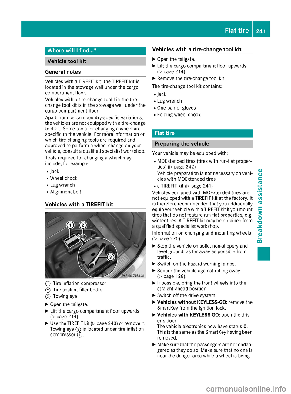
Vehicles with a TIREFIT kit 0043
Tire inflation compressor
0044 Tire sealant filler bottle
0087 Towing eye
X Open the tailgate.
X Lift the cargo compartment floor upwards
(Y page 214).
X Use the TIREFIT kit (Y page 243) or remove it.
Towing eye 0087is located under tire inflation
compressor 0043. Vehicles with a tire-change tool kit X
Open the tailgate.
X Lift the cargo compartment floor upwards
(Y page 214).
X Remove the tire-change tool kit.
The tire-change tool kit contains:
R Jack
R Lug wrench
R One pair of gloves
R Folding wheel chock Flat tire
Preparing the vehicle
Your vehicle may be equipped with:
R MOExtended tires (tires with run-flat proper-
ties) (Y page 242)
Vehicle preparation is not necessary on vehi-
cles with MOExtended tires
R a TIREFIT kit (Y page 241)
Vehicles equipped with MOExtended tires are
not equipped with a TIREFIT kit at the factory. It
is therefore recommended that you additionally
equip your vehicle with a TIREFIT kit if you mount tires that do not feature run-flat properties, e.g.
winter tires. A TIREFIT kit may be obtained from a qualified specialist workshop.
Information on changing and mounting wheels
(Y page 275).
X Stop the vehicle on solid, non-slippery and
level ground, as far away as possible from
traffic.
X Switch on the hazard warning lamps.
X Secure the vehicle against rolling away
(Y page 128).
X If possible, bring the front wheels into the
straight-ahead position.
X Switch off the drive system.
X Vehicles without KEYLESS-GO: remove the
SmartKey from the ignition lock.
X Vehicles with KEYLESS-GO: open the driv-
er's door.
The vehicle electronics now have status 0.
This is the same as the SmartKey having been removed.
X Make sure that the passengers are not endan-
gered as they do so. Make sure that no one is
near the danger area while a wheel is being Flat tire
241Breakdown assistance
Page 245 of 290
TIREFIT kit
Important safety notes TIREFIT is a tire sealant.
You can use TIREFIT to seal punctures of up to
0.16 in (4 mm), particularly those in the tire
tread. You can use TIREFIT at outside tempera-
tures down to 00F84 ‡ (00F820 †). G
WARNING
In the following situations, the tire sealant is
unable to provide sufficient breakdown assis- tance, as it is unable to seal the tire properly:
R there are cuts or punctures in the tire larger
than those mentioned above.
R the wheel rim is damaged.
R you have driven at very low tire pressures or
on a flat tire.
There is a risk of an accident.
Do not drive the vehicle. Contact a qualified
specialist workshop. G
WARNING
The tire sealant is harmful and causes irrita-
tion. It must not come into contact with your
skin, eyes or clothing or be swallowed. Do not inhale TIREFIT fumes. Keep tire sealant away
from children. There is a risk of injury.
If you come into contact with the tire sealant,
observe the following:
R Rinse off the tire sealant from your skin
immediately with water.
R If the tire sealant comes into contact with
your eyes, immediately rinse them thor-
oughly with clean water.
R If tire sealant is swallowed, immediately
rinse your mouth out thoroughly and drink
plenty of water. Do not induce vomiting,
and seek medical attention immediately.
R Immediately change out of clothing which
has come into contact with tire sealant.
R If an allergic reaction occurs, seek medical
attention immediately. !
Residue from the tire sealant may come out
of the filler hose after use. This could cause
stains.
Therefore, place the filler hose in the plastic
bag which contained the TIREFIT kit. H
Environmental note
Have the used tire sealant bottle disposed of
professionally, e.g. at a qualified specialist
workshop.
! Do not operate the tire inflation compressor
for longer than ten minutes at a time without
a break. It may otherwise overheat.
The tire inflation compressor can be operated again once it has cooled down.
Comply with the manufacturer’s safety instruc-
tions on the sticker on the tire inflation com-
pressor.
Using the TIREFIT kit X
Do not remove any foreign objects which have
penetrated the tire, e.g. screws or nails.
X Remove the tire sealant bottle, the accompa-
nying TIREFIT sticker and the tire inflation
compressor from the stowage well under-
neath the cargo compartment floor
(Y page 241).
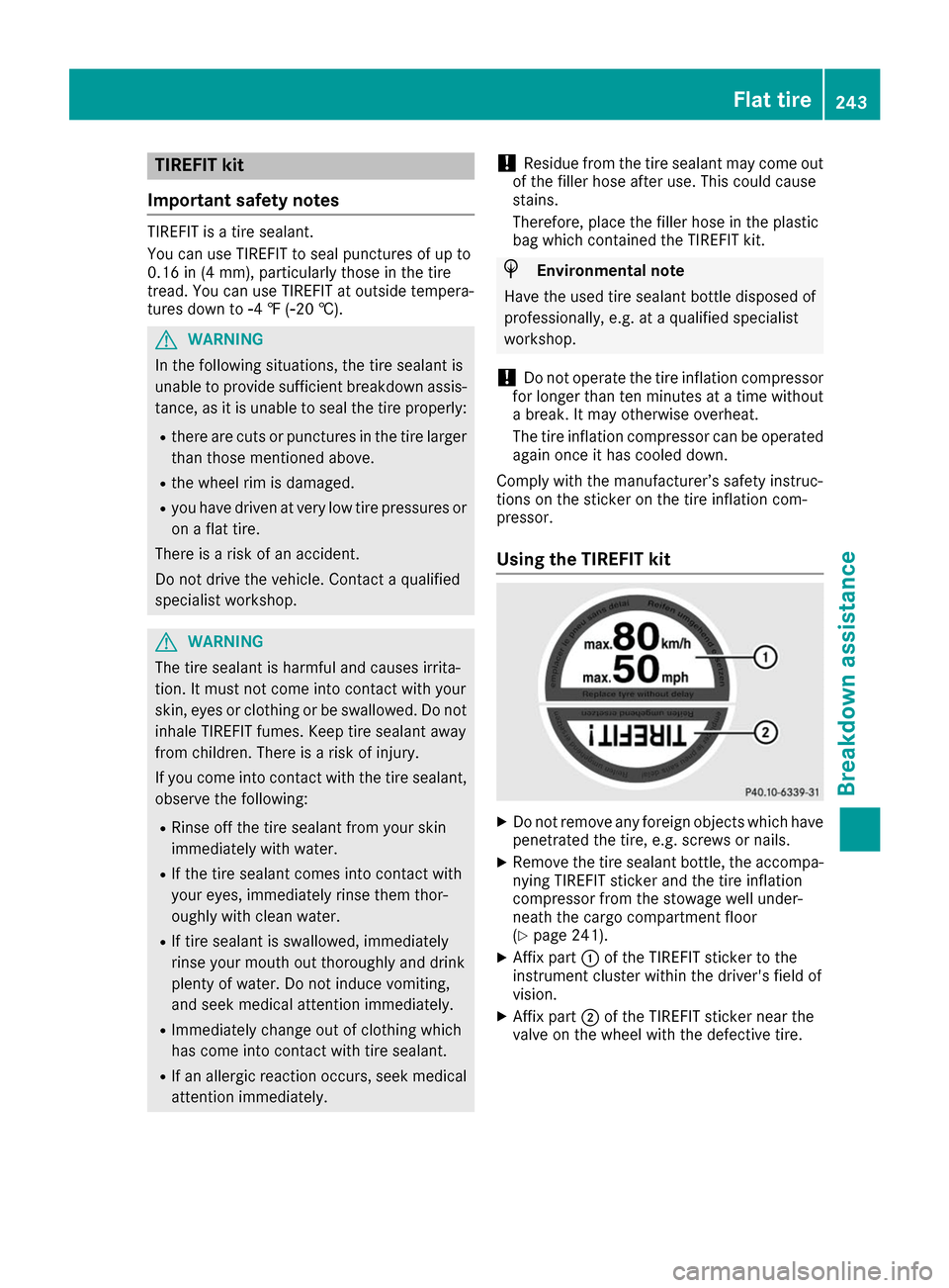
X Affix part 0043of the TIREFIT sticker to the
instrument cluster within the driver's field of
vision.
X Affix part 0044of the TIREFIT sticker near the
valve on the wheel with the defective tire. Flat tire
243Breakdown assistance Z