tow MERCEDES-BENZ B-Class 2017 W246 Repair Manual
[x] Cancel search | Manufacturer: MERCEDES-BENZ, Model Year: 2017, Model line: B-Class, Model: MERCEDES-BENZ B-Class 2017 W246Pages: 290, PDF Size: 19.81 MB
Page 247 of 290
Tire pressure reached
G
WARNING
A tire temporarily sealed with tire sealant
impairs the driving characteristics and is not
suitable for higher speeds. There is a risk of
accident.
You should therefore adapt your driving style
accordingly and drive carefully. Do not exceed the specified maximum speed with a tire that
has been repaired using tire sealant.
The maximum permissible speed for a tire
sealed with tire sealant is 50 mph (80 km/h).
The upper part of the TIREFIT sticker must be
affixed to the instrument cluster in the driver's
field of vision.
If a tire pressure of 200 kPa (2.0 bar/29 psi) has been attained after ten minutes:
X Switch off the tire inflation compressor.
X Unscrew the filler hose from the valve of the
faulty tire.
Note that tire sealant may escape when you
unscrew the filler hose.
X Stow the tire sealant bottle and the tire infla-
tion compressor.
X Pull away immediately.
X Stop after driving for approximately ten
minutes and check the tire pressure with the
tire inflation compressor.
The tire pressure must now be at least
130 kPa (1.3 bar/19 psi). G
WARNING
If the required tire pressure is not reached
after driving for a short period, the tire is too
badly damaged. The tire sealant cannot repair the tire in this instance. Damaged tires and a
tire pressure that is too low can significantly
impair the vehicle's braking and driving char-
acteristics. There is a risk of accident.
Do not continue driving. Contact a qualified
specialist workshop.
i In cases such as the one mentioned above,
contact an authorized Mercedes-Benz Cen-
ter. Or call 1-800-FOR-MERCedes (in the
USA) or 1-800-387-0100 (in Canada). X
Correct the tire pressure if it is still at least
130 kPa (1.3 bar/19 psi). See the Tire and
Loading Information placard on the driver's
side B-pillar or the tire pressure table in the
charge socket flap for values.
X To increase the tire pressure: switch on the
tire inflation compressor. X
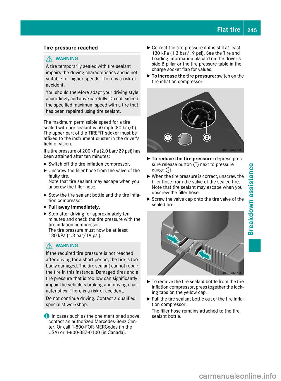
To reduce the tire pressure: depress pres-
sure release button 0043next to pressure
gauge 0044.
X When the tire pressure is correct, unscrew the
filler hose from the valve of the sealed tire.
Note that tire sealant may escape when you
unscrew the filler hose.
X Screw the valve cap onto the tire valve of the
sealed tire. X
To remove the tire sealant bottle from the tire
inflation compressor, press together the lock- ing tabs on the yellow cap.
X Pull the tire sealant bottle out of the tire infla-
tion compressor.
The filler hose remains attached to the tire
sealant bottle. Flat tire
245Breakdown assistance Z
Page 250 of 290
find further information in the separate operat-
ing instructions. Charging the 12‑volt battery
G
WARNING
During charging and jump-starting, explosive
gases can escape from the battery. There is a risk of an explosion.
Particularly avoid fire, open flames, creating
sparks and smoking. Ensure there is sufficient
ventilation while charging and jump-starting.
Do not lean over a battery. G
WARNING
Battery acid is caustic. There is a risk of injury. Avoid contact with skin, eyes or clothing. Do
not inhale any battery gases. Do not lean over
the battery. Keep children away from batter-
ies. Wash away battery acid immediately with
plenty of clean water and seek medical atten- tion. G
WARNING
A discharged battery can freeze at tempera-
tures below freezing point. When jump-start-
ing the vehicle or charging the battery, gases can escape from the battery. There is a risk of
an explosion.
Allow the frozen battery to thaw out before
charging it or jump-starting.
! Only use battery chargers with a maximum
charging voltage of 14.8 V.
! Only
charge the battery using the jump-
starting connection point.
The jump-starting connection point is in the
engine compartment (Y page 249).
X Open the hood.
X Connect the battery charger to the positive
terminal and ground point in the same order
as when connecting the donor battery in the
jump-starting procedure (Y page 249).
If the indicator/warning lamps do not light up in
the instrument cluster at low temperatures, it is very likely that the discharged battery has fro-
zen. In this case you may neither jump-start the vehicle nor charge the battery. The service life of
a thawed-out battery may be shorter. The start-ing characteristics can be impaired, particularly at low temperatures. Have the thawed-out bat-
tery checked at a qualified specialist workshop.
Only charge the installed battery with a battery
charger which has been tested and approved byMercedes-Benz. A battery charger unit specially
adapted for Mercedes-Benz vehicles and tested
and approved by Mercedes-Benz is available as an accessory. It permits the charging of the bat-tery in its installed position. Contact an author-
ized Mercedes-Benz Center for further informa- tion and availability. Read the battery charger's
operating instructions before charging the bat-
tery. High-voltage battery – important
safety notes
G
DANGER
The vehicle's high-voltage electrical system is under high voltage. If you modify components
in the vehicle's high-voltage electrical system
or touch damaged components, you may be
electrocuted. The components in the vehi-
cle's high-voltage electrical system may be
damaged in an accident, although the damage is not visible. There is a risk of fatal injury.
Following an accident, do not touch any high- voltage components and never modify the
vehicle's high-voltage electrical system. Have
the vehicle towed away after an accident and
the vehicle's high-voltage electrical system
checked by a qualified specialist workshop. G
WARNING
In the event of a vehicle fire, the internal pres- sure of the high-voltage battery can exceed a
critical value. In this case flammable gas
escapes through a ventilation valve on the
underbody. The gas can ignite. There is a risk of injury.
Leave the danger zone immediately. Secure
the danger area at a suitable distance, whilst
observing legal requirements. 248
BatteriesBreakdown assistance
Page 253 of 290
X
Switch off the engine of both vehicles.
X Shift the transmission to position P.
X Switch off all electrical consumers.
X Remove battery cover 0043.
X Connect positive terminal 0044on the vehicle with the flat battery to positive terminal 0087of the
donor vehicle using the red jumper cable. Begin with the flat battery.
X Connect negative terminal 0085of the donor vehicle to negative terminal 0083of the vehicle with the
flat battery using the black jumper cable, beginning with donor vehicle's battery 0084.
X Start the engine of the donor vehicle and run it at idling speed.
X Switch on the ignition in the vehicle with the flat battery.
X If the drive system cannot be activated immediately, wait for approximately 60 seconds between
starting attempts.
If the drive system does not start, call a breakdown service.
i Jumper cables and further information regarding jump-starting can be obtained at any qualified
specialist workshop. Towing
Important safety notes
G
WARNING
Functions relevant to safety are restricted or
no longer available if:
R the ignition is switched off
R the brake system or the power steering is
malfunctioning
R there is a malfunction in the power supply
or the vehicle's electrical system
If your vehicle is being towed, much more
force may be necessary to steer or brake.
There is a risk of an accident.
In such cases, use a tow bar. Before towing,
make sure that the steering moves freely. G
WARNING
You can no longer steer the vehicle if the
steering wheel lock has been engaged. There is a risk of an accident.
Always switch off the ignition when towing the
vehicle with a tow cable or a tow bar. G
WARNING
When towing or tow-starting another vehicle
and its weight is greater than the permissible gross weight of your vehicle, the:
R the towing eye could detach itself
R the vehicle/trailer combination could roll-
over.
There is a risk of an accident.
When towing or tow-starting another vehicle,
its weight should not be greater than the per- missible gross weight of your vehicle.
Details on the permissible gross vehicle weight
of your vehicle can be found on the vehicle iden-
tification plate (Y page 282).
! When Active Brake Assist or the HOLD func-
tion is activated, the vehicle brakes automat- ically in certain situations. To avoid damage to the vehicle, deactivate these systems in the
following or similar situations:
R when towing the vehicle
R in the car wash
! Make sure that the electric parking brake is
released. If the electric parking brake is faulty,
visit a qualified specialist workshop.
Mercedes-Benz recommends that you use an authorized Mercedes-Benz Center for this
purpose. Towing
251Breakdown assistance Z
Page 254 of 290
!
Only secure the tow rope or tow bar at the
towing eyes. Otherwise, the vehicle could be
damaged.
! Observe the following points when towing
with a tow rope:
R Secure the tow rope on the same side on
both vehicles.
R Ensure that the tow cable is not longer than
legally permitted. Mark the tow cable in the
middle, e.g. with a white cloth (30 x 30 cm). This will make other road users aware that
the vehicle is being towed.
R Only secure the tow cable to the towing
eye.
R Observe the brake lamps of the towing
vehicle while driving. Always maintain a dis-
tance so that the tow rope does not sag.
R Do not use steel cables or chains to tow
your vehicle. You could otherwise damage
the vehicle.
! Do not use the towing eyes for recovery pur-
poses as this could damage the vehicle. If in
doubt, recover the vehicle with a crane.
! When towing, pull away slowly and
smoothly. If the tractive power is too high, the vehicles could be damaged.
! The vehicle can be towed a maximum of
30 miles (50km). The towing speed of 30 mph
(50km/h) must not be exceeded.
If the vehicle has to be towed more than
30 miles (50km), the front axle must be raised
or the entire vehicle raised and transported.
! Do not tow with sling-type equipment. This
could damage the vehicle.
! To tow vehicles with KEYLESS-GO, use the
SmartKey instead of the Start/Stop button.
The transmission may otherwise shift to posi- tion Pwhen you open the driver's or front-
passenger door, which could damage the
transmission.
Observe the legal requirements for the relevant countries when towing away.
Make sure that no charging cable is plugged in.
The parking lock cannot be released if a charg-
ing cable is plugged in.
It is better to have the vehicle transported than
to have it towed away. If the vehicle can no longer be driven because of
an accident or breakdown, you have the follow-
ing options:
R transporting the vehicle
As a rule, you should have the vehicle trans-
ported.
R towing the vehicle with a tow rope or tow bar
Only tow the vehicle in exceptional cases.
Observe the following notes.
The vehicle may not be towed and must always be transported if:
R the multifunction display is not working
R one of more of the following warning lamps is
lit up:
- Drive system
- 12 V battery
R one or both of the following display messages
have appeared:
- Stop Switch Engine Off
Stop Switch Engine Off
- Service Required Do Not Shift Service Required Do Not Shift
Gears Visit Dealer Gears Visit Dealer
R you have to tow the vehicle over a longer dis-
tance than 30 miles (50 km).
The battery must be connected and charged.
Otherwise, you:
R cannot turn the SmartKey to position 2in the
ignition lock
R cannot release the electric parking brake
R cannot move the transmission to position N
The function of the electric parking brake and
the parking lock is dependent on the on-board
voltage.
If the on-board voltage is low or if there is a sys- tem malfunction:
R the electric parking brake may not be applied
in certain circumstances, or
R the transmission may not be shifted to P
Switch off non-essential consumers, e.g. the
radio.
Disarm the automatic locking feature before the
vehicle is towed (Y page 166). You could other-
wise be locked out when pushing or towing the
vehicle. 252
TowingBreakdown assistance
Page 255 of 290
Installing/removing the towing eye
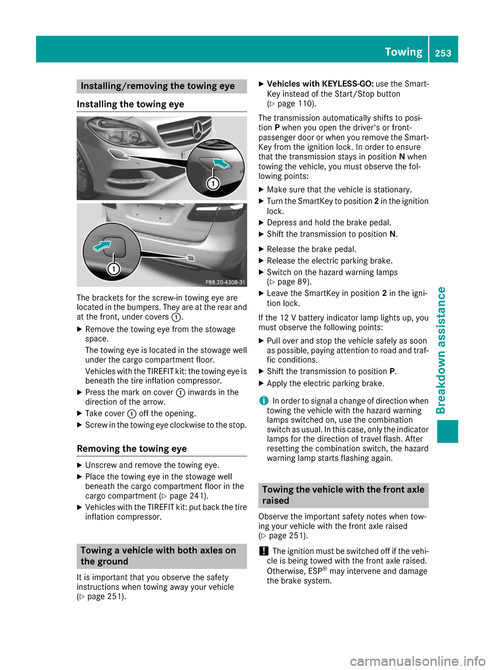
Installing the towing eye The brackets for the screw-in towing eye are
located in the bumpers. They are at the rear and
at the front, under covers 0043.
X Remove the towing eye from the stowage
space.
The towing eye is located in the stowage well
under the cargo compartment floor.
Vehicles with the TIREFIT kit: the towing eye is
beneath the tire inflation compressor.
X Press the mark on cover 0043inwards in the
direction of the arrow.
X Take cover 0043off the opening.
X Screw in the towing eye clockwise to the stop.
Removing the towing eye X
Unscrew and remove the towing eye.
X Place the towing eye in the stowage well
beneath the cargo compartment floor in the
cargo compartment (Y page 241).
X Vehicles with the TIREFIT kit: put back the tire
inflation compressor. Towing a vehicle with both axles on
the ground
It is important that you observe the safety
instructions when towing away your vehicle
(Y page 251). X
Vehicles with KEYLESS-GO: use the Smart-
Key instead of the Start/Stop button
(Y page 110).
The transmission automatically shifts to posi-
tion Pwhen you open the driver's or front-
passenger door or when you remove the Smart-
Key from the ignition lock. In order to ensure
that the transmission stays in position Nwhen
towing the vehicle, you must observe the fol-
lowing points:
X Make sure that the vehicle is stationary.
X Turn the SmartKey to position 2in the ignition
lock.
X Depress and hold the brake pedal.
X Shift the transmission to position N.
X Release the brake pedal.
X Release the electric parking brake.
X Switch on the hazard warning lamps
(Y page 89).
X Leave the SmartKey in position 2in the igni-
tion lock.
If the 12 V battery indicator lamp lights up, you must observe the following points:
X Pull over and stop the vehicle safely as soon
as possible, paying attention to road and traf-
fic conditions.
X Shift the transmission to position P.
X Apply the electric parking brake.
i In order to signal a change of direction when
towing the vehicle with the hazard warning
lamps switched on, use the combination
switch as usual. In this case, only the indicator lamps for the direction of travel flash. After
resetting the combination switch, the hazard
warning lamp starts flashing again. Towing the vehicle with the front axle
raised
Observe the important safety notes when tow-
ing your vehicle with the front axle raised
(Y page 251).
! The ignition must be switched off if the vehi-
cle is being towed with the front axle raised.
Otherwise, ESP ®
may intervene and damage
the brake system. Towing
253Breakdown assistance Z
Page 256 of 290
X
Vehicles with KEYLESS-GO: use the Smart-
Key instead of the Start/Stop button
(Y page 110).
X Make sure that the vehicle is stationary.
X Turn the SmartKey to position 2in the ignition
lock.
X When the vehicle is stationary, depress the
brake pedal and keep it depressed.
X Shift the transmission to position P.
X Release the brake pedal.
X Release the electric parking brake.
X Switch off the automatic locking
(Y page 166).
X Switch on the hazard warning lamps
(Y page 89).
X Turn the SmartKey in the ignition lock to posi-
tion 0and leave the SmartKey in the ignition
lock. Towing the vehicle with the rear axle
raised
When towing your vehicle with the rear axle
raised, it is important that you observe the
safety instructions (Y page 251).
! The ignition must be switched off if you are
towing the vehicle with the rear axle raised.
Intervention by ESP ®
could otherwise dam-
age the brake system.
The transmission automatically shifts to posi-
tion Pwhen you open the driver's or front-
passenger door or when you remove the Smart-
Key from the ignition lock. In order to ensure
that the transmission stays in position Nwhen
towing the vehicle, you must observe the fol-
lowing points:
X Vehicles with KEYLESS-GO: use the Smart-
Key instead of the Start/Stop button
(Y page 110).
X Make sure that the vehicle is stationary.
X Turn the SmartKey to position 2in the ignition
lock.
X Depress and hold the brake pedal.
X Shift the transmission to position N.
X Release the brake pedal.
X Apply the electric parking brake.
X Switch off the automatic locking
(Y page 166). X
Bring the front wheels into the straight-ahead
position.
X Switch on the hazard warning lamps
(Y page 89).
X Turn the SmartKey in the ignition lock to posi-
tion 0and leave the SmartKey in the ignition
lock. Transporting the vehicle
All vehicles !
You may only secure the vehicle by the
wheels, not by parts of the vehicle such as
axle or steering components. Otherwise, the
vehicle could be damaged.
X Turn the SmartKey to position 2in the ignition
lock (Y page 109).
X Shift the transmission to position N.
As soon as the vehicle has been loaded: X Prevent the vehicle from rolling away by
applying the electric parking brake.
X Shift the transmission to position P.
X Turn the SmartKey to position 0in the ignition
lock and remove it.
X Secure the vehicle.
The towing eye can be used to pull the vehicle
onto a trailer or transporter for transporting pur- poses. Fuses
Important safety notes
G
WARNING
If you manipulate or bridge a faulty fuse or if
you replace it with a fuse with a higher amper- age, the electric cables could be overloaded.
This could result in a fire. There is a risk of an
accident and injury.
Always replace faulty fuses with the specified
new fuses having the correct amperage.
! Only use fuses that have been approved for
Mercedes-Benz vehicles and which have the
correct fuse rating for the system concerned.
Only use fuses marked with an "S". Other- 254
FusesBreakdown assistance
Page 281 of 290
X
Clean the wheel and wheel hub contact sur-
faces.
X Place the new wheel on the wheel hub and
push it on.
X Tighten the wheel bolts until they are finger-
tight.
Lowering the vehicle G
WARNING
The wheels could work loose if the wheel nuts and bolts are not tightened to the specified
tightening torque. There is a risk of accident.
Have the tightening torque immediately
checked at a qualified specialist workshop
after a wheel is changed.
X Place the ratchet wrench onto the hexagon
nut of the jack so that the letters ABare visi-
ble.
X Turn the ratchet wrench until the vehicle is
once again standing firmly on the ground.
X Place the jack to one side. X
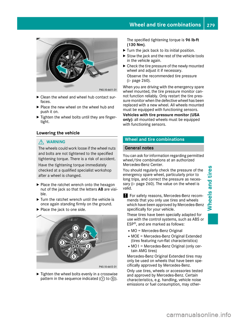
Tighten the wheel bolts evenly in a crosswise
pattern in the sequence indicated (0043 to0083). The specified tightening torque is
96 lb-ft
(130 Nm) .
X Turn the jack back to its initial position.
X Stow the jack and the rest of the vehicle tools
in the vehicle again.
X Check the tire pressure of the newly mounted
wheel and adjust it if necessary.
Observe the recommended tire pressure
(Y page 260).
When you are driving with the emergency spare
wheel mounted, the tire pressure monitor can-
not function reliably. Only restart the tire pres-
sure monitor when the defective wheel has been
replaced with a new wheel. All wheels mounted
must be equipped with functioning sensors.
Vehicles with tire pressure monitor (USA
only): all mounted wheels must be equipped
with functioning sensors. Wheel and tire combinations
General notes
You can ask for information regarding permitted wheel/tire combinations at an authorized
Mercedes-Benz Center.
You should regularly check the pressure of the
emergency spare wheel, particularly prior to
long trips, and correct the pressure as neces-
sary (Y page 260). The value on the wheel is
valid.
! For safety reasons, Mercedes-Benz recom-
mends that you only use tires and wheels
which have been approved by Mercedes-Benz specifically for your vehicle.
These tires have been specially adapted for
use with the control systems, such as ABS or
ESP ®
, and are marked as follows:
R MO = Mercedes-Benz Original
R MOE = Mercedes-Benz Original Extended
(tires featuring run-flat characteristics)
R MO1 = Mercedes-Benz Original (only cer-
tain AMG tires)
Mercedes-Benz Original Extended tires may
only be used on wheels that have been spe-
cifically approved by Mercedes-Benz.
Only use tires, wheels or accessories tested
and approved by Mercedes-Benz. Certain
characteristics, e.g. handling, vehicle noise
emissions or fuel consumption, may other- Wheel and tire combinations
279Wheels and tires Z