egr MERCEDES-BENZ B-Class 2017 W246 Owner's Manual
[x] Cancel search | Manufacturer: MERCEDES-BENZ, Model Year: 2017, Model line: B-Class, Model: MERCEDES-BENZ B-Class 2017 W246Pages: 290, PDF Size: 19.81 MB
Page 3 of 290
Welcome to the world of Mercedes-Benz
We urge you to read this Operator's Manual
carefully and familiarize yourself with the vehi-
cle before driving. For your own safety and a
longer vehicle life, follow the instructions and
warning notices in this Operator's Manual.
Ignoring them could result in damage to the
vehicle or personal injury to you or others.
Vehicle damage caused by failure to follow
instructions is not covered by the Mercedes-
Benz Limited Warranty.
The equipment or product designation of your
vehicle may vary depending on:
R Model
R Order
R Country specification
R Availability
Mercedes-Benz therefore reserves the right to
introduce changes in the following areas:
R Design
R Equipment
R Technical features
The equipment in your vehicle may therefore
differ from that shown in the descriptions and
illustrations.
The following are integral components of the
vehicle:
R Printed Operator's Manual
R Maintenance Booklet
R Equipment-dependent supplements
Keep these documents in the vehicle at all
times. If you sell the vehicle, always pass all
documents on to the new owner.
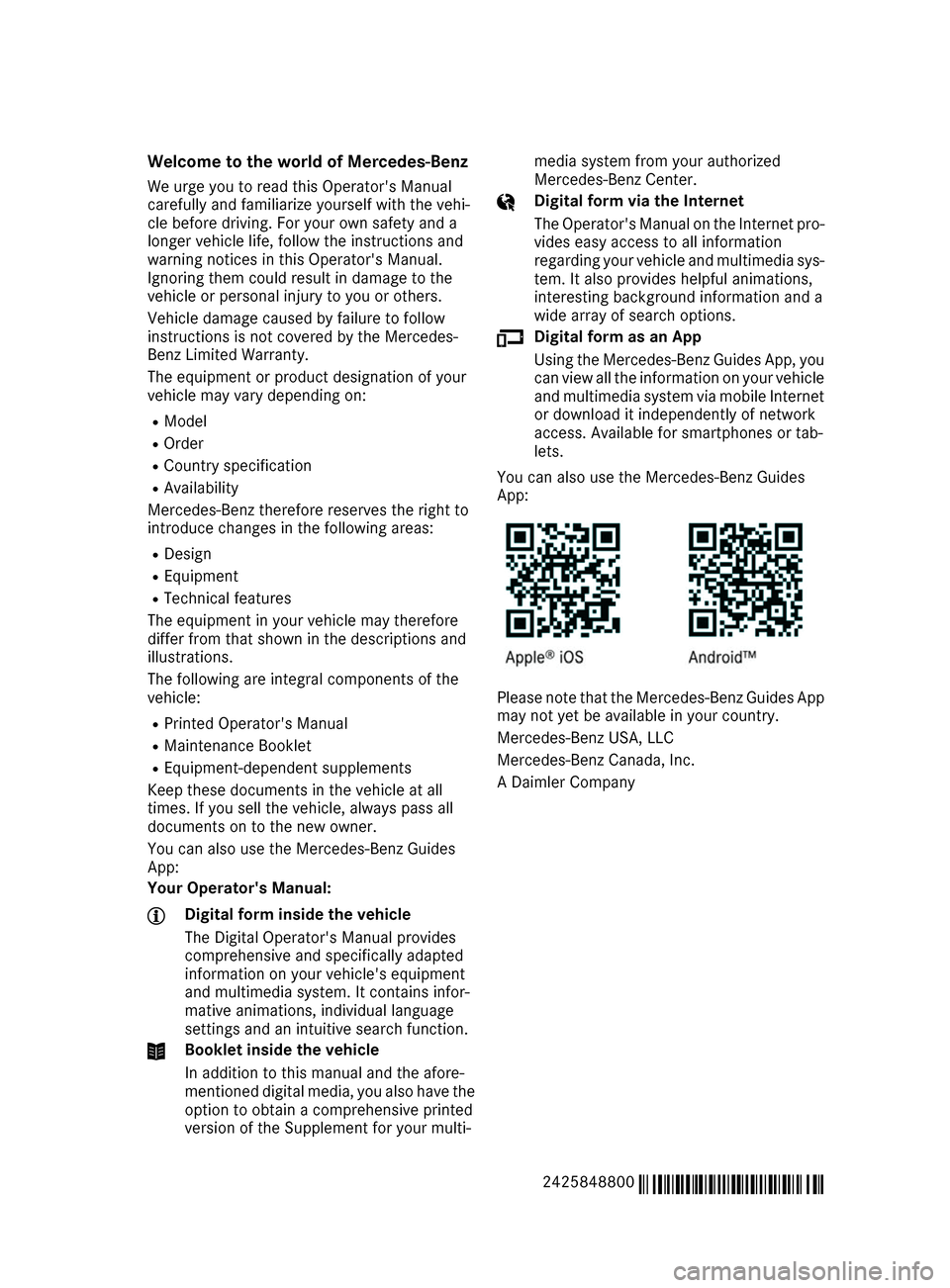
You can also use the Mercedes-Benz Guides
App:
Your Operator's Manual: Digital form inside the vehicle
The Digital Operator's Manual provides
comprehensive and specifically adapted
information on your vehicle's equipment
and multimedia system. It contains infor-
mative animations, individual language
settings and an intuitive search function. Booklet inside the vehicle
In addition to this manual and the afore-
mentioned digital media, you also have the option to obtain a comprehensive printed
version of the Supplement for your multi- media system from your authorized
Mercedes-Benz Center. Digital form via the Internet
The Operator's Manual on the Internet pro-
vides easy access to all information
regarding your vehicle and multimedia sys- tem. It also provides helpful animations,
interesting background information and a
wide array of search options. Digital form as an App
Using the Mercedes-Benz Guides App, you
can view all the information on your vehicle and multimedia system via mobile Internetor download it independently of network
access. Available for smartphones or tab-
lets.
You can also use the Mercedes-Benz Guides
App: Please note that the Mercedes-Benz Guides App
may not yet be available in your country.
Mercedes-Benz USA, LLC
Mercedes-Benz Canada, Inc.
A Daimler Company
2425848800 É2425848800gËÍ
Page 47 of 290
Side impact air bags
G
WARNING
Unsuitable seat covers can obstruct or pre-
vent deployment of the air bags integrated
into the seats. Consequently, the air bags
cannot protect vehicle occupants as they are designed to do. In addition, the operation of
the occupant classification system (OCS)
could be adversely affected. This poses an
increased risk of injury or even fatal injury.
You should only use seat covers that have
been approved for the respective seat by
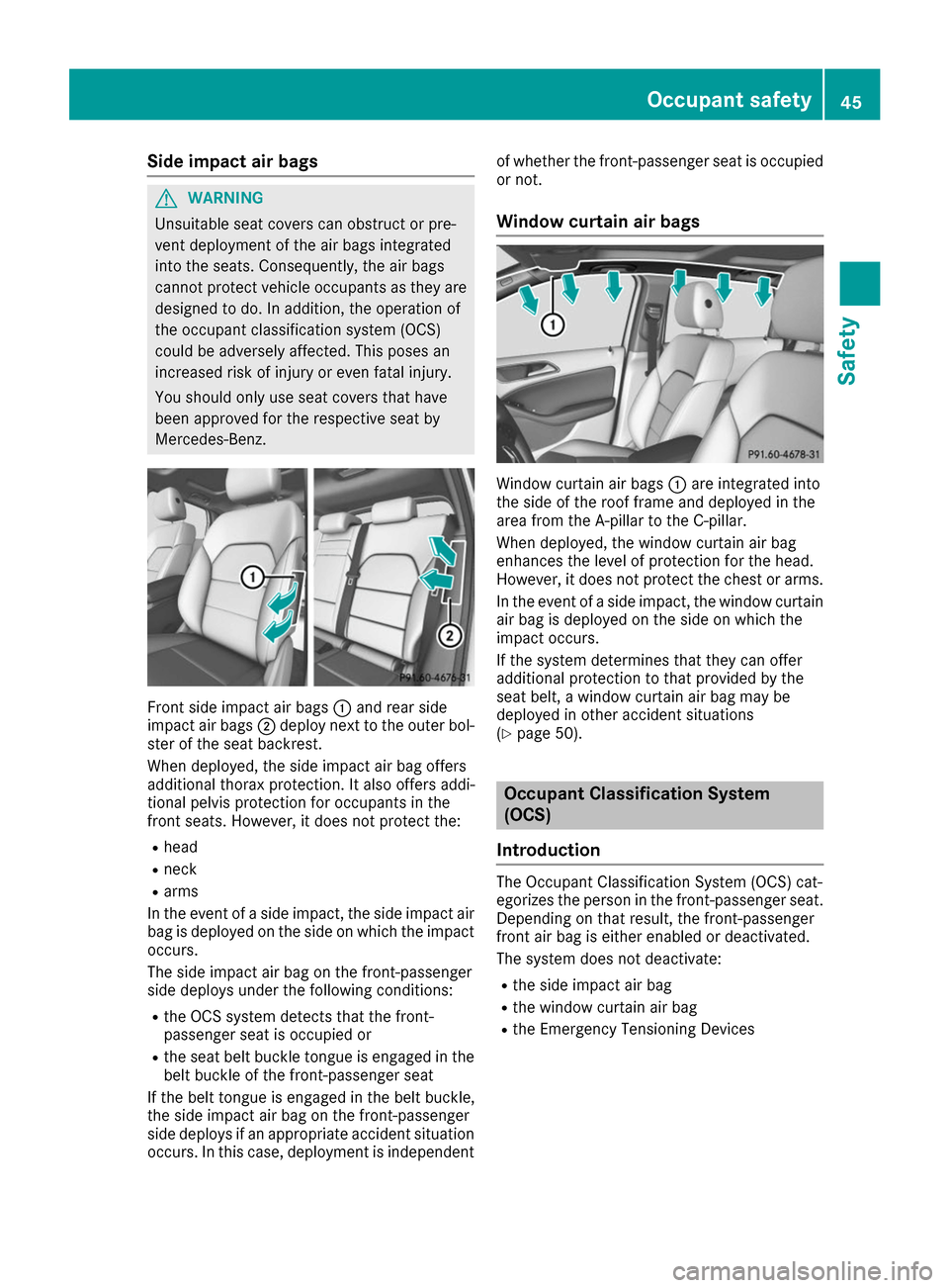
Mercedes-Benz. Front side impact air bags
0043and rear side
impact air bags 0044deploy next to the outer bol-
ster of the seat backrest.
When deployed, the side impact air bag offers
additional thorax protection. It also offers addi-
tional pelvis protection for occupants in the
front seats. However, it does not protect the:
R head
R neck
R arms
In the event of a side impact, the side impact air bag is deployed on the side on which the impactoccurs.
The side impact air bag on the front-passenger
side deploys under the following conditions:
R the OCS system detects that the front-
passenger seat is occupied or
R the seat belt buckle tongue is engaged in the
belt buckle of the front-passenger seat
If the belt tongue is engaged in the belt buckle,
the side impact air bag on the front-passenger
side deploys if an appropriate accident situation
occurs. In this case, deployment is independent of whether the front-passenger seat is occupied
or not.
Window curtain air bags Window curtain air bags
0043are integrated into
the side of the roof frame and deployed in the
area from the A-pillar to the C-pillar.
When deployed, the window curtain air bag
enhances the level of protection for the head.
However, it does not protect the chest or arms.
In the event of a side impact, the window curtain
air bag is deployed on the side on which the
impact occurs.
If the system determines that they can offer
additional protection to that provided by the
seat belt, a window curtain air bag may be
deployed in other accident situations
(Y page 50). Occupant Classification System
(OCS)
Introduction The Occupant Classification System (OCS) cat-
egorizes the person in the front-passenger seat.
Depending on that result, the front-passenger
front air bag is either enabled or deactivated.
The system does not deactivate:
R the side impact air bag
R the window curtain air bag
R the Emergency Tensioning Devices Occupant safety
45Safety Z
Page 57 of 290
LATCH-type (ISOFIX) child seat secur-
ing system G
WARNING
LATCH-type (ISOFIX) child restraint systems
do not offer sufficient protective effect for
children whose weight is greater than 48 lbs
(22 kg) who are secured using the safety belt integrated in the child restraint system. In the
event of an accident, a child might not be
restrained correctly. This poses an increased
risk of injury or even fatal injury.
If the child weighs more than 48 lbs (22 kg),
only use LATCH-type (ISOFIX) child restraint
systems with which the child is also secured
with the vehicle seat belt. Also secure the
child restraint system with the Top Tether
belt, if available.
Always comply with the manufacturer's instal-
lation and operating instructions for the child
restraint system used.
Before every trip, make sure that the LATCH-
type (ISOFIX) child restraint system is engaged
correctly in both LATCH-type (ISOFIX) securing
rings
! When installing the child restraint system,
make sure that the seat belt for the middle
seat does not get trapped. The seat belt could
otherwise be damaged. X
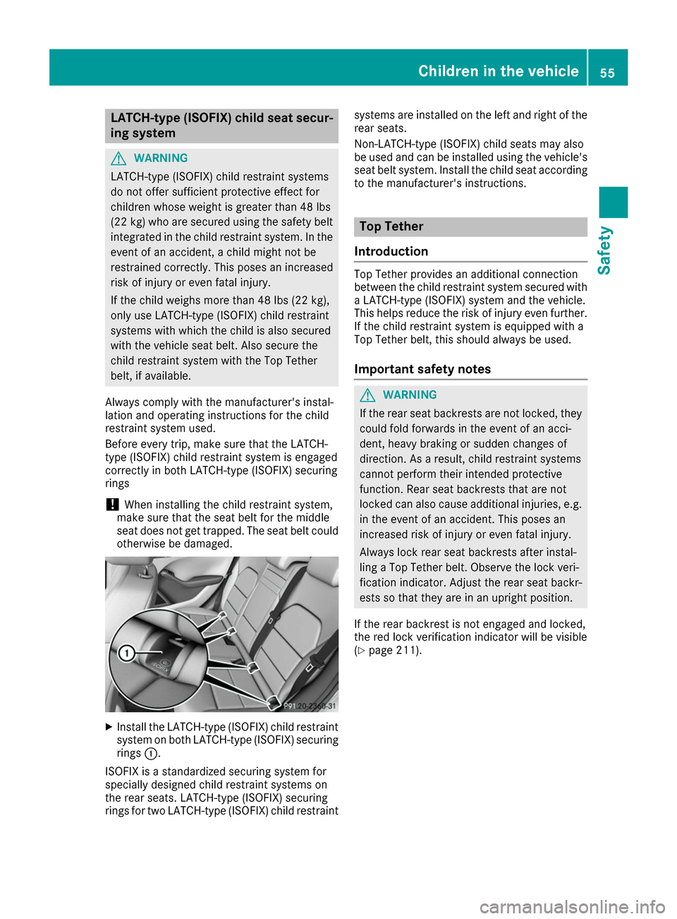
Install the LATCH-type (ISOFIX) child restraint
system on both LATCH-type (ISOFIX) securing
rings 0043.
ISOFIX is a standardized securing system for
specially designed child restraint systems on
the rear seats. LATCH-type (ISOFIX) securing
rings for two LATCH-type (ISOFIX) child restraint systems are installed on the left and right of the
rear seats.
Non-LATCH-type (ISOFIX) child seats may also
be used and can be installed using the vehicle's seat belt system. Install the child seat according
to the manufacturer's instructions. Top Tether
Introduction Top Tether provides an additional connection
between the child restraint system secured with
a LATCH-type (ISOFIX) system and the vehicle.
This helps reduce the risk of injury even further.
If the child restraint system is equipped with a
Top Tether belt, this should always be used.
Important safety notes G
WARNING
If the rear seat backrests are not locked, they
could fold forwards in the event of an acci-
dent, heavy braking or sudden changes of
direction. As a result, child restraint systems
cannot perform their intended protective
function. Rear seat backrests that are not
locked can also cause additional injuries, e.g. in the event of an accident. This poses an
increased risk of injury or even fatal injury.
Always lock rear seat backrests after instal-
ling a Top Tether belt. Observe the lock veri-
fication indicator. Adjust the rear seat backr-
ests so that they are in an upright position.
If the rear backrest is not engaged and locked,
the red lock verification indicator will be visible
(Y page 211). Children in the vehicle
55Safety Z
Page 63 of 290
Function
Starting at a speed of approximately 4 mph
(7 km/h), the distance warning function warns
you if you rapidly approach a vehicle in front. An
intermittent warning tone will then sound, and
the 00BA distance warning lamp will light up in
the instrument cluster.
X Brake immediately in order to increase the
distance from the vehicle in front.
or X Take evasive action, provided it is safe to do
so.
Due to the nature of the system, particularly
complicated but non-critical driving conditions
may also cause the system to display a warning.
With the help of the radar sensor system, the
distance warning function can detect obstacles
that are in the path of your vehicle for an exten-
ded period of time.
Up to a speed of approximately 44 mph
(70 km/ h), the distance warning function can
also react to stationary obstacles, such as stop-
ped or parked vehicles.
Autonomous braking function If the driver does not react to the distance warn-
ing signal in a critical situation, Active Brake
Assist can assist the driver with the autonomous braking function.
The autonomous braking function:
R gives the driver more time to react to critical
driving situations
R can help the driver to avoid an accident or
R reduces the effects of an accident
The autonomous braking function is available in
the following speed ranges:
R 4 - 65 mph (7 - 105 km/ h)for moving objects
R 4 - 31 mph (7 - 50 km/h) for stationary
objects
Due to the nature of the system, particularly
complicated but non-critical driving conditions
may also cause the Autonomous Braking Func-
tion to intervene. Braking assistance appropriate to the
situation General information
i Observe the "Important safety notes" sec-
tion (Y page 58).
With the help of the radar sensor system, Adap- tive Brake Assist can detect obstacles that are in
the path of your vehicle for an extended period
of time.
If Adaptive Brake Assist detects a risk of colli-
sion with the vehicle in front, it calculates the
brake pressure necessary to avoid a collision. If
you apply the brakes forcefully, the braking
assistance adapts to the situation and automat-
ically increases the brake pressure to a degree
appropriate to the traffic situation.
Braking assistance appropriate to the situation
provides braking assistance in hazardous situa- tions at speeds above 4 mph (7 km/h). It uses
radar sensor technology to assess the traffic
situation.
Situation-dependent braking assistance is capa-
ble of reacting to moving objects that have
already been recognized as such at least once
over the period of observation, up to vehicle
speeds of around 155 mph (250 km/h).
Braking assistance appropriate to the situation
can also detect stationary objects, up to vehicle speeds of around 44 mph 70 km/h.
X Keep the brake pedal depressed until the
emergency braking situation is over.
ABS prevents the wheels from locking.
The brakes will work normally again if: R you release the brake pedal.
R there is no longer any danger of a collision.
R no obstacle is detected in front of your vehi-
cle.
Braking assistance appropriate to the situation
is then deactivated.
Important safety notes i Observe the "Important safety notes" sec-
tion for driving safety systems (Y page 58). G
WARNING
Adaptive Brake Assist does not react:
R to people or animals
R to oncoming vehicles Driving safety systems
61Safety
Z
Page 101 of 290
Overview of climate control systems
General notes
Observe the settings recommended on the fol-
lowing pages. The windows could otherwise fog up.
To prevent the windows from fogging up:
R switch off climate control only briefly
R switch on air-recirculation mode only briefly
R switch on the cooling with air dehumidifica-
tion function
R switch on the defrost windshield function
briefly, if required
The dual-zone automatic climate control regu-
lates the temperature and the humidity in the
vehicle interior and filters undesirable substan-
ces out of the air.
Dual-zone automatic climate control is only
operational when the vehicle is ready to drive.
Optimum operation is only achieved with the
side windows closed.
Always keep the ventilation flaps behind the
side paneling in the cargo compartment clear.
Otherwise the vehicle will not be ventilated cor- rectly. i
Ventilate the vehicle for a brief period during
warm weather, e.g. using the convenience
opening feature (Y page 76). This will speed
up the cooling process and the desired inte-
rior temperature will be reached more
quickly.
i The integrated filter filters out most parti-
cles of dust and soot and completely filters
out pollen. It also reduces gaseous pollutants and odors. A clogged filter reduces the
amount of air supplied to the vehicle interior.
For this reason, you should always observe
the interval for replacing the filter, which is
specified in the Maintenance Booklet. As it
depends on environmental conditions, e.g.
heavy air pollution, the interval may be
shorter than stated in the Maintenance Book-
let.
i It is possible that under certain circumstan-
ces the residual heat function may be activa-
ted automatically an hour after the SmartKey has been removed in order to dry the auto-
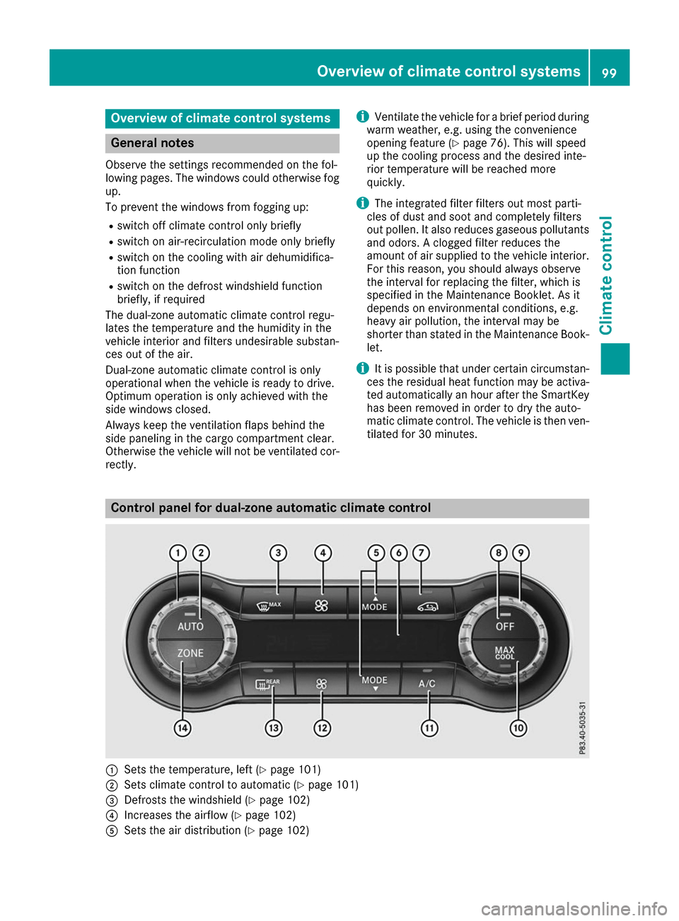
matic climate control. The vehicle is then ven-tilated for 30 minutes. Control panel for dual-zone automatic climate control
0043
Sets the temperature, left (Y page 101)
0044 Sets climate control to automatic (Y page 101)
0087 Defrosts the windshield (Y page 102)
0085 Increases the airflow (Y page 102)
0083 Sets the air distribution (Y page 102) Overview of climate control systems
99Climate control
Page 111 of 290
SmartKey positions
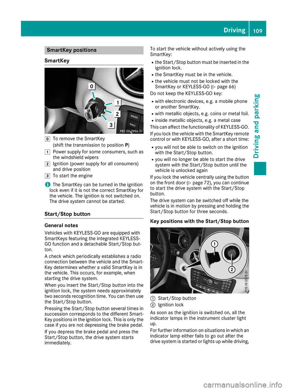
SmartKey 005A
To remove the SmartKey
(shift the transmission to position P)
0047 Power supply for some consumers, such as
the windshield wipers
0048 Ignition (power supply for all consumers)
and drive position
0049 To start the engine
i The SmartKey can be turned in the ignition
lock even if it is not the correct SmartKey for
the vehicle. The ignition is not switched on.
The drive system cannot be started.
Start/Stop button General notes
Vehicles with KEYLESS-GO are equipped with
SmartKeys featuring the integrated KEYLESS-
GO function and a detachable Start/Stop but-
ton.
A check which periodically establishes a radio
connection between the vehicle and the Smart-
Key determines whether a valid SmartKey is in
the vehicle. This occurs, for example, when
starting the drive system.
When you insert the Start/Stop button into the
ignition lock, the system needs approximately
two seconds recognition time. You can then use the Start/Stop button.
Pressing the Start/Stop button several times in
succession corresponds to the different Smart- Key positions in the ignition lock. This is only the
case if you are not depressing the brake pedal.
If you depress the brake pedal and press the
Start/Stop button, the drive system starts
immediately. To start the vehicle without actively using the
SmartKey:
R
the Start/Stop button must be inserted in the
ignition lock.
R the SmartKey must be in the vehicle.
R the vehicle must not be locked with the
SmartKey or KEYLESS-GO (Y page 66)
Do not keep the KEYLESS-GO key:
R with electronic devices, e.g. a mobile phone
or another SmartKey.
R with metallic objects, e.g. coins or metal foil.
R inside metallic objects, e.g. a metal case
This can affect the functionality of KEYLESS-GO.
If you lock the vehicle with the SmartKey remote
control or with KEYLESS-GO, after a short time:
R you will not be able to switch on the ignition
with the Start/Stop button.
R you will no longer be able to start the drive
system with the Start/Stop button until the
vehicle is unlocked again
If you lock the vehicle centrally using the button
on the front door (Y page 72), you can continue
to start the drive system with the Start/Stop
button.
The drive system can be switched off while the
vehicle is in motion by pressing and holding the Start/Stop button for three seconds.
Key positions with the Start/Stop button 0043
Start/Stop button
0044 Ignition lock
As soon as the ignition is switched on, all the
indicator lamps in the instrument cluster light
up.
For further information on situations in which an indicator lamp either fails to go out after the
drive system is started or lights up while driving, Driving
109Driving and parking Z
Page 129 of 290
Problem
Possible causes/consequences and
0050
0050Solutions The charging cable con-
nector cannot be
removed from the vehi-
cle socket. The snap fastener on the charging cable connector is locked.
X Press and hold the button on the charging cable connector. The
snap fastener on the vehicle socket is unlocked.
X Remove the charging cable connector from the vehicle socket. The snap fastener on the charging cable connector is blocked.
X Press and hold the button on the charging cable connector.
X Try to remove the blockage. Online access to the vehicle
General notes G
WARNING
If you operate information systems and com-
munication equipment integrated in the vehi- cle while driving, you will be distracted from
traffic conditions. You could also lose control of the vehicle. There is a risk of an accident.
Only operate the equipment when the traffic
situation permits. If you are not sure that this
is possible, park the vehicle paying attention
to traffic conditions and operate the equip-
ment when the vehicle is stationary.
You must observe the legal requirements for the country in which you are currently driving whenoperating integrated information systems and
communications equipment.
Only use information systems and communica-
tions devices if this is permitted while driving
and if the traffic situation permits. You may oth-
erwise be distracted from the traffic conditions,
cause an accident and injure yourself and oth-
ers.
From the "My Mercedes Electric - Vehicle Home-
page", you can call up remote query and remote
configuration functions for your vehicle. This is
possible from an Internet-enabled computer, as well as many modern smartphones.
You can access the "Vehicle Homepage" via
your web browser.
Please call the Mercedes-Benz Customer Assis-
tance Center (USA) at the hotline number
1-800-FOR-MERCedes (1-800-367-6372) to
obtain the relevant Internet address. In order to use the "Vehicle Homepage", you
must agree to the applicable terms of use.
The contractual periods of mbrace apply to the
"Vehicle Homepage". To use the "Vehicle Home-
page", you require an activated mbrace access
and a separate activation or registration for the "Vehicle Homepage".
Further information about the supported end
devices, available languages and contractual
periods is available at an authorized Mercedes-
Benz Center.
In order to call up the "Vehicle Homepage", the
vehicle must be connected to the Internet.
This is possible via the radio module
(Y page 128).
Notes on data protection Bear in mind that the "Vehicle Homepage" offers
access to your data. Therefore, look after the
vehicle verification code (VVC) and your user
details carefully.
The vehicle verification code (VVC) is required
when you register for the first time on the "Vehi- cle Homepage". Using this code, the vehicle andthe user access are linked to each other on the
"Vehicle Homepage", enabling the intended
usage. You can obtain further information from
an authorized Mercedes-Benz Center.
Prevent unauthorized persons from access- ing this data.
Every person who has access to the informationstated can use the functions on the "Vehicle
Homepage".
R If you sell your vehicle, you are obliged to
delete the vehicle from your personal area on
the "Vehicle Homepage". Additionally, you High-voltage battery
127Driving and parking Z
Page 154 of 290
Important safety notes
G
WARNING
If you operate information systems and com-
munication equipment integrated in the vehi- cle while driving, you will be distracted from
traffic conditions. You could also lose control of the vehicle. There is a risk of an accident.
Only operate the equipment when the traffic
situation permits. If you are not sure that this
is possible, park the vehicle paying attention
to traffic conditions and operate the equip-
ment when the vehicle is stationary.
You must observe the legal requirements for the country in which you are currently driving whenoperating the on-board computer. G
WARNING
If the instrument cluster has failed or mal-
functioned, you may not recognize function
restrictions in systems relevant to safety. The operating safety of your vehicle may be
impaired. There is a risk of an accident.
Drive on carefully. Have the vehicle checked
at a qualified specialist workshop immedi-
ately.
The on-board computer only shows messages or
warnings from certain systems in the multifunc- tion display. You should therefore make sure
your vehicle is operating safely at all times.
If the operating safety of your vehicle is
impaired, pull over as soon as it is safe to do so. Contact a qualified specialist workshop.
For an overview, see the instrument panel illus-
tration (Y page 32). Displays and operation
Instrument cluster lighting
The light sensor in the instrument cluster auto-
matically controls the brightness of the multi-
function display. In daylight, the displays in the
instrument cluster are not illuminated.
The lighting in the instrument cluster, in the dis-
plays and the controls in the vehicle interior can be adjusted using the brightness control knob. The brightness control knob is located on the
bottom left of the instrument cluster
(Y
page 32).
X Turn the brightness control knob clockwise or
counter-clockwise.
If the light switch is set to the 0058,0060or
0058 position, the brightness is dependent
upon the brightness of the ambient light. READY indicator
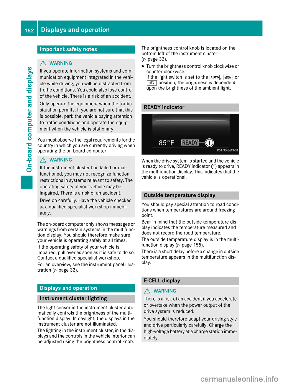
When the drive system is started and the vehicle
is ready to drive, READY indicator 0043appears in
the multifunction display. This indicates that the vehicle is operational. Outside temperature display
You should pay special attention to road condi-
tions when temperatures are around freezing
point.
Bear in mind that the outside temperature dis-
play indicates the temperature measured and
does not record the road temperature.
The outside temperature display is in the multi-
function display (Y page 155).
There is a short delay before a change in outside
temperature appears in the multifunction dis-
play. E-CELL display
G
WARNING
There is a risk of an accident if you accelerate or overtake when the power output of the
drive system is reduced.
You should therefore adapt your driving style
and drive particularly carefully. Charge the
high-voltage battery at a charge station imme- diately. 152
Displays and operationOn-board computer and displays
Page 162 of 290
Audio menu
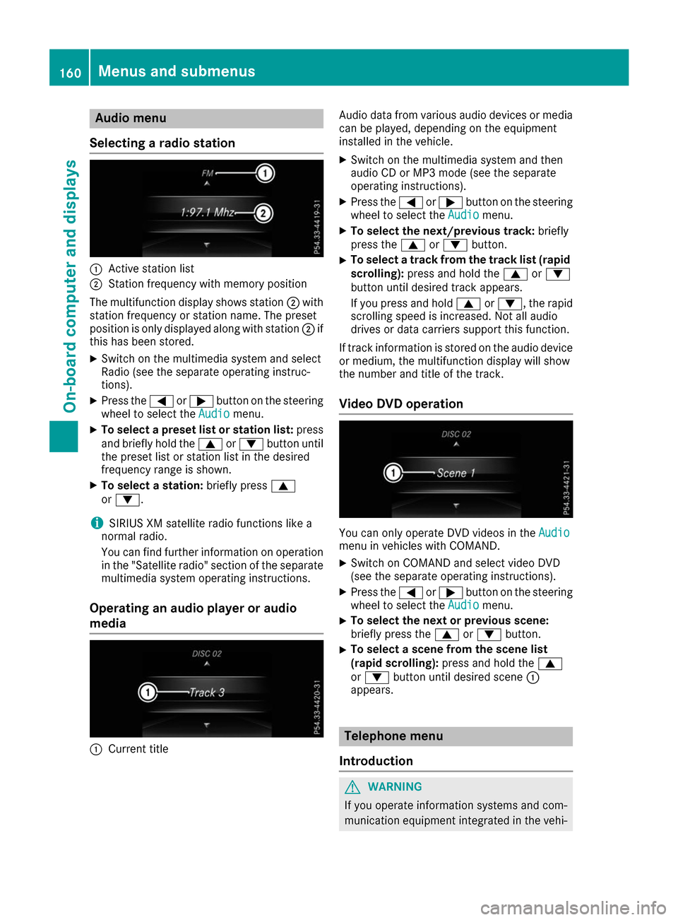
Selecting a radio station 0043
Active station list
0044 Station frequency with memory position
The multifunction display shows station 0044with
station frequency or station name. The preset
position is only displayed along with station 0044if
this has been stored.
X Switch on the multimedia system and select
Radio (see the separate operating instruc-
tions).
X Press the 0059or0065 button on the steering
wheel to select the Audio
Audio menu.
X To select a preset list or station list: press
and briefly hold the 0063or0064 button until
the preset list or station list in the desired
frequency range is shown.
X To select a station: briefly press0063
or 0064.
i SIRIUS XM satellite radio functions like a
normal radio.
You can find further information on operation in the "Satellite radio" section of the separate
multimedia system operating instructions.
Operating an audio player or audio
media 0043
Current title Audio data from various audio devices or media
can be played, depending on the equipment
installed in the vehicle.
X Switch on the multimedia system and then
audio CD or MP3 mode (see the separate
operating instructions).
X Press the 0059or0065 button on the steering
wheel to select the Audio Audiomenu.
X To select the next/previous track: briefly
press the 0063or0064 button.
X To select a track from the track list (rapid
scrolling): press and hold the 0063or0064
button until desired track appears.
If you press and hold 0063or0064, the rapid
scrolling speed is increased. Not all audio
drives or data carriers support this function.
If track information is stored on the audio device or medium, the multifunction display will show
the number and title of the track.
Video DVD operation You can only operate DVD videos in the
Audio Audio
menu in vehicles with COMAND.
X Switch on COMAND and select video DVD
(see the separate operating instructions).
X Press the 0059or0065 button on the steering
wheel to select the Audio
Audiomenu.
X To select the next or previous scene:
briefly press the
0063or0064 button.
X To select a scene from the scene list
(rapid scrolling): press and hold the 0063
or 0064 button until desired scene 0043
appears. Telephone menu
Introduction G
WARNING
If you operate information systems and com-
munication equipment integrated in the vehi- 160
Menus and sub
menusOn-board computer and displays
Page 203 of 290
General notes
The multimedia system section in this Opera-
tor's Manual describes the basic principles for
operation. More information can be found in the Digital Operator's Manual. Important safety notes
G
WARNING
If you operate information systems and com-
munication equipment integrated in the vehi- cle while driving, you will be distracted from
traffic conditions. You could also lose control of the vehicle. There is a risk of an accident.
Only operate the equipment when the traffic
situation permits. If you are not sure that this
is possible, park the vehicle paying attention
to traffic conditions and operate the equip-
ment when the vehicle is stationary.
You must observe the legal requirements for the country in which you are currently driving whenoperating the multimedia system.
The multimedia system calculates the route to
the destination without taking the following into
account, for example:
R traffic lights
R stop and yield signs
R parking or stopping restrictions
R road narrowing
R other road and traffic rules and regulations
The multimedia system may give incorrect nav-
igation recommendations if the actual street/
traffic situation does not correspond with the
digital map's data.
For example:
R a diverted route
R the road layout or the direction of a one-way
street has been changed
For this reason, you must always observe road
and traffic rules and regulations during your
journey. Road and traffic rules and regulations
always have priority over multimedia system
driving recommendations.
Navigation announcements are intended to
direct you while driving without diverting your
attention from the road and driving. Please always use this feature instead of con-
sulting the map display for directions. Looking
at the icons or map display can distract you from traffic conditions and driving, and increase the
risk of an accident.
This equipment complies with FCC radiation
exposure limits set forth for uncontrolled equip-
ment and meets the FCC radio frequency (RF)
Exposure Guidelines in Supplement C to OET65.
This equipment has very low levels of RF energy that is deemed to comply without maximum
permissive exposure evaluation (MPE). How-
ever, it is recommended to install it at a distance
of at least 8 inches (approx. 20 cm) between the
radiation source and a person's body (not
including limbs such as hands, wrists, feet and
legs). G
WARNING
Modifications to electronic components, their software as well as wiring can impair their
function and/or the function of other net-
worked components. In particular, systems
relevant to safety could also be affected. As a
result, these may no longer function as inten-
ded and/or jeopardize the operating safety of
the vehicle. There is an increased risk of an
accident and injury.
Never tamper with the wiring as well as elec-
tronic components or their software. You
should have all work to electrical and elec-
tronic equipment carried out at a qualified
specialist workshop.
If you make any changes to the vehicle elec-
tronics, the general operating permit is ren-
dered invalid. Function restrictions
For safety reasons, some functions are restric-
ted or unavailable while the vehicle is in motion. You will notice this, for example, because either
you will not be able to select certain menu items or a message will appear to this effect. Function restrictions
201Multimedia system Z