MERCEDES-BENZ B-Class ELECTRIC 2016 W246 Owner's Manual
Manufacturer: MERCEDES-BENZ, Model Year: 2016, Model line: B-Class ELECTRIC, Model: MERCEDES-BENZ B-Class ELECTRIC 2016 W246Pages: 342, PDF Size: 7.53 MB
Page 141 of 342
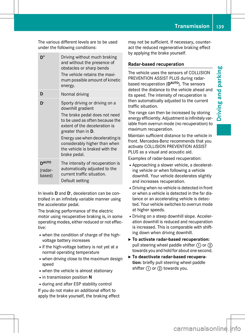
The various different levels are to be used
under the following conditions:
D+Driving without much braking
and without the presence of
obstacles or sharp bends
The vehicle retains the maxi-
mum possible amount of kinetic
energy.
DNormal driving
D-Sporty driving or driving on a
downhill gradient
The brake pedal does not need
to be used as often because the
extent of the deceleration is
greater than inD.
Energy use when decelerating is
considerably higher than when
the vehicle is braked with the
brake pedal.
DAUTO
(radar-
based)
The intensity of recuperation is
automatically adjusted to the
current traffic situation.
Default setting
In levels Dand D-, deceleration can be con-
trolled in an infinitely variable manner using
the accelerator pedal.
The braking performance of the electric
motor using recuperative braking is, in some
operating modes, either reduced or not effec-
tive:
Rwhen the condition of charge of the high-
voltage battery increases
Rif the high-voltage battery is not yet at a
normal operating temperature
Rwhen driving close to the maximum design
speed
Rwhen the vehicle is almost stationary
Rin transmission position N
Rduring and after ESP stability control
If you do not make an additional effort to
apply the brake yourself, the braking effect may not be sufficient. If necessary, counter-
act the reduced regenerative braking effect
by applying the brake yourself.
Radar-based recuperation
The vehicle uses the sensors of COLLISION
PREVENTION ASSIST PLUS during radar-
based recuperation (D
AUTO). The sensors
detect the distance to the vehicle ahead and
its speed. The intensity of recuperation is
then automatically adjusted to the current
traffic situation.
The range can then be increased by storing
energy efficiently. Adjustment is infinitely var-
iable from overrun mode (no recuperation) to
maximum recuperation.
Maintain sufficient distance to the vehicle in
front. Mercedes-Benz recommends that you
activate COLLISION PREVENTION ASSIST
PLUS as a visual and acoustic aid.
Examples of radar-based recuperation:
RApproaching a slower vehicle, a decelerat-
ing vehicle or when following a vehicle
downhill. Your vehicle decelerates slightly
and increases recuperation.
RDriving when no vehicle is detected in front
or when a vehicle is detected in the far dis- tance or an accelerating vehicle is detec-
ted. Your vehicle switches to overrun mode
at higher speeds.
RDriving on a steep downhill slope. Acceler-
ation downhill is reduced and recuperation
is increased. This is comparable with shift-
ing down when driving downhill.
XTo activate radar-based recuperation:
pull steering wheel paddle shifter :or;
towards you and hold for about one second.
XTo deactivate radar-based recupera-
tion: briefly pull steering wheel paddle
shifter :or; towards you.
Transmission139
Driving and parking
Z
Page 142 of 342
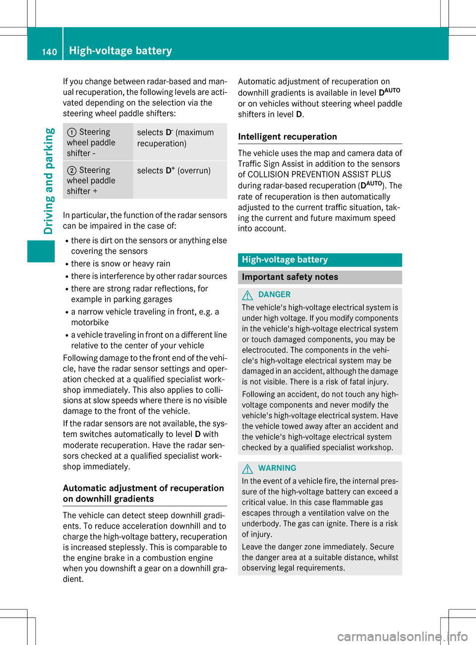
If you change between radar-based and man-
ual recuperation, the following levels are acti-
vated depending on the selection via the
steering wheel paddle shifters:
:Steering
wheel paddle
shifter -selects D-(maximum
recuperation)
; Steering
wheel paddle
shifter +selects D+(overrun)
In particular, the function of the radar sensors
can be impaired in the case of:
Rthere is dirt on the sensors or anything else
covering the sensors
Rthere is snow or heavy rain
Rthere is interference by other radar sources
Rthere are strong radar reflections, for
example in parking garages
Ra narrow vehicle traveling in front, e.g. a
motorbike
Ra vehicle traveling in front on a different line
relative to the center of your vehicle
Following damage to the front end of the vehi-
cle, have the radar sensor settings and oper-
ation checked at a qualified specialist work-
shop immediately. This also applies to colli-
sions at slow speeds where there is no visible
damage to the front of the vehicle.
If the radar sensors are not available, the sys-
tem switches automatically to level Dwith
moderate recuperation. Have the radar sen-
sors checked at a qualified specialist work-
shop immediately.
Automatic adjustment of recuperation
on downhill gradients
The vehicle can detect steep downhill gradi-
ents. To reduce acceleration downhill and to
charge the high-voltage battery, recuperation
is increased steplessly. This is comparable to
the engine brake in a combustion engine
when you downshift a gear on a downhill gra-
dient. Automatic adjustment of recuperation on
downhill gradients is available in level
D
AUTO
or on vehicles without steering wheel paddle
shifters in levelD.
Intelligent recuperation
The vehicle uses the map and camera data of
Traffic Sign Assist in addition to the sensors
of COLLISION PREVENTION ASSIST PLUS
during radar-based recuperation (D
AUTO). The
rate of recuperation is then automatically
adjusted to the current traffic situation, tak-
ing the current and future maximum speed
into account.
High-voltage battery
Important safety notes
GDANGER
The vehicle's high-voltage electrical system is under high voltage. If you modify components
in the vehicle's high-voltage electrical system
or touch damaged components, you may be
electrocuted. The components in the vehi-
cle's high-voltage electrical system may be
damaged in an accident, although the damage
is not visible. There is a risk of fatal injury.
Following an accident, do not touch any high-
voltage components and never modify the
vehicle's high-voltage electrical system. Have
the vehicle towed away after an accident and
the vehicle's high-voltage electrical system
checked by a qualified specialist workshop.
GWARNING
In the event of a vehicle fire, the internal pres- sure of the high-voltage battery can exceed a
critical value. In this case flammable gas
escapes through a ventilation valve on the
underbody. The gas can ignite. There is a risk
of injury.
Leave the danger zone immediately. Secure
the danger area at a suitable distance, whilst
observing legal requirements.
140High-voltage battery
Driving and parking
Page 143 of 342
GDANGER
If you use incorrectly installed mains sockets or adapters, extension cables or similar to
connect thecharging cable to a mains socket,
this could lead to fires or an electric shock.
There is a risk of fatal injury.
To avoid hazardous situations, observe the
following:
ROnly connect the charging cable to mains
sockets that:
-are installed correctly and
-have been approved by an electrical spe-
cialist.
RFo r safety reasons, only use the charging
cables supplied with the vehicle, or charg-
ing cables which have been approved for
use with this vehicle.
RNever use a damaged charging cable.
RDo not use:
-Extension cables
-Cable drums
-Multiple sockets
RDo no t use a socket adapter to connect the
charging cable to th e mains socket. The
only exception is if the adapter has been
tested and approved by the manufacturer
for charging th e high-voltage battery in an
electric vehicle.
RAlways observe the safety notes in the
socket adapter's operating instructions.
GDANGER
Connecting the charging cable to th e wallbox
via an incorrectly installed wallbox or adapter,
extension cable or similar could causeafire or
an electric shock. There is a risk of fatal injury.
To avoid hazardous situations, observe the
following:
ROnly connect thecharging cable to a wall-
box that:
-is installed correctly and
-has been approved by an electrical spe-
cialist.
RFo r safety reasons, only use charging
cables that have been tested and approved
by the manufacturer for charging the high-
voltage battery in an electric vehicle.
RNever use damaged charging cables.
RDo no textend th e charging cable.
RDo not use an adapter.
RAlways observe the safety notes in the wall-
box's operating instructions.
The vehicle's high voltage electrical system is
under high voltage.
RDo no t handle high-voltage components or
th e orange cables of the vehicle's high-volt-
age electrical system.
RDo no t touch high-voltage components or
th e orange cables of the high-voltage elec-
trical system when a vehicle has been
involved in a crash.
RDo no ttouch any damaged components or
damaged orange cables of the vehicle's
high-voltage electrical system.
RDo no tremove th ecover s of the high-volt-
age electrical system components that are
marke d withawarning sticker.
Notes on the charging cable
Handling the charg ing cable and charg -
ing cable controls
Do no t leave thecharging cable control s
(
Ypage 147) hanging loose from an electrical
outlet. Otherwise, this could result in a poor
contact with the electrical outlet and mal-
functions when charging the vehicle.
High-voltage battery141
Driving and parking
Z
Page 144 of 342
To ensure that the brackets within the charg-
ing cable controls are not subjected to incor-
rect loads, observe the following:
RNever lift or carry the controls by the charg-ing cable connector or the mains plug.
RTo transport the charging cable, the coiled
part can be:
-wrapped around the controls or
-secured to the housing of the controls
Heat generated by the charging cable
and charging cable connector
Pay attention to the important safety notes
(
Ypage 140).
During the charging process, the charging
cable and charging cable connector may heat
up.
The charging cable and charging cable con-
nector will only heat up within the permissible
limiting values, provided that:
Rthe power supply and the charging cable
are not damaged
Rthe instructions for handling the charging
cable and controls on the charging cable
are observed
Should the permissible heating temperature
limits be exceeded, have the mains power
supply checked.
Protection device against overvoltage
!Voltage surges in the mains supply can
damage the vehicle. The vehicle is there-
fore equipped with a device which protects
it from voltage surges in the mains supply.
This device may be triggered during severe
thunderstorms, for example, and may lead
to the building's fuse being tripped and an
interruption in the power supply. These
functions protect the vehicle. After the
building fuse is switched on again, the
charging process resumes automatically.
Following an interruption in the power sup- ply without tripping of the building's fuse, it may take up to 15 minutes for charging to
resume automatically.
Switch on the building's fuse again after the
protection device against overvoltage has
been triggered. Otherwise, the charging proc-
ess cannot be continued. The high-voltage
battery will not be charged and you may not
be able to drive the vehicle.
If other devices are protected by the same
protective device, these are switched off as
well when the protective device is triggered.
Ensure that these other devices are still
operational after reactivating the protection
device.
Influences on the charging behavior
and the charge state of the high-volt-
age battery
Terms of use
Observe the following notes:
Rinformation on exceptions and limitations
in warranty documentation and in the rela-
ted Maintenance Booklet
Rmaintenance notes for the high-voltage
battery in the Maintenance Booklet
Method of operation
The vehicle is equipped with a high-voltage
battery for driving. The high-voltage battery
stores the energy needed to operate the elec-
tric motor and releases it again.
The electric motor uses energy that has been
stored in the high-voltage battery when pull-
ing away, accelerating and during the jour-
ney.
In overrun mode (except D+), kinetic energy
is converted by means of energy recuperation
into electrical energy and stored in the high-
voltage battery.
142High-voltage battery
Driving and parking
Page 145 of 342
The high-voltage battery can be charged as
follows:
Rthrough energy recuperation while the
vehicle is in motion
Rwith the charging cable at a mains socket
while the vehicle is stationary
Rwith the charging cable at a charging sta-
tion while the vehicle is stationary
The high-voltage battery can be charged
using a single-phase charging cable in a volt-
age range from 100 V to 240 V.
If the condition of charge drops to less than
13%, the high-voltage battery reserve indica-
tor lamp lights up in the instrument cluster.
Charge the high-voltage battery as soon as
possible.
Below a condition of charge of 5%, the per-
formance of the vehicle is reduced. The vehi-
cle's high-voltage electrical system switches
off at a condition of charge of 0%.
Use of the pre-entry climate control function
may mean that the high-voltage battery is not
fully charged.
High and low outside temperatures
Low outside temperatures
The efficiency of the high-voltage battery is
significantly reduced at very low outside tem-
peratures. The high-voltage battery is then no longer able to provide the normal electrical
power output.
High outside temperatures
To prevent damage to the high-voltage bat-
tery due to very high outside temperatures,
the maximum power output of the high-volt-
age battery is reduced automatically.
The E-CELL display indicates the maximum
amount of power available (
Ypage 183).
Notes on battery care
Avoid storing or transporting the vehicle in
high temperatures over a long period (e.g.
container transport). If you park the vehicle and leave it stationary
for longer periods, connect it to a power sup-
ply.
Temperatures below
Ò13‡(Ò25 †) and over
104 ‡ (40 †), which affect the vehicle for a
period of more than seven days, can cause
irreversible damage.
Discharged battery
The vehicle's high-voltage electrical system
switches off if the high-voltage battery is com-
pletely discharged. 30 seconds prior to this,
you are informed of the switch-off by the
Battery level too low. Stop and
charge immediatelymessage. This pro-
tects the battery from exhaustive discharge.
It is not possible to restart the drive system
until after charging.
Do not leave the vehicle parked for longer
than 14 days with a high-voltage battery con- dition of charge below 20%.
You can check the condition of charge in the
charge level display (
Ypage 184).
Further information on the "Energy flow dis-
play" can be found in the "Trip" menu
(
Ypage 187).
Energy consumption and range
This range is reduced by:
Rhigh and low outside temperatures
Ra non-anticipatory driving style
Rswitching on consumers, e.g. air-condition-
ing system or heating.
The battery's physical characteristics are
such that leaving the vehicle parked for an
extended period at low outdoor temperatures
without charging it can lead to:
Ra reduction in battery performance
Rlonger charge times
In extreme cases, this could mean that the
vehicle cannot be started. For this reason,
connect the charging cable when leaving the
vehicle parked for long periods at low outdoor
temperatures.
High-voltage battery143
Driving and parking
Z
Page 146 of 342
As a result of its basic characteristics, the
amount of energy available from the high-
voltage battery decreases over the course of
its life.
This reduces:
Rthe maximum range that can be achieved
by the vehicle
Rthe maximum output (acceleration) of the
vehicle
You can actively reduce the energy consump-
tion of your vehicle in a number of ways, for
example, by:
Ran anticipatory driving style
Rreducing the use of electrical consumers
Rhaving the vehicle regularly maintained
The charging time of the high-voltage battery may change over the course of its life.
Observe the displays on energy usage
(
Ypage 188) and range (Ypage 188).
RANGE PLUS
If you activate RANGE PLUS, the operating
window of the battery will be extended at thenext charging process. An extended driving
range will be available to you for the next
journey.
Using RANGE PLUS shortens the service life
of the battery. Therefore, only use RANGE
PLUS if, for example:
Rlong journeys are planned or
Rthe availability of charging stations at the
destination is limited
The more often RANGE PLUS is used, the
more the extended range is reduced.
Therefore always check the range display
before every journey (
Ypage 188).
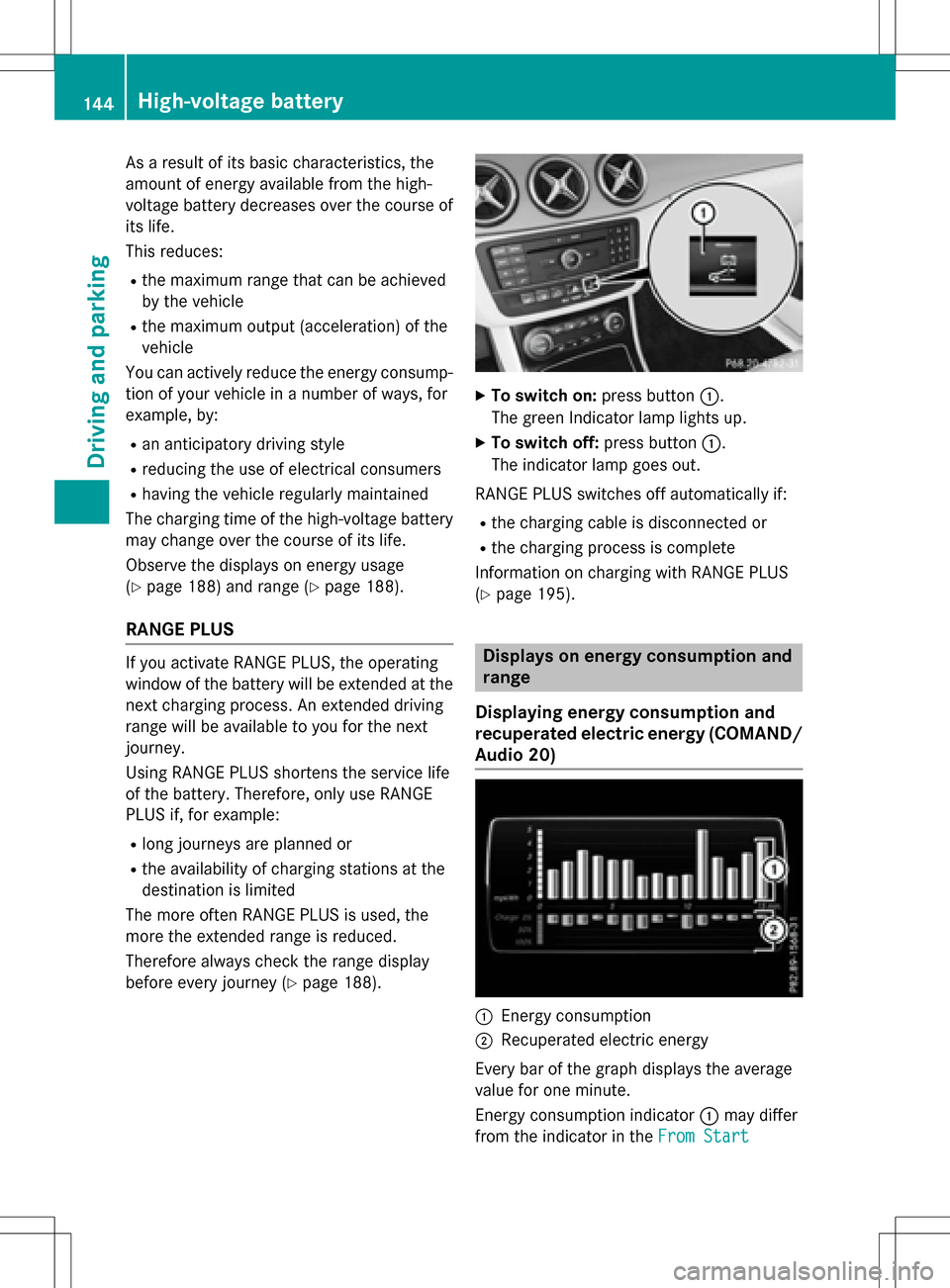
XTo switch on: press button:.
The green Indicator lamp lights up.
XTo switch off: press button:.
The indicator lamp goes out.
RANGE PLUS switches off automatically if:
Rthe charging cable is disconnected or
Rthe charging process is complete
Information on charging with RANGE PLUS
(
Ypage 195).
Displays on energy consumption and
range
Displaying energy consumption and
recuperated electric energy (COMAND/
Audio 20)
:Energy consumption
;Recuperated electric energy
Every bar of the graph displays the average
value for one minute.
Energy consumption indicator :may differ
from the indicator in the From Start
144High-voltage battery
Driving and parking
Page 147 of 342
(Ypage 187) trip computer in theTrip
menu.
Displaying energy consumption and recu-
perated electric energy:
XSwitch on Audio 20/COMAND (see the
separate operating instructions).
XTo select Vehiclefrom the main function
bar: turn and press the controller.
The vehicle menu is displayed.
XTo select Consumption: turn and press the
controller.
Energy consumption :and recuperated
electric energy ;for the last 15 minutes of
the journey are shown.
Exiting the vehicle settings:
XPress the %button on the controller.
or
XTo select %: slide 6and press the
controller.
To reset values: the values are reset along
with the From Start
trip computer
(
Ypage 189).
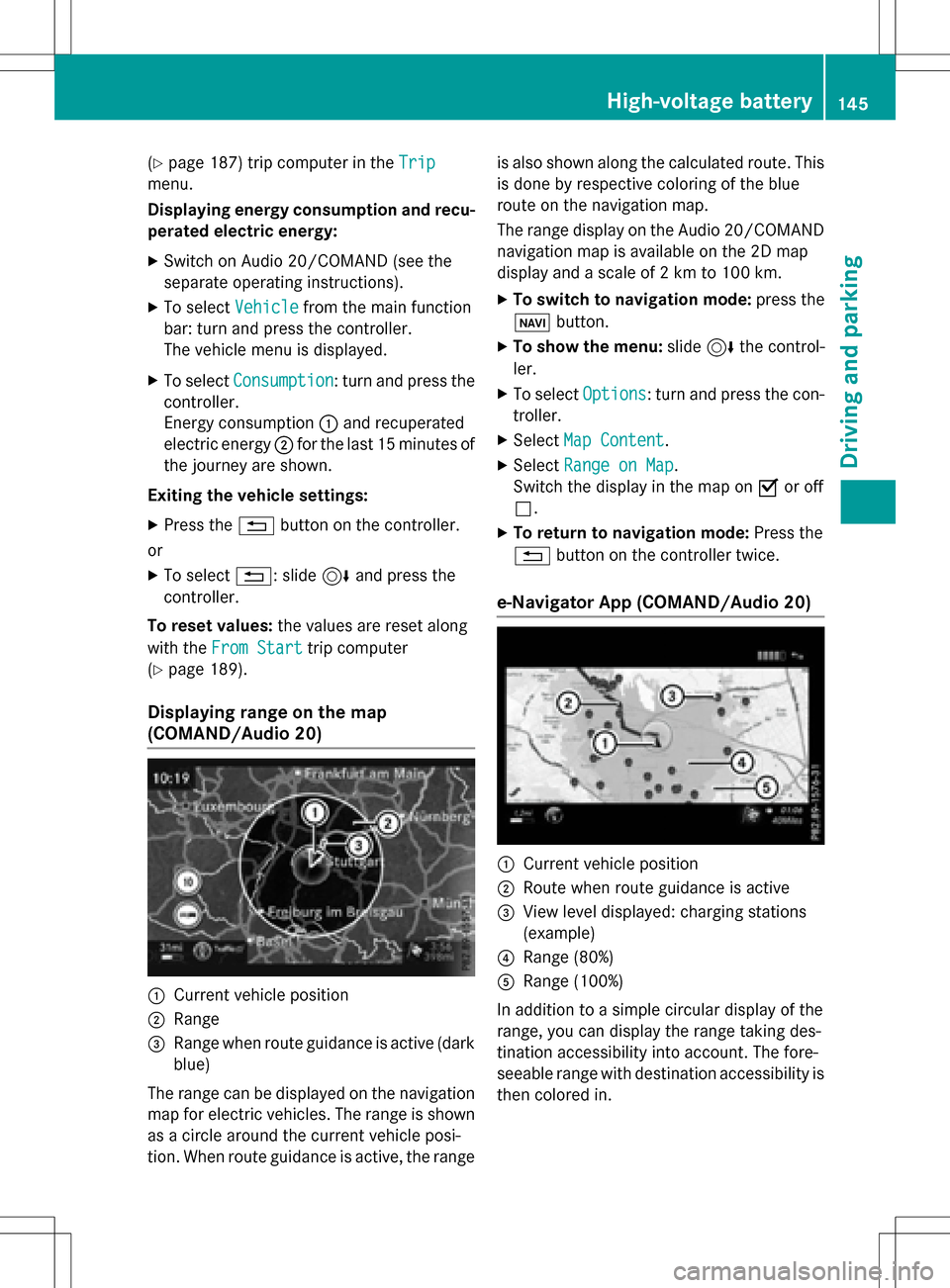
Displaying range on the map
(COMAND/Audio 20)
:Current vehicle position
;Range
=Range when route guidance is active (dark
blue)
The range can be displayed on the navigation
map for electric vehicles. The range is shown
as a circle around the current vehicle posi-
tion. When route guidance is active, the range is also shown along the calculated route. This
is done by respective coloring of the blue
route on the navigation map.
The range display on the Audio 20/COMAND
navigation map is available on the 2D map
display and a scale of 2 km to 100 km.
XTo switch to navigation mode:
press the
ß button.
XTo show the menu: slide6the control-
ler.
XTo select Options: turn and press the con-
troller.
XSelect Map Content.
XSelectRange on Map.
Switch the display in the map on Oor off
ª.
XTo return to navigation mode: Press the
% button on the controller twice.
e-Navigator App (COMAND/Audio 20)
:Current vehicle position
;Route when route guidance is active
=View level displayed: charging stations
(example)
?Range (80%)
ARange (100%)
In addition to a simple circular display of the
range, you can display the range taking des-
tination accessibility into account. The fore-
seeable range with destination accessibility is
then colored in.
High-voltage battery145
Driving and parking
Z
Page 148 of 342
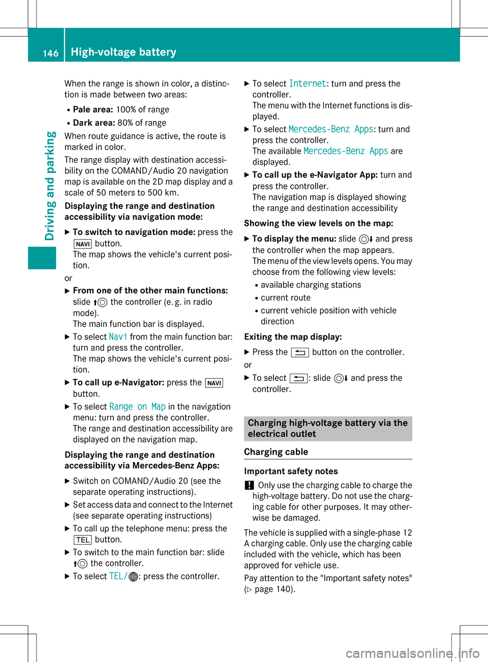
When the range is shown in color, a distinc-
tion is made between two areas:
RPale area:100% of range
RDark area: 80% of range
When route guidance is active, the route is
marked in color.
The range display with destination accessi-
bility on the COMAND/Audio 20 navigation
map is available on the 2D map display and a scale of 50 meters to 500 km.
Displaying the range and destination
accessibility via navigation mode:
XTo switch to navigation mode: press the
ß button.
The map shows the vehicle's current posi-
tion.
or
XFrom one of the other main functions:
slide 5the controller (e. g. in radio
mode).
The main function bar is displayed.
XTo select Navifrom the main function bar:
turn and press the controller.
The map shows the vehicle's current posi-
tion.
XTo call up e-Navigator: press theß
button.
XTo select Range on Mapin the navigation
menu: turn and press the controller.
The range and destination accessibility are
displayed on the navigation map.
Displaying the range and destination
accessibility via Mercedes-Benz Apps:
XSwitch on COMAND/Audio 20 (see the
separate operating instructions).
XSet access data and connect to the Internet
(see separate operating instructions)
XTo call up the telephone menu: press the
% button.
XTo switch to the main function bar: slide
5the controller.
XTo select TEL/®: press the controller.
XTo selectInternet: turn and press the
controller.
The menu with the Internet functions is dis-
played.
XTo select Mercedes-Benz Apps: turn and
press the controller.
The available Mercedes-Benz Apps
are
displayed.
XTo call up the e-Navigator App: turn and
press the controller.
The navigation map is displayed showing
the range and destination accessibility
Showing the view levels on the map:
XTo display the menu: slide6and press
the controller when the map appears.
The menu of the view levels opens. You may
choose from the following view levels:
Ravailable charging stations
Rcurrent route
Rcurrent vehicle position with vehicle
direction
Exiting the map display:
XPress the %button on the controller.
or
XTo select %: slide 6and press the
controller.
Charging high-voltage battery via the
electrical outlet
Charging cable
Important safety notes
!Only use the charging cable to charge the
high-voltage battery. Do not use the charg-
ing cable for other purposes. It may other-
wise be damaged.
The vehicle is supplied with a single-phase 12
A charging cable. Only use the charging cable
included with the vehicle, which has been
approved for vehicle use.
Pay attention to the "Important safety notes"
(
Ypage 140).
146High-voltage battery
Driving and parking
Page 149 of 342
If you use the supplied 12 A charging cable to
charge a high-voltage battery:
Rthe charge time increases considerably
Relectrical consumption increases consider-
ably
Where possible, charge the high-voltage bat-
tery at a charging station (
Ypage 149). Only
then can certified electrical energy consump-
tion levels be reached.
iThe charging process can vary depending
on the charging station. Therefore, always
observe the local information.
Stowing the charging cable
The charging cable can be stowed in a bag in
the trunk of the vehicle. To do so, the bag
must be secured to the cargo tie-down rings
using the retaining strap provided.
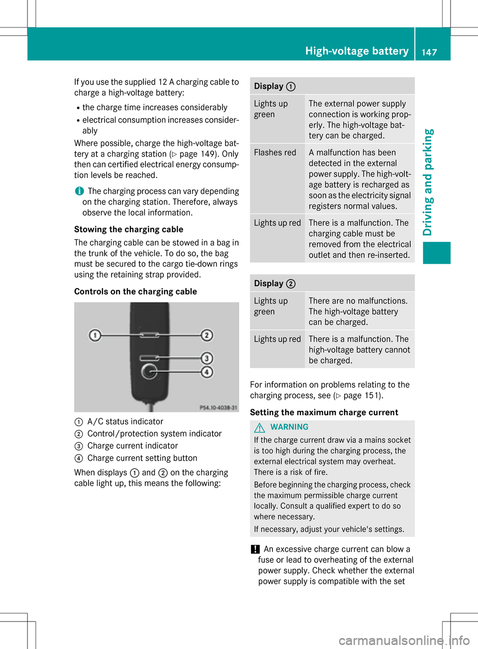
Controls on the charging cable
:A/C status indicator
;Control/protection system indicator
=Charge current indicator
?Charge current setting button
When displays :and ;on the charging
cable light up, this means the following:
Display :
Lights up
greenThe external power supply
connection is working prop-
erly. The high-voltage bat-
tery can be charged.
Flashes redA malfunction has been
detected in the external
power supply. The high-volt-
age battery is recharged as
soon as the electricity signal
registers normal values.
Lights up redThere is a malfunction. The
charging cable must be
removed from the electrical
outlet and then re-inserted.
Display;
Lights up
greenThere are no malfunctions.
The high-voltage battery
can be charged.
Lights up redThere is a malfunction. The
high-voltage battery cannot
be charged.
For information on problems relating to the
charging process, see (
Ypage 151).
Setting the maximum charge current
GWARNING
If the charge current draw via a mains socket
is too high during the charging process, the
external electrical system may overheat.
There is a risk of fire.
Before beginning the charging process, check
the maximum permissible charge current
locally. Consult a qualified expert to do so
where necessary.
If necessary, adjust your vehicle's settings.
!An excessive charge current can blow a
fuse or lead to overheating of the external
power supply. Check whether the external
power supply is compatible with the set
High-voltage battery147
Driving and parking
Z
Page 150 of 342
charge current. If necessary, lower the set
charge current or use another power
socket.
You can set a limit for the values of the charge
current used in charging the high-voltage bat-
tery. This acts as a means of preventing the
power supply from overloading. You can set
this limit by using the controls on the charging
cable or in the on-board computer's menu.
Only set the maximum charge current in the
on-board computer menu if there are no
charge current settings on the charging
cable.
The default standard value is the minimum
charge current setting. This corresponds to
the minimum available charge current from
the power supply.
iThe value of the maximum setting and the
relevant adjustment values may vary
depending on the country.
Before charging the high-voltage battery,
have the maximum permissible charge cur-
rent for the relevant power socket checked by
an electrician.
XTo adjust the setting: press button?
repeatedly until the desired setting is selec-
ted in display =.
RTwo LEDs are flashing: minimum setting
RAll LEDs are flashing: maximum setting
Information about the charging time
(
Ypage 338)
If, after the charging process, the charging
cable is:
Rleft connected to the power socket, the
currently selected values will be used for
the next charging process.
Rremoved from the power socket, the values
will be reset to the minimum setting for the
next charging process. You may then need
to reset the values of the maximum charge
current.
If the charge current values that have been
set on the charging cable and the on-board computer are different, the high-voltage bat-
tery is charged using the lower value.
If the vehicle requires more time than usual to
charge the high-voltage battery, check:
Rthe settings of the maximum charge cur-
rent on the controls of the charging cable
Rthe settings of the maximum charge cur-
rent in the menu of the on-board computer
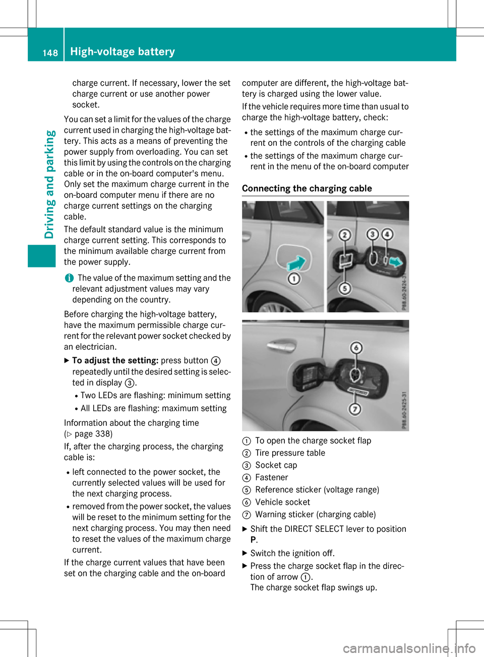
Connecting the charging cable
:To open the charge socket flap
;Tire pressure table
=Socket cap
?Fastener
AReference sticker (voltage range)
BVehicle socket
CWarning sticker (charging cable)
XShift the DIRECT SELECT lever to position
P.
XSwitch the ignition off.
XPress the charge socket flap in the direc-
tion of arrow
:.
The charge socket flap swings up.
148High-voltage battery
Driving and parking