steering MERCEDES-BENZ B-CLASS HATCHBACK 2011 Owner's Manual
[x] Cancel search | Manufacturer: MERCEDES-BENZ, Model Year: 2011, Model line: B-CLASS HATCHBACK, Model: MERCEDES-BENZ B-CLASS HATCHBACK 2011Pages: 329, PDF Size: 7.91 MB
Page 91 of 329
i
Further related subjects:
R Luggage compartment enlargement
(removing/folding the rea rbench seat
forwards) (Y page 248) Adjusting the seats manually
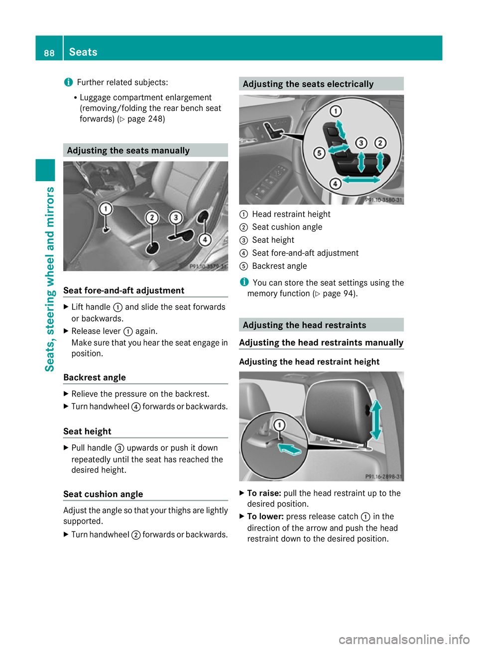
Seat fore-and-aft adjustment
X
Lift handle :and slide the seat forwards
or backwards.
X Release lever :again.
Make sure that you hear the seat engage in
position.
Backrest angle X
Relieve the pressure on the backrest.
X Turn handwheel ?forwards or backwards.
Seat height X
Pull handle =upwards or push it down
repeatedly until the seat has reached the
desired height.
Seat cushion angle Adjust the angle so that your thighs are lightly
supported.
X
Turn handwheel ;forwards or backwards. Adjusting the seats electrically
:
Head restraint height
; Seat cushion angle
= Seat height
? Seat fore-and-aft adjustment
A Backrest angle
i You can store the seat settings using the
memory function (Y page 94). Adjusting the head restraints
Adjusting the head restraints manually Adjusting the head restraint height
X
To raise: pull the head restraint up to the
desired position.
X To lower: press release catch :in the
direction of the arrow and push the head
restraint down to the desired position. 88
SeatsSeats, steering wheel and mirrors
Page 92 of 329
Adjusting the head restraint fore-and-aft
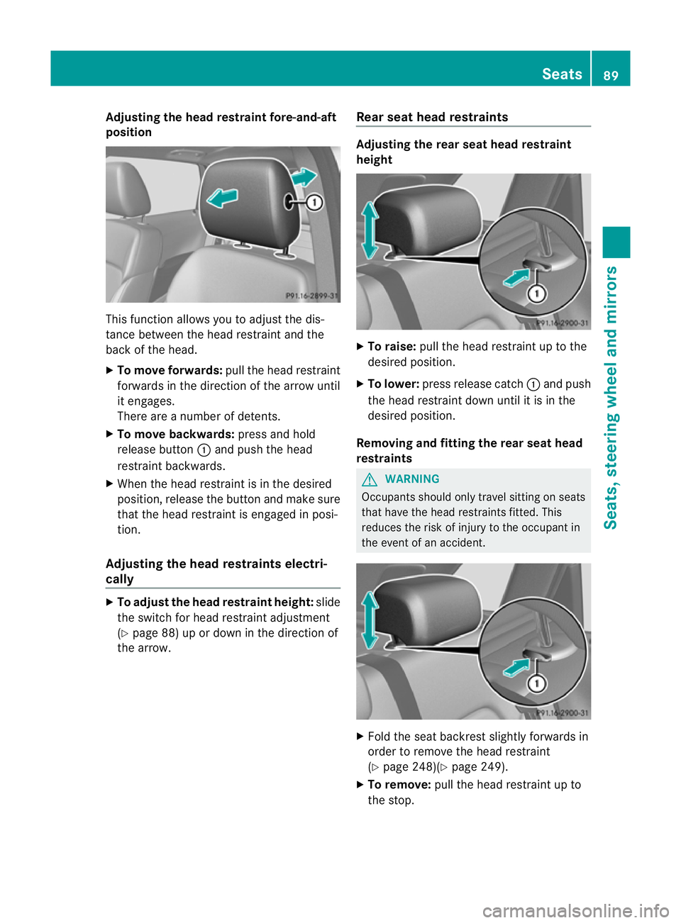
position
This function allows you to adjust the dis-
tance between the head restraint and the
back of the head.
X To move forwards: pull the head restraint
forwards in the direction of the arrow until
it engages.
There are a number of detents.
X To move backwards: press and hold
release button :and push the head
restraint backwards.
X When the head restraint is in the desired
position, release the butto nand make sure
tha tthe head restraint is engaged in posi-
tion.
Adjusting the head restraints electri-
cally X
To adjust the head restraint height: slide
the switch for head restraint adjustment
(Y page 88) up or down in the direction of
the arrow. Rear seat head restraints Adjusting the rear seat head restraint
height
X
To raise: pull the head restraint up to the
desired position.
X To lower: press release catch :and push
the head restraint down until it is in the
desired position.
Removing and fitting the rear seat head
restraints G
WARNING
Occupants should only travel sitting on seats
that have the head restraints fitted. This
reduces the risk of injury to the occupant in
the event of an accident. X
Fold the seat backrest slightly forwards in
order to remove the head restraint
(Y page 248)( Ypage 249).
X To remove: pull the head restraint up to
the stop. Seats
89Seats, steering wheel and mirrors Z
Page 93 of 329
X
Press release catch :and pull the head
restraint out of the guides.
X To refit: insert the head restraint so that
the notches on the bar are on the left when
viewed in the direction of travel.
X Push the head restraint down until you hear
it engage in position. Adjusting the 4-way lumbar support
You can adjust the contour of the front seat
backrests individually to provide optimum
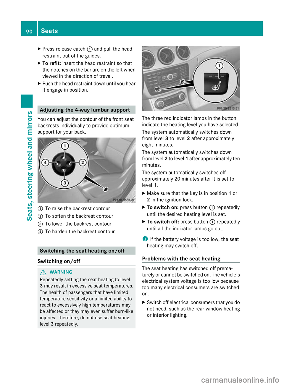
support for your back. :
To raise the backrest contour
; To soften the backrest contour
= To lower the backrest contour
? To harden the backrest contour Switching the seat heating on/off
Switching on/off G
WARNING
Repeatedly setting the seat heating to level
3 may result in excessive seat temperatures.
The health of passengers that have limited
temperature sensitivity or a limited ability to
react to excessively high temperatures may
be affected or they may even suffer burn-like
injuries. Therefore, do not use seat heating
level 3repeatedly. The three red indicator lamps in the button
indicate the heating level you have selected.
The system automatically switches down
from level
3to level 2after approximately
eight minutes.
The system automatically switches down
from level 2to level 1after approximately ten
minutes.
The system automatically switches off
approximately 20 minutes after it is set to
level 1.
X Make sure that the key is in position 1or
2 in the ignition lock.
X To switch on: press button:repeatedly
until the desired heating level is set.
X To switch off: press button:repeatedly
until all the indicator lamps go out.
i If the battery voltage is too low, the seat
heating may switch off.
Problems with the seat heating The seat heating has switched off prema-
turely or cannot be switched on. The vehicle's
electrical system voltage is too low because
too many electrical consumers are switched
on.
X Switch off electrical consumers that you do
not need, such as the rear window heating
or interior lighting. 90
SeatsSeats, steering wheel and mirrors
Page 94 of 329
Steering wheel
Important safety notes
G
WARNING
Only adjust the steering wheel when the vehi-
cle is stationary and make sure that it is
locked securely in position before driving off.
Driving without the steering wheel adjust-
ment mechanism being locked in position
may cause the steering wheel to move unex-
pectedly. As a result, the driver could lose
control of the vehicle. Before driving off make
sure that the steering wheel is properly locked
in position by trying to move it up and down. Adjusting the steering wheel
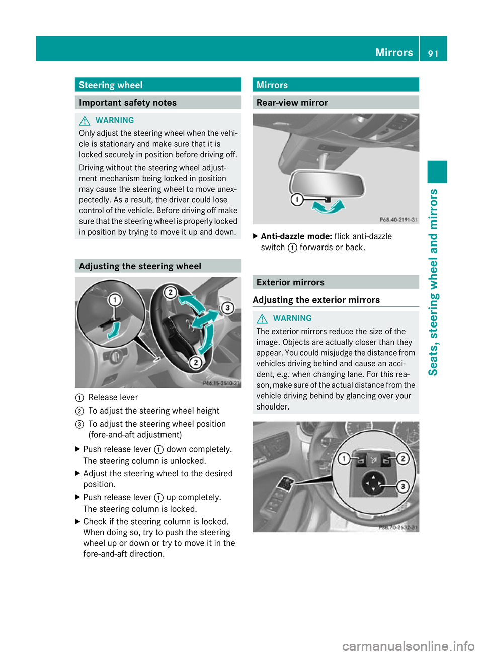
:
Release lever
; To adjust the steering wheel height
= To adjust the steering wheel position
(fore-and-aft adjustment)
X Push release lever :down completely.
The steering column is unlocked.
X Adjust the steering wheel to the desired
position.
X Push release lever :up completely.
The steering column is locked.
X Check if the steering column is locked.
When doing so, try to push the steering
wheel up or down or try to move it in the
fore-and-aft direction. Mirrors
Rear-view mirror
X
Anti-dazzle mode: flick anti-dazzle
switch :forwards or back. Exterior mirrors
Adjusting the exterior mirrors G
WARNING
The exterior mirrors reduce the size of the
image. Objects are actually closer than they
appear. You could misjudge the distance from
vehicles driving behind and cause an acci-
dent, e.g. when changing lane. For this rea-
son, make sure of the actual distance from the
vehicle driving behind by glancing over your
shoulder. Mirrors
91Seats, steering wheel and mirrors Z
Page 95 of 329
X
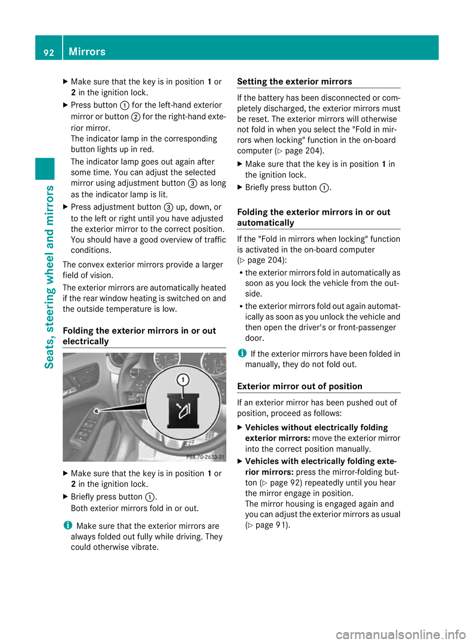
Make sure that the key is in position 1or
2 in the ignition lock.
X Press button :for the left-hand exterior
mirror or button ;for the right-hand exte-
rior mirror.
The indicator lamp in the corresponding
button lights up in red.
The indicator lamp goes out again after
some time. You can adjust the selected
mirror using adjustment button =as long
as the indicator lamp is lit.
X Press adjustment button =up, down, or
to the left or right until you have adjusted
the exterior mirror to the correct position.
You should have a good overview of traffic
conditions.
The convex exterior mirrors provide a larger
field of vision.
The exterior mirrors are automatically heated
if the rear window heating is switched on and
the outside temperature is low.
Folding the exterior mirrors in or out
electrically X
Make sure that the key is in position 1or
2 in the ignition lock.
X Briefly press button :.
Both exterior mirrors fold in or out.
i Make sure that the exterior mirrors are
always folded out fully while driving. They
could otherwise vibrate. Setting the exterior mirrors If the battery has been disconnected or com-
pletely discharged, the exterior mirrors must
be reset. The exterior mirrors will otherwise
not fold in when you select the "Fold in mir-
rors when locking" function in the on-board
computer (Y
page 204).
X Make sure that the key is in position 1in
the ignition lock.
X Briefly press button :.
Folding the exterior mirrors in or out
automatically If the "Fold in mirrors when locking" function
is activated in the on-board computer
(Y
page 204):
R the exterior mirrors fold in automatically as
soon as you lock the vehicle from the out-
side.
R the exterior mirrors fold out again automat-
ically as soon as you unlock the vehicle and
then open the driver's or front-passenger
door.
i If the exterior mirrors have been folded in
manually, they do not fold out.
Exterior mirror out of position If an exterior mirror has been pushed out of
position, proceed as follows:
X
Vehicles without electrically folding
exterior mirrors: move the exterior mirror
into the correct position manually.
X Vehicles with electrically folding exte-
rior mirrors: press the mirror-folding but-
ton (Y page 92) repeatedly until you hear
the mirror engage in position.
The mirror housing is engaged again and
you can adjust the exterior mirrors as usual
(Y page 91). 92
MirrorsSeats, steering wheel and mirrors
Page 96 of 329
Automatic anti-dazzle mirrors
G
WARNING
If inciden tlight fro mheadlamps is prevented
from striking the sensor in the rear-view mir-
ror, for instance, by luggage piled too high in
the vehicle, the mirror's automatic anti-dazzle
function will not operate.
Incident light could then blind you. This may
distract you from the traffic conditions and,
as a result, you may cause an accident.
The rear-view mirror and the exterior mirror
on the driver's side automatically go into anti-
dazzle mode if the ignition is switched on and
inciden tlight fro mheadlamps strikes the sen-
sor in the rear-view mirror.
The mirrors do not go into anti-dazzle mode if
reverse gear is engaged or if the interior light-
ing is switched on. Parking position for the exterior mir-
ror on the front-passenger side
Setting and storing the parking position You can position the front-passenger side
exterior mirror in such a way that you can see
the rear wheel on that side as soon as you
engage reverse gear. You can store this posi-
tion. X
Make sure that the vehicle is stationary and
that the key is in position 2in the ignition
lock.
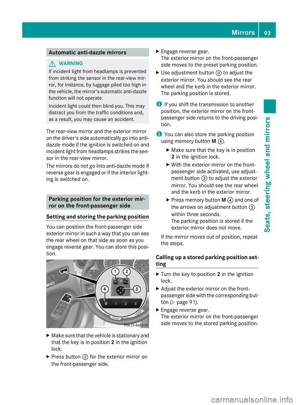
X Press button ;for the exterior mirror on
the front-passenger side. X
Engage reverse gear.
The exterior mirror on the front-passenger
side moves to the preset parking position.
X Use adjustment button =to adjust the
exterior mirror .You should see the rear
wheel and the kerb in the exterior mirror.
The parking position is stored.
i If you shift the transmission to another
position, the exterior mirror on the front-
passenger side returns to the driving posi-
tion.
i You can also store the parking position
using memory button M?.
X Make sure that the key is in position
2in the ignition lock.
X With the exterior mirror on the front-
passenger side activated, use adjust-
ment button =to adjust the exterior
mirror. You should see the rear wheel
and the kerb in the exterior mirror.
X Press memory button M? and one of
the arrows on adjustment button =
within three seconds.
The parking position is stored if the
exterior mirror does not move.
If the mirror moves out of position, repeat
the steps.
Calling up astore dparking position set-
ting X
Tur nthe key to position 2in the ignition
lock.
X Adjust the exterior mirror on the front-
passenger side with the corresponding but-
ton (Y page 91).
X Engage reverse gear.
The exterior mirror on the front-passenger
side moves to the stored parking position. Mirrors
93Seats, steering wheel and mirrors Z
Page 97 of 329
The exterior mirror on the front-passenger
side moves back to its original position:
R
as soon as you exceed a speed of
15 km/h
R about ten seconds after you have disen-
gaged reverse gear
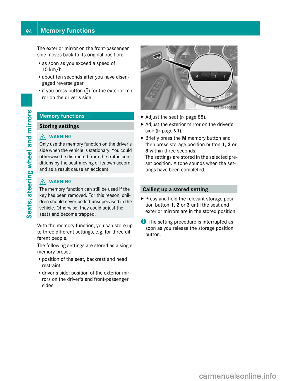
R if you press button :for the exterior mir-
ror on the driver's side Memory functions
Storing settings
G
WARNING
Only use the memory function on the driver's
side when the vehicle is stationary. You could
otherwise be distracted from the traffic con-
ditions by the seat moving of its own accord,
and as a result cause an accident. G
WARNING
The memory function can still be used if the
key has been removed. For this reason, chil-
dren should never be left unsupervised in the
vehicle. Otherwise, they could adjust the
seats and become trapped.
With the memory function, you can store up
to three different settings, e.g. for three dif-
ferent people.
The following settings are stored as a single
memory preset:
R position of the seat, backrest and head
restraint
R driver's side: position of the exterior mir-
rors on the driver's and front-passenger
sides X
Adjust the seat (Y page 88).
X Adjust the exterior mirror on the driver's
side (Y page 91).
X Briefly press the Mmemory button and
then press storage position button 1,2or
3 within three seconds.
The settings are stored in the selected pre-
set position. Atone sounds when the set-
tings have been completed. Calling up
astore dsetting
X Press and hold the relevant storage posi-
tion button 1,2or 3until the seat and
exterio rmirrors are in the stored position.
i The setting procedure is interrupted as
soon as you release the storage position
button. 94
Memory functionsSeats, steering wheel and mirrors
Page 103 of 329
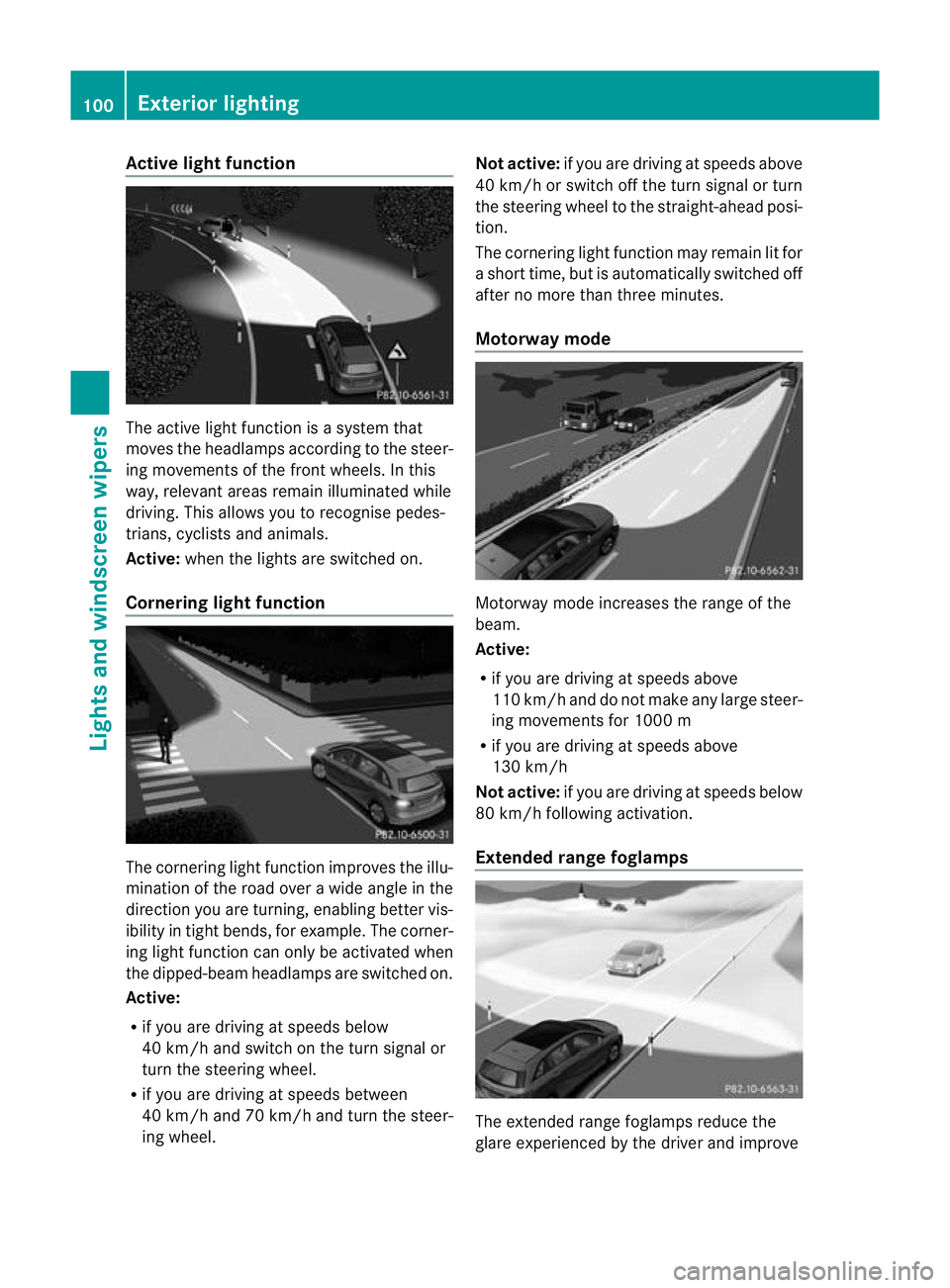
Active ligh
tfunction The active light function is a system that
moves the headlamps according to the steer-
ing movements of the front wheels. In this
way, relevant areas remai nilluminated while
driving. This allows you to recognise pedes-
trians, cyclists and animals.
Active: when the lights are switched on.
Cornering light function The cornering light function improves the illu-
mination of the road over a wide angle in the
direction you are turning, enabling better vis-
ibility in tigh
tbends, for example. The corner-
ing light function can only be activated when
the dipped-beam headlamps are switched on.
Active:
R if you are driving at speeds below
40 km/h and switch on the turn signal or
turn the steering wheel.
R if you are driving at speeds between
40 km/h and 70 km/h and turn the steer-
ing wheel. Not active:
if you are driving at speeds above
40 km/h or switch off the turn signal or turn
the steering wheel to the straight-ahead posi-
tion.
The cornering light function may remain lit for
a short time, but is automatically switched off
after no more than three minutes.
Motorway mode Motorway mode increases the range of the
beam.
Active:
R
if you are driving at speeds above
110 km/ha nd do not make any large steer-
ing movements for 1000 m
R if you are driving at speeds above
130 km/h
Not active: if you are driving at speeds below
80 km/h following activation.
Extended range foglamps The extended range foglamps reduce the
glare experienced by the driver and improve100
Exterior lightingLights and
windscreen wipers
Page 130 of 329
roads. Otherwise, you could damage the
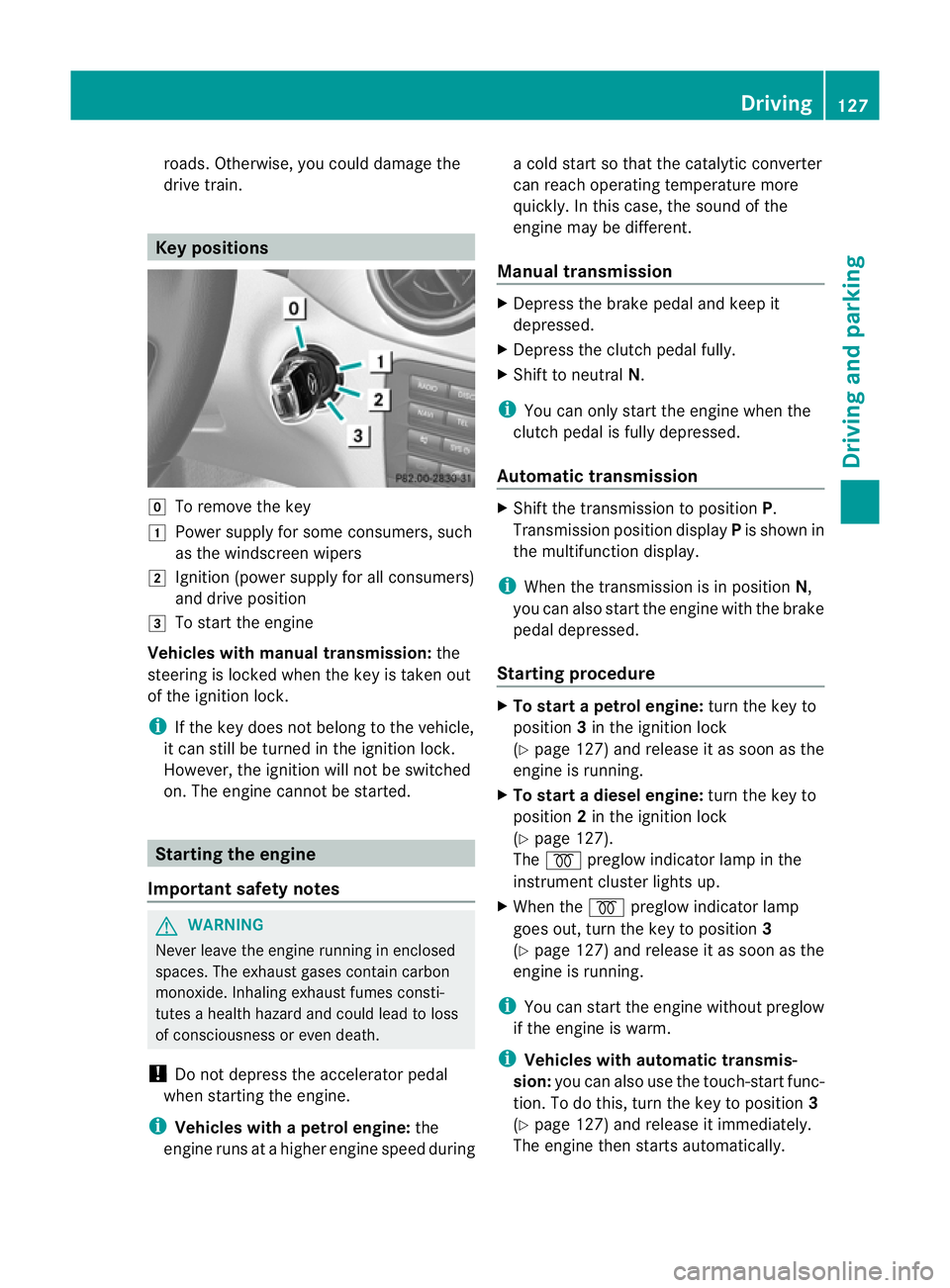
drive train. Keyp
ositions g
To remove the key
1 Power supply for some consumers, such
as the windscreen wipers
2 Ignitio n(power supply for all consumers)
and drive position
3 To start the engine
Vehicles with manual transmission: the
steering is locked when the key is taken out
of the ignition lock.
i If the key does not belong to the vehicle,
it can still be turned in the ignition lock.
However, the ignition will not be switched
on. The engine cannot be started. Starting the engine
Important safety notes G
WARNING
Never leave the engine running in enclosed
spaces. The exhaust gases contain carbon
monoxide. Inhaling exhaust fumes consti-
tutes a health hazard and could lead to loss
of consciousness or even death.
! Do not depress the accelerator pedal
when starting the engine.
i Vehicles with apetrol engine: the
engine runs at a highe rengine speed during a cold start so that the catalytic converter
can reach operating temperature more
quickly. In this case, the sound of the
engine may be different.
Manual transmission X
Depress the brake pedal and keep it
depressed.
X Depress the clutch pedal fully.
X Shift to neutral N.
i You can only start the engine when the
clutch pedal is fully depressed.
Automatic transmission X
Shift the transmission to position P.
Transmission positio ndisplay Pis shown in
the multifunction display.
i When the transmission is in position N,
you can also start the engine with the brake
pedal depressed.
Starting procedure X
To start a petrol engine: turn the key to
position 3in the ignition lock
(Y page 127) and release it as soon as the
engine is running.
X To start adiesel engine: turn the key to
position 2in the ignition lock
(Y page 127).
The % preglow indicator lamp in the
instrumen tcluster lights up.
X When the %preglow indicator lamp
goes out, tur nthe key to position 3
(Y page 127) and release it as soon as the
engine is running.
i You can start the engine without preglow
if the engine is warm.
i Vehicles with automatic transmis-
sion: you can also use the touch-start func-
tion. To do this, turn the key to position 3
(Y page 127) and release it immediately.
The engine then starts automatically. Driving
127Driving and parking Z
Page 138 of 329
Do not place several floormats on top of one
another.
G
WARNING
Do not change down for additional engine
braking on a slippery roa dsurface. This could
cause the drive wheels to lose their grip and
the vehicle could skid. This could cause you
to lose control of your vehicle and cause an
accident. G
WARNING
The clutch may overheat if you hold the vehi-
cle stationary on uphill gradients by depress-
ing the accelerato rpedal. If the clutch does
overheat, a warning tones ounds and a display
message is shown in the multifunction dis-
play. The frictional connection of the clutch
may then be interrupted. The vehicle may roll
away.A s a result, you could cause an acci-
dent.
You will only be able to continue you journey
once the clutch has cooled down and the dis-
play message in the multifunction display has
disappeared.
Never hold the vehicle stationary on uphill
gradients by depressing the accelerator.
Instead, only ever hold the vehicle stationary
on uphill gradients by
R depressing the brake pedal
or
R activating the HOLD function
or
R engaging the electric parking brake
i Bear in mind that the power transmission
between the engine and the transmission
is interrupted when the engine is switched
off. Therefore, to prevent the vehicle from
rolling away, shift the automatic transmis-
sion to park position Pand apply the elec-
tric parking brake when the engine is
switched off and the vehicle is stationary. DIRECTS
ELECT lever
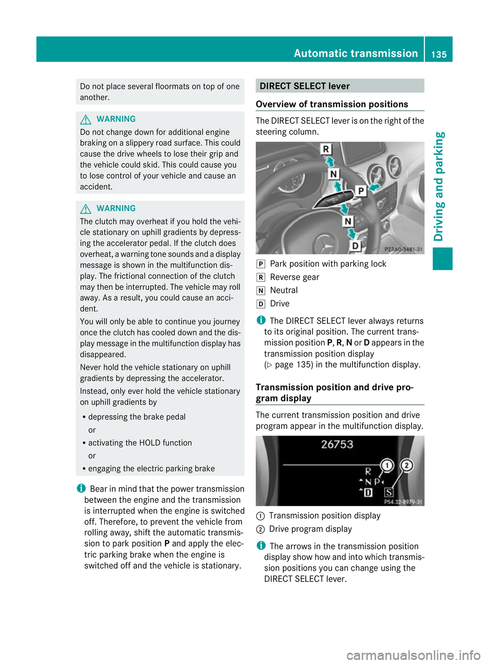
Overview of transmission positions The DIRECT SELECT leve
ris on the right of the
steering column. j
Park position with parking lock
k Reverse gear
i Neutral
h Drive
i The DIRECT SELECT lever always returns
to its original position. The current trans-
mission position P,R, Nor Dappears in the
transmission position display
(Y page 135) in the multifunction display.
Transmission position and drive pro-
gram display The current transmission position and drive
program appearint
he multifunction display. :
Transmission position display
; Drive program display
i The arrows in the transmission position
display show how and into which transmis-
sion positions you can change using the
DIRECT SELECT lever. Automatic transmission
135Driving and parking Z