manual transmission MERCEDES-BENZ B-CLASS HATCHBACK 2011 Owner's Guide
[x] Cancel search | Manufacturer: MERCEDES-BENZ, Model Year: 2011, Model line: B-CLASS HATCHBACK, Model: MERCEDES-BENZ B-CLASS HATCHBACK 2011Pages: 329, PDF Size: 7.91 MB
Page 203 of 329
X
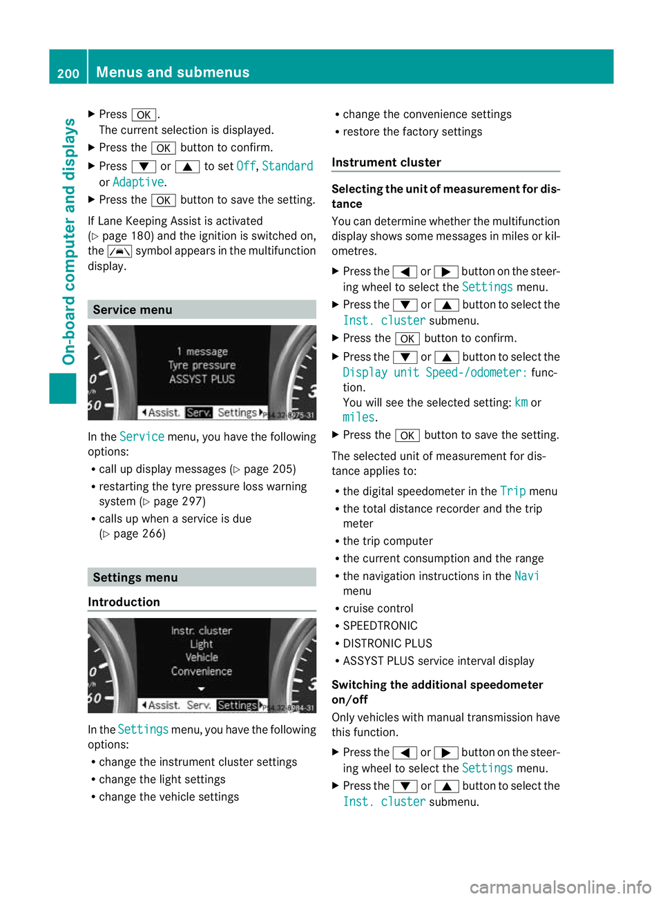
Press a.
The curren tselection is displayed.
X Press the abutton to confirm.
X Press :or9 to set Off ,
Standard or
Adaptive .
X Press the abutton to save the setting.
If Lane Keeping Assist is activated
(Y page 180)a nd the ignition is switched on,
the à symbol appears in the multifunction
display. Service menu
In the
Service menu, you have the following
options:
R call up display messages (Y page 205)
R restarting the tyre pressure loss warning
system (Y page 297)
R calls up when a service is due
(Y page 266) Settings menu
Introduction In the
Settings menu, you have the following
options:
R change the instrument cluster settings
R change the light settings
R change the vehicle settings R
change the convenience settings
R restore the factory settings
Instrument cluster Selecting the uni
tofmeasurement for dis-
tance
You can determine whether the multifunction
display shows some messages in miles or kil-
ometres.
X Press the =or; button on the steer-
ing wheel to selec tthe Settings menu.
X Press the :or9 button to select the
Inst. cluster submenu.
X Press the abutton to confirm.
X Press the :or9 button to select the
Display unit Speed-/odometer: func-
tion.
You will see the selected setting: km or
miles .
X Press the abutton to save the setting.
The selected unit of measurement for dis-
tance applies to:
R the digital speedometer in the Trip menu
R the total distance recorder and the trip
meter
R the trip computer
R the current consumption and the range
R the navigation instructions in the Navi menu
R cruise control
R SPEEDTRONIC
R DISTRONIC PLUS
R ASSYST PLUS service interval display
Switching the additional speedometer
on/off
Only vehicles with manual transmission have
this function.
X Press the =or; button on the steer-
ing wheel to select the Settings menu.
X Press the :or9 button to select the
Inst. cluster submenu.200
Menus and submenusOn-board computer and displays
Page 212 of 329
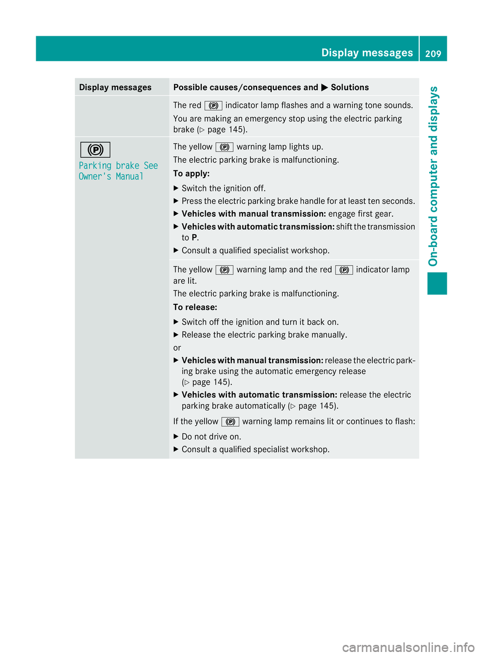
Display messages Possible causes/consequences and
M Solutions
The red
!indicato rlamp flashes and a warning tone sounds.
You are making an emergency stop using the electric parking
brake (Y page 145). !
Parking brake See
Owner's Manual The yellow
!warning lamp lights up.
The electric parking brake is malfunctioning.
To apply:
X Switch the ignition off.
X Press the electric parking brake handle for at least te nseconds.
X Vehicles with manual transmission: engage first gear.
X Vehicles with automatic transmission: shift the transmission
to P.
X Consult a qualified specialist workshop. The yellow
!warning lamp and the red !indicator lamp
are lit.
The electric parking brake is malfunctioning.
To release:
X Switch off the ignition and turn it back on.
X Release the electric parking brake manually.
or
X Vehicles with manual transmission: release the electric park-
ing brake using the automatic emergency release
(Y page 145).
X Vehicles with automatic transmission: release the electric
parking brake automatically ( Ypage 145).
If the yellow !warning lamp remains lit or continues to flash:
X Do not drive on.
X Consult a qualified specialist workshop. Display messages
209On-board computer and displays Z
Page 213 of 329
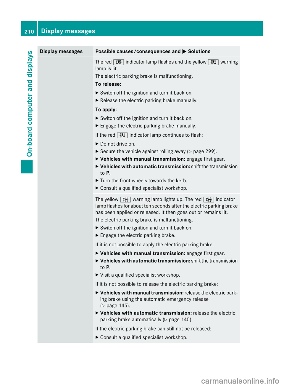
Display messages Possible causes/consequences and
M Solutions
The red
!indicato rlamp flashes and the yellow !warning
lamp is lit.
The electric parking brake is malfunctioning.
To release:
X Switch off the ignition and turn it back on.
X Release the electric parking brake manually.
To apply:
X Switch off the ignition and turn it back on.
X Engage the electric parking brake manually.
If the red !indicator lamp continues to flash:
X Do not drive on.
X Secure the vehicle against rolling away ( Ypage 299).
X Vehicles with manual transmission: engage first gear.
X Vehicles with automatic transmission: shiftthe transmission
to P.
X Turn the front wheels towards the kerb.
X Consult a qualified specialist workshop. The yellow
!warning lamp lights up. The red !indicator
lamp flashes for about ten seconds after the electric parking brake
has been applied or released. It then goes out or remains lit.
The electric parking brake is malfunctioning.
X Switch off the ignition and turn it back on.
X Engage the electric parking brake.
If it is not possible to apply the electric parking brake:
X Vehicles with manual transmission: engage first gear.
X Vehicles with automatic transmission: shift the transmission
to P.
X Visit a qualified specialist workshop.
If it is not possible to release the electric parking brake:
X Vehicles with manual transmission: release the electric park-
ing brake using the automatic emergency release
(Y page 145).
X Vehicles with automatic transmission: release the electric
parking brake automatically (Y page 145).
If the electric parking brake can still not be released:
X Consult a qualified specialist workshop. 210
Display messagesOn-board computer and displays
Page 214 of 329
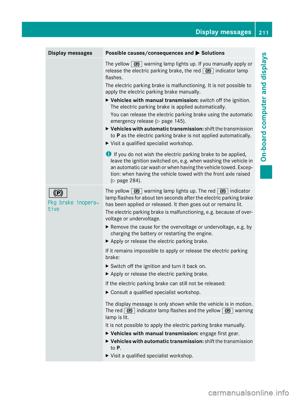
Display messages Possible causes/consequences and
M Solutions
The yellow
!warning lamp lights up. If you manually apply or
release the electric parkin gbrake, the red !indicator lamp
flashes.
The electric parking brake is malfunctioning. It is not possible to
apply the electric parking brake manually.
X Vehicles with manual transmission: switch off the ignition.
The electric parking brake is applied automatically.
You can release the electric parking brake using the automatic
emergency release (Y page 145).
X Vehicles with automatic transmission: shift the transmission
to Pas the electric parking brake is not applied automatically.
X Visi taqualified specialist workshop.
i If you do not wish the electric parking brake to be applied,
leave the ignition switched on, e.g. when washing the vehicle in
an automatic car wash or when having the vehicle towed. Excep-
tion :when having the vehicle towed with the front axle raised
(Y page 284). !
Pkg brake inopera‐
tive The yellow
!warning lamp lights up. The red !indicator
lamp flashes for about ten seconds after the electric parking brake
has been applied or released. It then goes out or remains lit.
The electric parking brake is malfunctioning, e.g. because of over-
voltage or undervoltage.
X Remove the cause for the overvoltage or undervoltage, e.g. by
charging the battery or restarting the engine.
X Apply or release the electric parking brake.
If it remains impossible to apply or release the electric parking
brake:
X Switch off the ignition and turn it back on.
X Apply or release the electric parking brake.
If the electric parking brake can still not be released:
X Consult a qualified specialist workshop. The display message is only shown while the vehicle is in motion.
The red
!indicator lamp flashes and the yellow !warning
lamp is lit.
It is not possible to apply the electric parking brake manually.
X Vehicles with manual transmission: engage first gear.
X Vehicles with automatic transmission: shift the transmission
to P.
X Visit a qualified specialist workshop. Display messages
211On-board computer and displays Z
Page 279 of 329
Flat tyre
Preparing the vehicle
Your vehicle may be equipped with:
R MOExtended tyres (tyres with run-flat char-
acteristics) (Y page 276)
R a TIREFIT kit
R an emergency spare wheel (only for certain
countries)
You can find information on changing/fitting
wheels in the "Wheel change" section
(Y page 298).
i Vehicle preparation is no tnecessary on
vehicles with MOExtended tyres.
i Vehicles with MOExtended tyres are not
equipped with a TIREFIT kit at the factory.
It is therefore recommended that you addi-
tionally equip your vehicle with a TIREFIT kit
if you fit tyres that do not feature run-flat
characteristics, e.g. winter tyres. A TIREFIT
kit can be obtained from a qualified spe-
cialist workshop.
X Stop the vehicle as far away as possible
from traffic on solid, non-slippery and level
ground.
X Switch on the hazard warning lamps.
X Apply the electric parkin gbrake manually
(Y page 145).
X Bring the front wheels into the straight-
ahead position.
X Vehicles with manual transmission:
engage first or reverse gear.
X Vehicles with automatic transmission:
move the DIRECT SELECT lever to P.
X Switch off the engine.
X Remove the key from the ignition lock.
X All occupants must get out of the vehicle.
Make sure that they are not endangered as
they do so.
X Make sure that no one is near the danger
area whilst a wheel is being changed .Any-
one who is not directly assisting in the wheel change should, for example, stand
behind the barrier.
X Ge tout of the vehicle. Pay attention to traf-
fic conditions when doing so.
X Close the driver's door.
X Place the warning triangle ( Ypage 274) a
suitable distance away. Observe legal
requirements. MOExtended tyres (tyres with run-flat
characteristics)
G
WARNING
When driving in emergency mode, the driving
characteristics deteriorate, e.g. when corner-
ing, accelerating quickly and when braking.
There is a ris kofaccident.
Do not exceed the state dmaximum speed.
Avoid abrupt steering and driving manoeu-
vres, and driving ove robstacles (kerbs, pot-
holes, off-road). This applies in particular to a
laden vehicle.
Stop driving in emergency mode if:
R you hear banging noises.
R the vehicle starts to shake.
R you see smoke and smell rubber.
R ESP ®
is intervening constantly.
R there are tears in the sidewalls of the tyre.
After driving in emergency mode, have the
wheel rims checked at a qualified specialist
workshop with regard to their further use. The
faulty tyre must be replaced.
With MOExtended tyres (tyres with run-flat
characteristics), you can continue to drive
your vehicle even if there is a total loss of
pressure in one or more tyres.
MOExtended tyres may only be used in con-
junction with an activated tyre pressure loss
warning system.
The driving distance possible is 80 km when
the vehicle is partially laden, and 30 km when
the vehicle is fully laden. 276
Flat tyreBreakdown assistance
Page 286 of 329
Jump-starting
G
WARNING
There is a risk of acid burns when jump-starting a vehicle due to the gases which escape from
the battery. Do not lean over the battery while the engine is being jump-started. G
WARNING
Gases escaping from the battery during jump-starting may cause minor explosions. Avoid cre-
ating sparks. Keep naked flames away from the battery, and do not smoke.
Comply with safety precautions when handling batteries. You will find these under "Battery (vehi-
cle)" in the index. G
WARNING
Non-combusted fuel can collect in the exhaust system and ignite. There is a risk of fire. Avoid
repeated and lengthy starting attempts.
! Avoid repeated and lengthy starting attempts. Otherwise, the catalytic converter could be
damaged by the non-combusted fuel.
Do not use a rapid charging device to start the vehicle. If your vehicle's battery is discharged,
the engine can be jump-started from another vehicle or from a second battery using jump
leads. Observe the following points:
R The battery is not accessible in all vehicles. If the other vehicle's battery is not accessible,
jump-start the vehicle using a second battery or ajump-starting device.
R You may only jump-start the vehicle when the engine and catalyti cconverter are cold.
R Do not start the engine if the battery is frozen. Let the battery thaw first.
R Jump-starting may only be performed from batteries with a nominal voltage of 12 V.
R Only use jump leads that have a sufficient cross-section and insulated terminal clamps.
R If the battery is fully discharged, leave the battery that is being used to jump-start connected
for a few minutes before attempting to start.T his charges the empty battery a little.
R Make sure that the two vehicles do not touch.
Make sure that:
R the jump leads are not damaged.
R bare parts of the terminal clamp do not come into contact with other metal parts while the
jump leads are connected to the battery.
R the jump leads cannot come into contact with parts such as the V-belt pulley or the fan.
These parts move when the engine is started and while it is running.
X Secure the vehicle by applying the electric parking brake.
X Manual transmission: engage neutral.
X Automatic transmission: shift the transmission to position P.
X Turn the key to position 0in the ignition lock and remove it.
X Switch off all electrical consumers (e.g. radio, blower, etc.).
X Open the bonnet (Y page 262). Jump-starting
283Breakdown assistance Z
Page 289 of 329
Vehicles with a trailer tow hitch: if you intend
to use the vehicle for towing, fold out the ball
coupling (Y
page 183) and connect the tow-
bar to it.
Removing the towing eye X
Loosen the towing eye and unscrew it.
X Attach cover :to the bumper and press
until it engages.
X Place the towing eye and the tyre inflation
compressor in the stowage space in the
luggage compartment under the luggage
compartment floor (Y page 274).Towing the vehicle with the front axle
raised
! The ignition must be switched off if you
are towing the vehicle with the front axle
raised. Intervention by ESP ®
could other-
wise damage the brake system.
X Turn the key to position 2in the ignition
lock.
X When the vehicle is stationary, depress the
brake pedal and keep it depressed.
X Vehicles with manual transmission:
shift to neutral.
or
X Vehicles with automatic transmission:
shift the automatic transmission to posi-
tion P.
X Release the brake pedal.
X Release the electric parking brake.
X Deactivate automatic locking
(Y page 203).
X Switch on the hazard warning lamps
(Y page 99).
X Turn the key in the ignition lock to position
0and leave the key in the ignition lock.
When towing yourv ehicle with the frontaxle
raised, it is important tha tyou observe the
safety instructions (Y page 284). Towing the vehicle with both axles on
the ground
G
WARNING
The power assistance for the steering and the
brake force booster do not work when the
engine is not running. You will then need
much more effort to brake and steer the vehi-
cle. Adapt your style of driving accordingly.
i In order to signal a change of direction
when towing with the hazard warning lamps
switched on, use the combination switch as
usual.Int his case, only the turn signals for
the desired direction flash. When the com-
bination switch is reset, the hazard warning
lamps start flashing again.
Vehicles with automatic transmission: the
automatic transmission automatically shifts
to position Pwhen you open the driver's or
front-passenger door or when you remove the
key from the ignition lock. In order to ensure
that the automatic transmission stays in posi-
tion Nwhen towing the vehicle, you must
observe the following points:
X Make sure that the vehicle is stationary.
X Turn the key to position 2in the ignition
lock.
X Depress and hold the brake pedal.
X Shift the automatic transmission to posi-
tion N.
Vehicles with manual transmission:
X Turn the key to position 2in the ignition
lock.
X Depress and hold the brake pedal.
X Engage neutral.
Vehicles with manualo r automatic trans-
mission:
X Leave the key in position 2in the ignition
lock.
X Release the brake pedal.
X Release the electric parking brake.
X Switch on the hazard warning lamps
(Y page 99). 286
Towing and tow-startingBreakdown assistance
Page 290 of 329
It is important that you observe the safety
instructions when towing away yourv ehicle
(Y page 284). Transporting the vehicle
! Only lash the vehicle down by the wheels
or wheel rims, not by parts of the vehicle
such as axle or steering components. Oth-
erwise, the vehicle could be damaged.
X Vehicles with manual transmission:
shift to neutral.
X Vehicles with automatic transmission:
turn the key to position 2in the ignition
lock.
X Shift the transmission to position N.
As soon as the vehicle is loaded:
X Preven tthe vehicle from rolling away by
applying the electric parking brake.
X Vehicles with manual transmission:
shift to first gear or reverse gear.
X Vehicles with automatic transmission:
shift the transmission to position P.
X Turn the key to position 0in the ignition
lock and remove it.
X Secure the vehicle.
The towing eyes or trailer tow hitch can be
used to pull the vehicle onto a trailer or trans-
porter if you wish to transport it. Tow-starting (emergency engine
starting)
! Vehicles with automatic transmission
must not be tow-started. Otherwise, you
could damage the automatic transmission.
Before tow-starting the following conditions
must be fulfilled:
R the battery is connected.
R the engine has cooled down.
R the catalytic converters have cooled down. X
Switch on the hazard warning lamps
(Y page 99).
X Fit the towing eye (Y page 285).
X Secure the rigid towing bar or the towing
rope.
X Depress and hold the brake pedal.
X Turn the key to position 2in the ignition
lock.
X Depress the clutch pedal and keep it
depressed.
X Engage neutral.
X Release the brake pedal.
X Tow-start the vehicle.
X Engage second gear.
X Release the clutch pedal slowly without
depressing the accelerator pedal.
The engine is started.
X Depress the clutch pedal and shift to neu-
tral.
X Stop at a suitable place.
X Secure the vehicle by applying the electric
parking brake.
X Remove the rigid towing bar or towing rope.
X Remove the towing eye (Y page 286).
X Switch off the hazard warning lamps.
When tow-starting, it is important that you
observe the safety instructions (Y page 284)
and the legal requirements in each respective
country. Electrical fuses
Important safety notes
G
WARNING
Only use fuses that have been approved for
Mercedes-Ben zvehicles and which have the
correct fuse rating for the systems con-
cerned. Do not attempt to repair or bridge
faulty fuses. Using fuses which have not been
approved or attempting to repair or bridge
faulty fuses could cause the fuse to be over-
loaded and result in a fire. Have the cause Electrical fuses
287Breakdown assistance
Z
Page 301 of 329
Changing
awheel Flat tyre
You can find information on wha tto do in the
event of flat tyre in the "Flat tyre" section
(Y page 276). Instructions for driving with
MOExtended tyres in the event of a flat tyre
are also provided there. Interchanging the wheels
G
WARNING
Interchanging the front and rear wheels may
severely impair the driving characteristics if
the wheels or tyres have different dimensions.
The wheel brakes or suspension components
may also be damaged. There is a risk of acci-
dent.
Interchange front and rear wheels only if the
wheels and tyres are of the same dimensions.
Interchanging the front and rear wheels of
differing dimensions can render the general
operating permit invalid.
Always pay attention to the instructions and
safety warnings in the "Fitting a wheel" sec-
tion (Y page 298).
The wear patterns on the front and rear tyres
differ, depending on the operating conditions.
Interchange the wheels before a clear wear
pattern has formed on the tyres. Front tyres
typically wear more on the shoulders and the
rear tyres in the centre.
On vehicles that have the same size front and
rear wheels, you can interchange the wheels
every 5,000km to 10,000 km depending on
the degree of tyre wear. Maintain the direc-
tion of tyre rotation.
Clean the contact surfaces of the wheel and
the brake disc thoroughly every time a wheel
is interchanged. Check the tyre pressure and,
if necessary, restart the tyre pressure loss
warning system. Direction of rotation
Tyres with a specified direction of rotation
have additional benefits, e.g. if there is a risk
of aquaplaning. You will only gain these ben-
efits if the correct direction of rotation is
observed.
An arrow on the sidewall of the tyre indicates
its correct direction of rotation. Storing wheels
Store wheels that are not being used in a cool,
dry and preferably dark place. Protec tthe
tyres against oil, grease, petrol and diesel. Cleaning the wheels
G
WARNING
Do not use high-pressure cleaners with circu-
lar-jet nozzles (dirt grinders) to clean your
vehicle, in particular the tyres. You could oth-
erwise damage the tyres and cause an acci-
dent. Fitting
awheel
Preparing the vehicle X
Park the vehicle on firm, non-slippery and
level ground.
X Apply the electric parking brake manually
(Y page 145).
X Bring the front wheels into the straight-
ahead position.
X Vehicles with manual transmission:
engage first or reverse gear.
X Vehicles with automatic transmission:
move the DIRECT SELECT lever to P.
X Switch off the engine.
X Remove the key from the ignition lock.
X If a trailer is coupled to the vehicle, uncou-
ple it.
X If included in the vehicle equipment, take
the tyre-change tool kit out of the vehicle. 298
Changing
awheelWheels and tyres
Page 314 of 329
D
Maximum permissible rear axle load (kg)
E Paint code
i The data shown on the vehicle identifica-
tion plate is example data. This data is dif-
ferent for every vehicle, and can deviate
from the data shown here. You can find the
data applicable to your vehicle on the vehi-
cle's identification plate. Vehicle identification number (VIN)
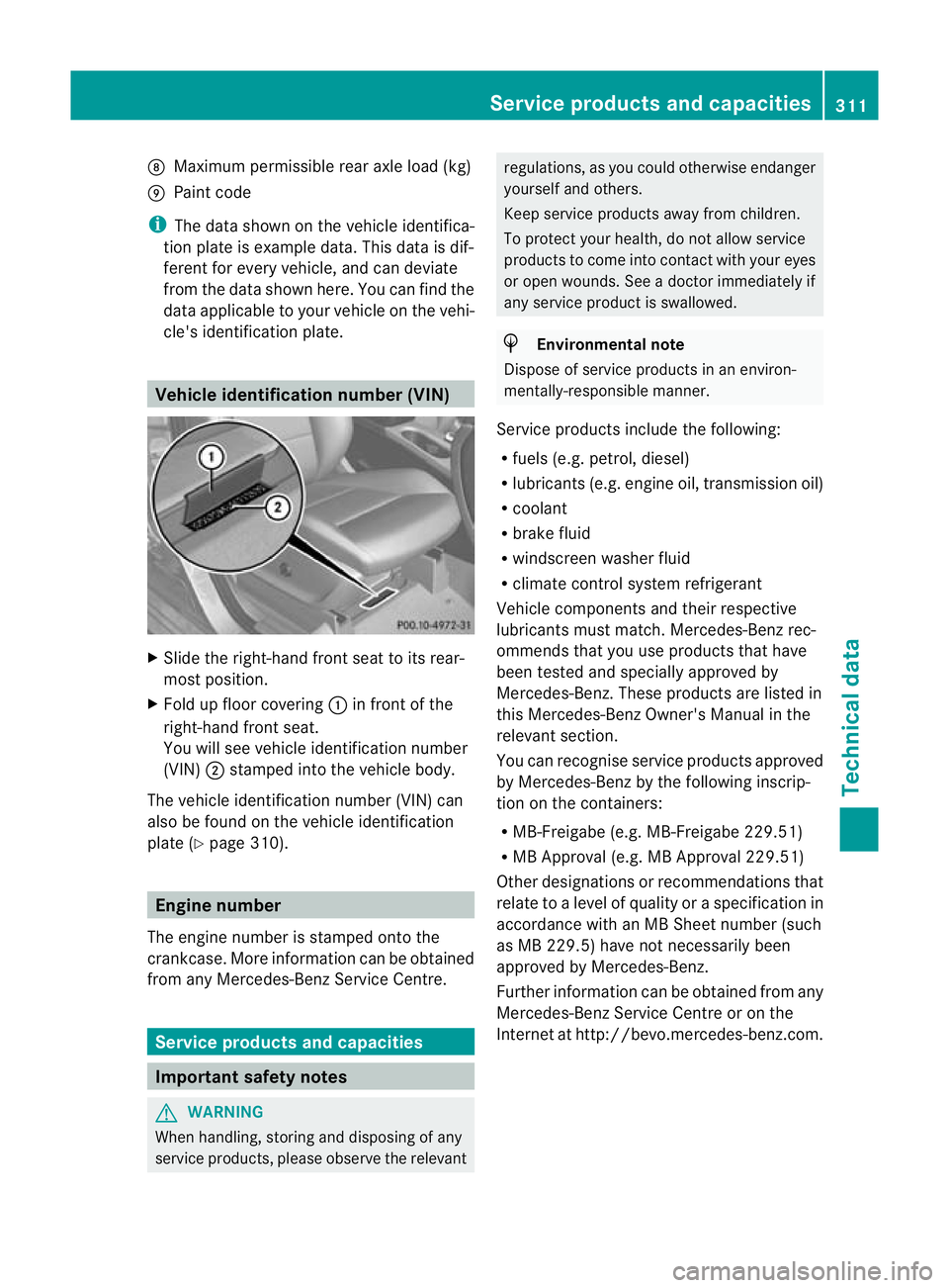
X
Slide the right-hand front seat to its rear-
most position.
X Fold up floor covering :in front of the
right-hand front seat.
You will see vehicle identification number
(VIN) ;stamped into the vehicle body.
The vehicle identification number (VIN) can
also be found on the vehicle identification
plate (Y page 310). Engine number
The engine number is stamped onto the
crankcase. More information can be obtained
from any Mercedes-Benz Service Centre. Service products and capacities
Important safety notes
G
WARNING
When handling, storing and disposing of any
service products, please observe the relevant regulations, as you could otherwise endanger
yourself and others.
Keep service products away from children.
To protect your health, do not allow service
products to come into contact with your eyes
or open wounds. See a doctor immediately if
any service product is swallowed.
H
Environmental note
Dispose of service products in an environ-
mentally-responsible manner.
Service products include the following:
R fuels (e.g. petrol, diesel)
R lubricants (e.g. engine oil, transmission oil)
R coolant
R brake fluid
R windscreen washer fluid
R climate control system refrigerant
Vehicle components and their respective
lubricants must match. Mercedes-Benz rec-
ommends that you use products that have
been tested and specially approved by
Mercedes-Benz. These products are listed in
this Mercedes-Ben zOwner's Manual in the
relevant section.
You can recognise service products approved
by Mercedes-Ben zby the following inscrip-
tion on the containers:
R MB-Freigabe (e.g. MB-Freigabe 229.51)
R MB Approval (e.g. MB Approval 229.51)
Other designations or recommendations that
relate to a level of quality or a specification in
accordance with an MB Sheet number (such
as MB 229.5) hav enot necessarily been
approved by Mercedes-Benz.
Further information can be obtained from any
Mercedes-Benz Service Centre or on the
Internet at http://bevo.mercedes-benz.com. Service products and capacities
311Technical data Z