MERCEDES-BENZ B-CLASS HATCHBACK 2015 Owners Manual
Manufacturer: MERCEDES-BENZ, Model Year: 2015, Model line: B-CLASS HATCHBACK, Model: MERCEDES-BENZ B-CLASS HATCHBACK 2015Pages: 293, PDF Size: 10.83 MB
Page 141 of 293
Energy consumption indicator
:may differ
from the indicator in the From start
From start
(Y page 176) trip computer in the Trip
Trip menu.
Displaying energy consumption and recu-
perated electric energy:
X Switch on Audio 20/COMAND Online (see
the separate operating instructions).
X To select Vehicle
Vehicle from the main function bar:
turn and press the controller.
The vehicle menu appears.
X To select Consumption
Consumption: turn and press the
controller.
Energy consumption :and recuperated
electric energy ;for the last 15 minute s of
the journey are shown.
Exiting the vehicle settings: X Press the %button on the controller.
or X To select %: slide 6and press the con-
troller.
To reset values: the values are reset From
From
start start along with the trip computer
(Y page 178).
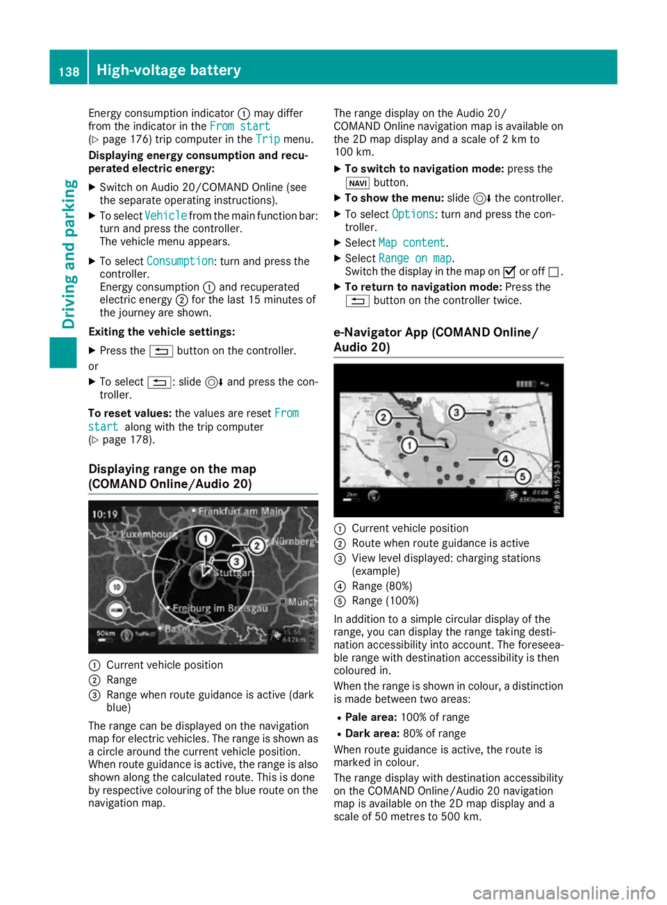
Displaying range on the map
(COMAND Online/Audio 20) :
Current vehicle position
; Range
= Range when route guidance is active (dark
blue)
The range can be displayed on the navigation
map for electric vehicles. The range is shown as
a circle around the current vehicle position.
When route guidance is active, the range is also
shown along the calculated route. This is done
by respective colouring of the blue route on the
navigation map. The range display on the Audio 20/
COMAND Online navigation map is available on
the 2D map display and a scale of 2 km to
100 km.
X To switch to navigation mode: press the
ß button.
X To show the menu: slide6the controller.
X To select Options Options: turn and press the con-
troller.
X Select Map content
Map content.
X Select Range on map
Range on map .
Switch the display in the map on Oor off ª.
X To return to navigation mode: Press the
% button on the controller twice.
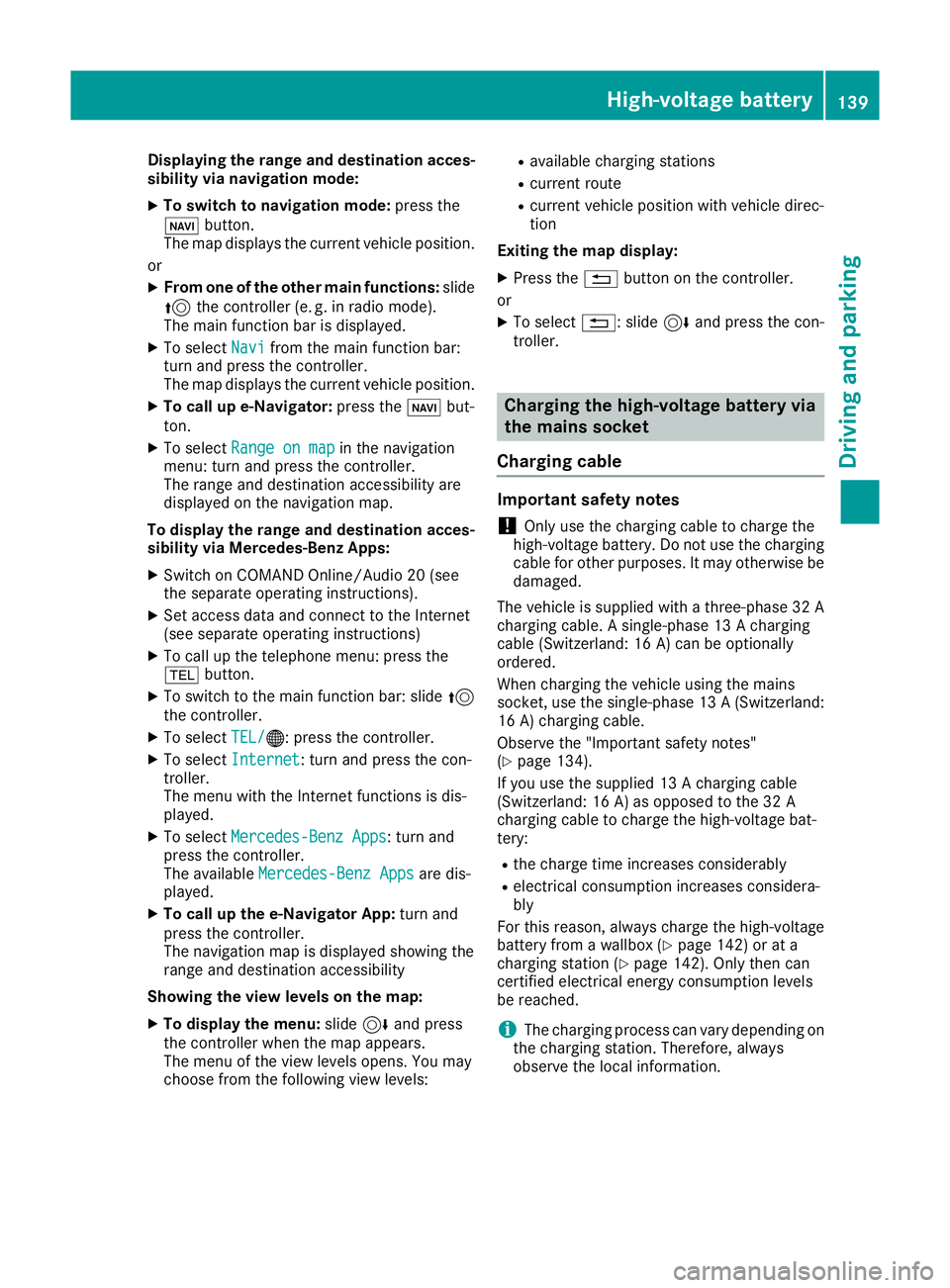
e-Navigator App (COMAND Online/
Audio 20) :
Current vehicle position
; Route when route guidance is active
= View level displayed: charging stations
(example)
? Range (80%)
A Range (100%)
In addition to a simple circular display of the
range, you can display the range taking desti-
nation accessibility into account. The foreseea-
ble range with destination accessibility is then
coloured in.
When the range is shown in colour, a distinction
is made between two areas:
R Pale area: 100% of range
R Dark area: 80% of range
When route guidance is active, the route is
marked in colour.
The range display with destination accessibility
on the COMAND Online/Audio 20 navigation
map is available on the 2D map display and a
scale of 50 metres to 500 km. 138
High-voltage batteryDriving and parking
Page 142 of 293
Displaying the range and destination acces-
sibility via navigation mode:
X To switch to navigation mode: press the
ß button.
The map displays the current vehicle position.
or
X From one of the other main functions: slide
5 the controller (e. g. in radio mode).
The main function bar is displayed.
X To select Navi
Navi from the main function bar:
turn and press the controller.
The map displays the current vehicle position.
X To call up e-Navigator: press theßbut-
ton.
X To select Range on map Range on map in the navigation
menu: turn and press the controller.
The range and destination accessibility are
displayed on the navigation map.
To display the range and destination acces-
sibility via Mercedes-Benz Apps:
X Switch on COMAND Online/Audio 20 (see
the separate operating instructions).
X Set access data and connect to the Internet
(see separate operating instructions)
X To call up the telephone menu: press the
% button.
X To switch to the main function bar: slide 5
the controller.
X To select TEL/
TEL/®: press the controller.
X To select Internet
Internet: turn and press the con-
troller.
The menu with the Internet functions is dis-
played.
X To select Mercedes-Benz Apps
Mercedes-Benz Apps: turn and
press the controller.
The available Mercedes-Benz Apps Mercedes-Benz Apps are dis-
played.
X To call up the e-Navigator App: turn and
press the controller.
The navigation map is displayed showing the
range and destination accessibility
Showing the view levels on the map:
X To display the menu: slide6and press
the controller when the map appears.
The menu of the view levels opens. You may
choose from the following view levels: R
available charging stations
R current route
R current vehicle position with vehicle direc-
tion
Exiting the map display:
X Press the %button on the controller.
or
X To select %: slide 6and press the con-
troller. Charging the high-voltage battery via
the mains socket
Charging cable Important safety notes
! Only use the charging cable to charge the
high-voltage battery. Do not use the charging
cable for other purposes. It may otherwise be damaged.
The vehicle is supplied with a three-phase 32 A
charging cable. A single-phase 13 A charging
cable (Switzerland: 16 A) can be optionally
ordered.
When charging the vehicle using the mains
socket, use the single-phase 13 A (Switzerland:
16 A) charging cable.
Observe the "Important safety notes"
(Y page 134).
If you use the supplied 13 A charging cable
(Switzerland: 16 A) as opposed to the 32 A
charging cable to charge the high-voltage bat-
tery:
R the charge time increases considerably
R electrical consumption increases considera-
bly
For this reason, always charge the high-voltage
battery from a wallbox (Y page 142) or at a
charging station (Y page 142). Only then can
certified electrical energy consumption levels
be reached.
i The charging process can vary depending on
the charging station. Therefore, always
observe the local information. High-voltage battery
139Driving and parking Z
Page 143 of 293
Stowing the charging cable
The charging cable can be stowed in a bag in the
boot of the vehicle. To do so, the bag must be
secured to the lashing eyelets using the retain-
ing strap provided.
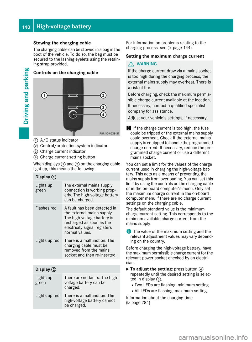
Controls on the charging cable :
A/C status indicator
; Control/protection system indicator
= Charge current indicator
? Charge current setting button
When displays :and ;on the charging cable
light up, this means the following: Display
:
: Lights up
green The external mains supply
connection is working prop-
erly. The high-voltage battery
can be charged.
Flashes red A fault has been detected in
the external mains supply.
The high-voltage battery is
recharged as soon as the
electricity signal registers
normal values.
Lights up red There is a malfunction. The
charging cable must be
removed from the mains
socket and then re-inserted.
Display
; ; Lights up
green There are no faults. The high-
voltage battery can be
charged.
Lights up red There is a malfunction. The
high-voltage battery cannot
be charged. For information on problems relating to the
charging process, see (Y
page 144).
Setting the maximum charge current G
WARNING
If the charge current draw via a mains socket is too high during the charging process, the
external mains supply may overheat. There isa risk of fire.
Before charging, check the maximum permis-
sible charge current available at the location.
If necessary, contact a qualified specialist
company for assistance.
Adjust your vehicle's settings, if necessary.
! If the charge current is too high, the fuse
could be tripped or the external mains supply could overheat. Check if the external mains
supply is equipped to handle the programmed charge current. If necessary, reduce the pro-
grammed charge current or use a different
mains socket.
You can set a limit for the values of the charge
current used in charging the high-voltage bat-
tery. This acts as a means of preventing the
mains supply from overloading. You can set this
limit by using the controls on the charging cable
or in the on-board computer's menu. Only set
the maximum charge current in the on-board
computer menu if there are no charge current
settings on the charging cable.
The default standard value is the minimum
charge current setting. This corresponds to the
minimum available charge current from the
mains supply.
i The value of the maximum setting and the
relevant adjustment values may vary depend-
ing on the country.
Before charging the high-voltage battery, have
the maximum permissible charge current for the relevant power socket checked by an electri-
cian.
X To adjust the setting: press button?
repeatedly until the desired setting is selec-
ted in display =.
R Two LEDs are flashing: minimum setting
R All LEDs are flashing: maximum setting
Information about the charging time
(Y page 284) 140
High-voltage batteryDriving and parking
Page 144 of 293
If, after the charging process, the charging cable
is:
R left connected to the power socket, the cur-
rently selected values will be used for the next
charging process.
R removed from the power socket, the values
will be reset to the minimum setting for the
next charging process. You may then need to reset the values of the maximum charge cur-
rent.
If the charge current values that have been set
on the charging cable and the on-board com-
puter are different, the high-voltage battery is
charged using the lower value.
If the vehicle requires more time than usual to
charge the high-voltage battery, check:
R the settings of the maximum charge current
on the controls of the charging cable
R the settings of the maximum charge current in
the menu of the on-board computer
Indicator lamps on the vehicle socket When the indicator lamps on the vehicle socket
light up, this means the following: Left indicator lamp
Ì Ì Lights up The charging cable can be
connected or removed.
Flashes The charging cable connector
has been connected incor-
rectly. Right indicator lamp
Ý ÝFlashes
slowly in
orange The connection between the
vehicle and the current
source is being established
before charging begins.
Flashes
slowly in
green The high-voltage battery is
charging.
Lights up
green The high-voltage battery is
fully charged.
Flashes rap-
idly in red A malfunction has occurred
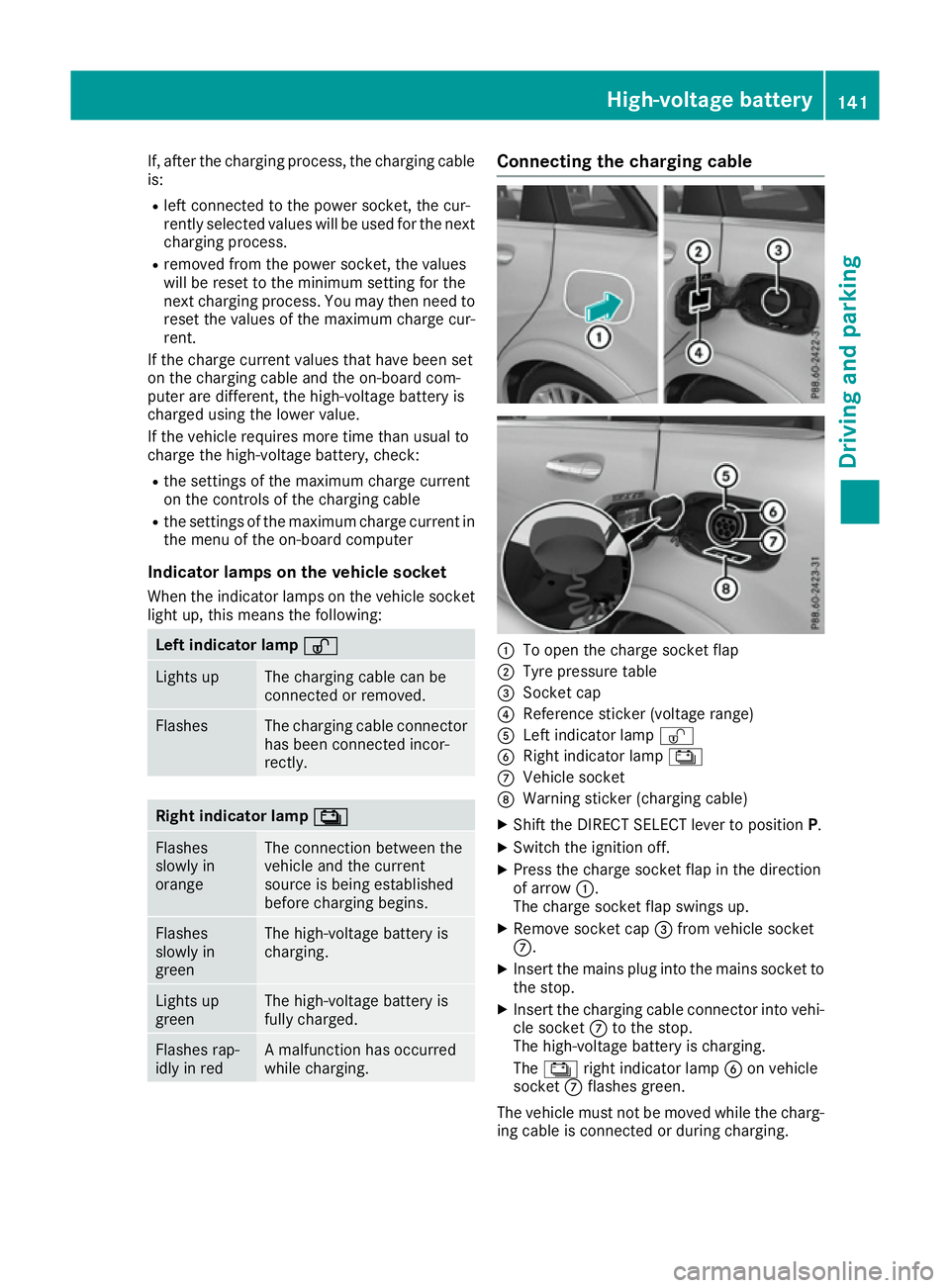
while charging. Connecting the charging cable
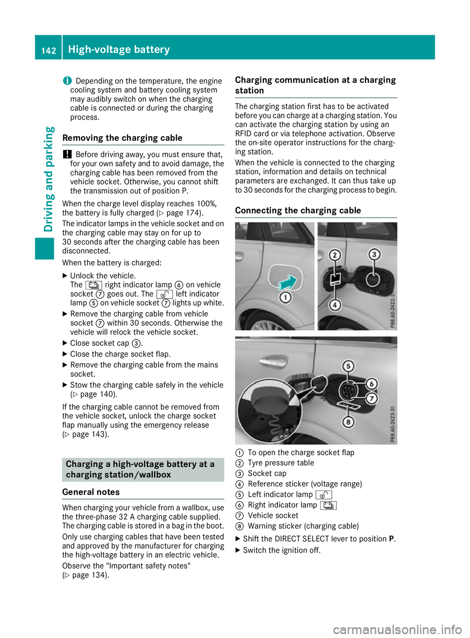
:
To open the charge socket flap
; Tyre pressure table
= Socket cap
? Reference sticker (voltage range)
A Left indicator lamp Ì
B Right indicator lamp Ý
C Vehicle socket
D Warning sticker (charging cable)
X Shift the DIRECT SELECT lever to position P.
X Switch the ignition off.
X Press the charge socket flap in the direction
of arrow :.
The charge socket flap swings up.
X Remove socket cap =from vehicle socket
C.
X Insert the mains plug into the mains socket to
the stop.
X Insert the charging cable connector into vehi-
cle socket Cto the stop.
The high-voltage battery is charging.
The Ý right indicator lamp Bon vehicle
socket Cflashes green.
The vehicle must not be moved while the charg- ing cable is connected or during charging. High-voltage battery
141Driving and parking Z
Page 145 of 293
i
Depending on the temperature, the engine
cooling system and battery cooling system
may audibly switch on when the charging
cable is connected or during the charging
process.
Removing the charging cable !
Before driving away, you must ensure that,
for your own safety and to avoid damage, the charging cable has been removed from the
vehicle socket. Otherwise, you cannot shift
the transmission out of position P.
When the charge level display reaches 100%,
the battery is fully charged (Y page 174).
The indicator lamps in the vehicle socket and on the charging cable may stay on for up to
30 seconds after the charging cable has been
disconnected.
When the battery is charged:
X Unlock the vehicle.
The Ý right indicator lamp Bon vehicle
socket Cgoes out. The Ìleft indicator
lamp Aon vehicle socket Clights up white.
X Remove the charging cable from vehicle
socket Cwithin 30 second s. Otherwise the
vehicle will relock the vehicle socket.
X Close socket cap =.
X Close the charge socket flap.
X Remove the charging cable from the mains
socket.
X Stow the charging cable safely in the vehicle
(Y page 140).
If the charging cable cannot be removed from
the vehicle socket, unlock the charge socket
flap manually using the emergency release
(Y page 143). Charging a high-voltage battery at a
charging station/wallbox
General notes When charging your vehicle from a wallbox, use
the three-phase 32 A charging cable supplied.
The charging cable is stored in a bag in the boot.
Only use charging cables that have been tested
and approved by the manufacturer for charging
the high-voltage battery in an electric vehicle.
Observe the "Important safety notes"
(Y page 134). Charging communication at a charging
station The charging station first has to be activated
before you can charge at a charging station. You
can activate the charging station by using an
RFID card or via telephone activation. Observe
the on-site operator instructions for the charg-
ing station.
When the vehicle is connected to the charging
station, information and details on technical
parameters are exchanged. It can thus take up
to 30 seconds for the charging process to begin.
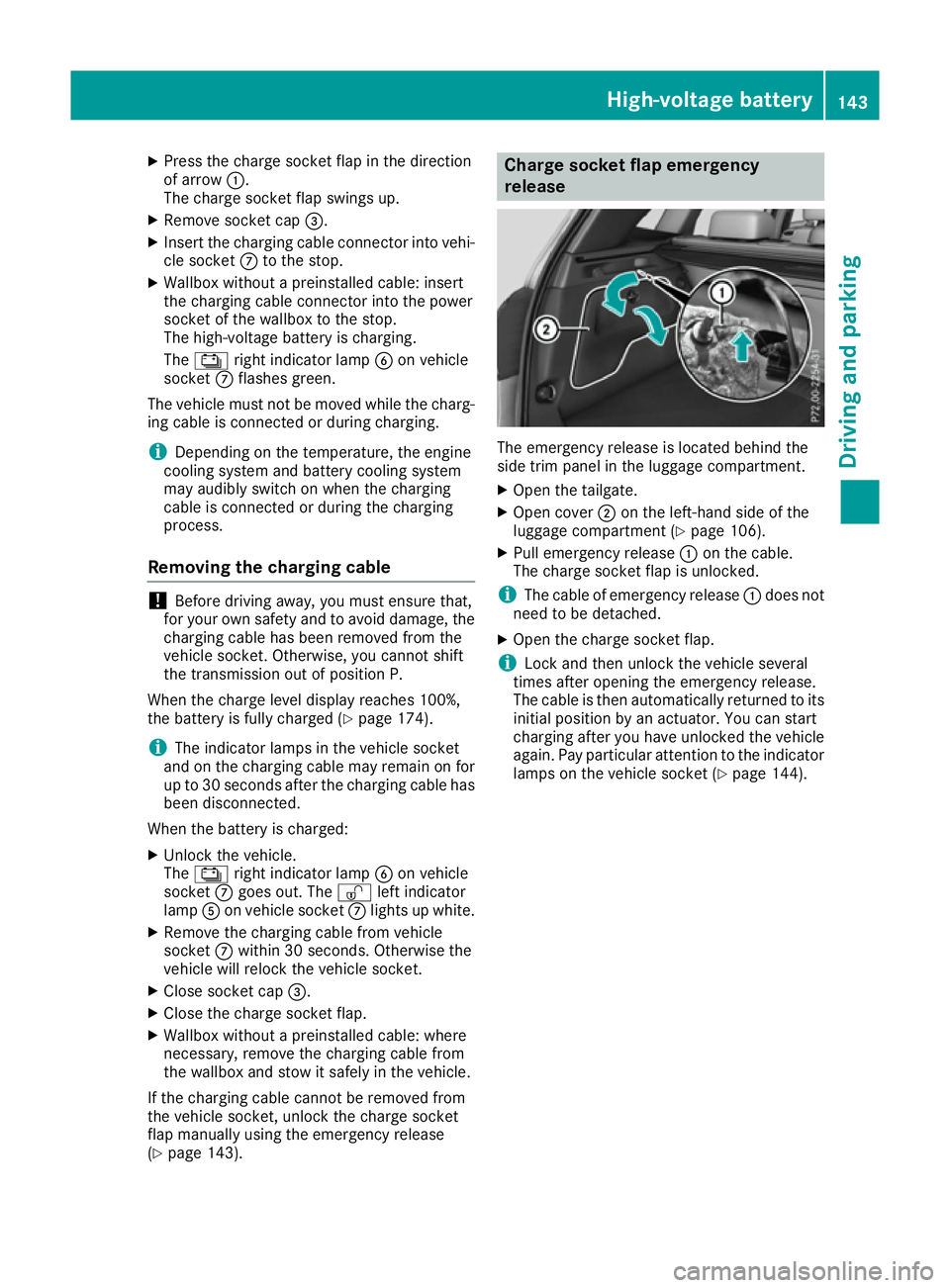
Connecting the charging cable :
To open the charge socket flap
; Tyre pressure table
= Socket cap
? Reference sticker (voltage range)
A Left indicator lamp Ì
B Right indicator lamp Ý
C Vehicle socket
D Warning sticker (charging cable)
X Shift the DIRECT SELECT lever to position P.
X Switch the ignition off. 142
High-voltage batteryDriving and parking
Page 146 of 293
X
Press the charge socket flap in the direction
of arrow :.
The charge socket flap swings up.
X Remove socket cap =.
X Insert the charging cable connector into vehi-
cle socket Cto the stop.
X Wallbox without a preinstalled cable: insert
the charging cable connector into the power
socket of the wallbox to the stop.
The high-voltage battery is charging.
The Ý right indicator lamp Bon vehicle
socket Cflashes green.
The vehicle must not be moved while the charg-
ing cable is connected or during charging.
i Depending on the temperature, the engine
cooling system and battery cooling system
may audibly switch on when the charging
cable is connected or during the charging
process.
Removing the charging cable !
Before driving away, you must ensure that,
for your own safety and to avoid damage, the
charging cable has been removed from the
vehicle socket. Otherwise, you cannot shift
the transmission out of position P.
When the charge level display reaches 100%,
the battery is fully charged (Y page 174).
i The indicator lamps in the vehicle socket
and on the charging cable may remain on for
up to 30 seconds after the charging cable has
been disconnected.
When the battery is charged: X Unlock the vehicle.
The Ý right indicator lamp Bon vehicle
socket Cgoes out. The Ìleft indicator
lamp Aon vehicle socket Clights up white.
X Remove the charging cable from vehicle
socket Cwithin 30 seconds. Otherwise the
vehicle will relock the vehicle socket.
X Close socket cap =.
X Close the charge socket flap.
X Wallbox without a preinstalled cable: where
necessary, remove the charging cable from
the wallbox and stow it safely in the vehicle.
If the charging cable cannot be removed from
the vehicle socket, unlock the charge socket
flap manually using the emergency release
(Y page 143). Charge socket flap emergency
release
The emergency release is located behind the
side trim panel in the luggage compartment.
X
Open the tailgate.
X Open cover ;on the left-hand side of the
luggage compartment (Y page 106).
X Pull emergency release :on the cable.
The charge socket flap is unlocked.
i The cable of emergency release
:does not
need to be detached.
X Open the charge socket flap.
i Lock and then unlock the vehicle several
times after opening the emergency release.
The cable is then automatically returned to its
initial position by an actuator. You can start
charging after you have unlocked the vehicle
again. Pay particular attention to the indicator lamps on the vehicle socket (Y page 144). High-voltage battery
143Driving and parking Z
Page 147 of 293
Problems with the charging process
Problem
Possible causes/consequences and
M
MSolutions The charge socket flap
cannot be opened. The charge socket flap is not unlocked.
X Unlock the vehicle (Y page 72). The key batteries are discharged.
X Unlock the vehicle manually using the key (Y page 73). The charge socket flap is unlocked, but the opening mechanism is
jammed.
X Lock and unlock the vehicle.
If, after that, the opening mechanism is still jammed:
X Manually unlock the charge socket flap using the emergency
release (Y page 143).
X Consult a qualified specialist workshop. The charging cable can-
not be inserted into the
vehicle socket. The vehicle socket is locked.
X
Ensure that the selector lever is in position P.The high-voltage battery
is not being charged. The
Ý indicator lamp on
the vehicle socket
flashes red. A malfunction has occurred during the initialisation of the charging
process.
X Ensure that the charging cable is connected to the mains socket.
X Remove the charging cable connector from the vehicle socket and
wait 30 seconds; then re-insert it into the vehicle socket.
X If the problem persists, consult a qualified specialist workshop. The high-voltage battery
is not charged during the
charging process when
connected to a mains
socket. The Ýindica-
tor lamp on the vehicle
socket does not light up
after the charging cable
connector has been
inserted into the vehicle
socket. The mains socket is faulty.
X Have the mains socket checked to test if it is functioning properly.
or X Use a different mains socket. The charging cable con-
nector cannot be
removed from the vehi-
cle socket. The charging cable connector has not been unlocked.
X Press button %on the key. The charging cable connector on the
vehicle socket is unlocked.
X Remove the charging cable connector from the vehicle socket. The charging cable connector is blocked.
X Manually unlock the charge socket flap using the emergency
release (Y page 143).
X Consult a qualified specialist workshop. 144
High-voltage batteryDriving and parking
Page 148 of 293
Parking
Important safety notes
G
WARNING
If you release the parking brake on uphill or
downhill gradients, the vehicle can begin to
move when in park position P. There is a risk
of an accident.
To avoid hazardous situations:
R prevent the parked vehicle from rolling on
uphill or downhill gradients by always
applying the parking brake.
R do not park the vehicle on uphill or downhill
gradients if the parking brake is malfunc-
tioning. G
WARNING
If you leave children unattended in the vehi-
cle, they may be able to set the vehicle in
motion, for example, if they:
R release the parking brake
R shift the transmission out of park position P
R start the vehicle's drive system
In addition, they may operate vehicle equip-
ment. There is a risk of an accident and injury.
When leaving the vehicle, always take the key
with you and lock the vehicle. Never leave
children unattended in the vehicle.
! while the vehicle is rolling, do not shift the
transmission directly from Dto R, from Rto D
or directly to P.
Do not open the driver's door while the vehi-
cle is in motion. Otherwise, at low speeds in
transmission position Dor R, park position P
is engaged automatically and the electrical
parking brake is applied.
The transmission could be damaged.
! Always secure the vehicle correctly against
rolling away. Otherwise, the vehicle or its driv-
etrain could be damaged.
To ensure that the vehicle is safeguarded
against rolling away unintentionally: R the electric parking brake must be applied.
R the transmission must be in position P.R
the key must be turned to position 0in the
ignition lock and then removed from the igni-
tion lock or the Start/Stop button must be
pressed
R on uphill or downhill gradients, turn the front
wheels towards the kerb. Switching off the drive system
G
WARNING
If you switch off the ignition while the vehicle
is in motion, safety-relevant functions are
restricted or not available. This can affect the power steering function and the brake boost-
ing effect, for example. You will then require
considerably more force to steer and brake.
There is a risk of an accident.
Do not switch off the ignition while the vehicle is in motion.
X Shift the DIRECT SELECT lever to position P.
X With the key: turn the key to position 0in the
ignition lock and remove it.
The immobiliser is activated.
X With the Start/Stop button: press the
Start/Stop button (Y page 126).
The drive system and all the indicator lamps in
the instrument cluster go out.
When the driver's door is closed, this corre-
sponds to key position 1. When the driver's
door is open, this corresponds to key position
0: "key removed".
If you switch the drive system off with the trans- mission in position Ror D, the transmission
automatically shifts to N.
With the key: if you then open the driver's door
or the front-passenger door or remove the key
from the ignition, the transmission automati-
cally shifts to P.
With the Start/Stop button: if you then open
the driver's door or the front-passenger door,
the transmission automatically shifts to P.
If you want the transmission to remain in neutral
N, e.g. when having the vehicle cleaned in an
automatic car wash with a towing system: Parking
145Driving and parking Z
Page 149 of 293
With the key:
X Switch the ignition on.
X Depress the brake pedal and keep it
depressed.
X Shift to neutral N.
X Release the brake pedal.
X Release the electric parking brake.
X Switch off the ignition and leave the key in the
ignition lock.
With the Start/Stop button:
X Remove the Start/Stop button from the igni-
tion lock.
X Insert the key into the ignition lock.
X Switch the ignition on.
X Depress the brake pedal and keep it
depressed.
X Shift to neutral N.
X Release the brake pedal.
X Release the electric parking brake.
X Switch off the ignition and leave the key in the
ignition lock. Electric parking brake
General notes G
WARNING
If you leave children unattended in the vehi-
cle, they may be able to set the vehicle in
motion, for example, if they:
R release the parking brake
R shift the transmission out of park position P
R start the vehicle's drive system
In addition, they may operate vehicle equip-
ment. There is a risk of an accident and injury.
When leaving the vehicle, always take the key
with you and lock the vehicle. Never leave
children unattended in the vehicle. The function of the electric parking brake and
the parking lock is dependent on the on-board
voltage. If the on-board voltage is low or if there
is a malfunction in the system, it may not be
possible to apply the released parking brake or
to shift the transmission to the Pposition.
X If this is the case, only park the vehicle on
level ground and secure it to prevent it from
rolling away.
X Shift the transmission to position P.
It may not be possible to release an applied
parking brake if the on-board voltage is low or if
there is a malfunction in the system. Contact a
qualified specialist workshop.
The electric parking brake carries out a function check at regular intervals when the drive system
is switched off. Noises that occur are normal.
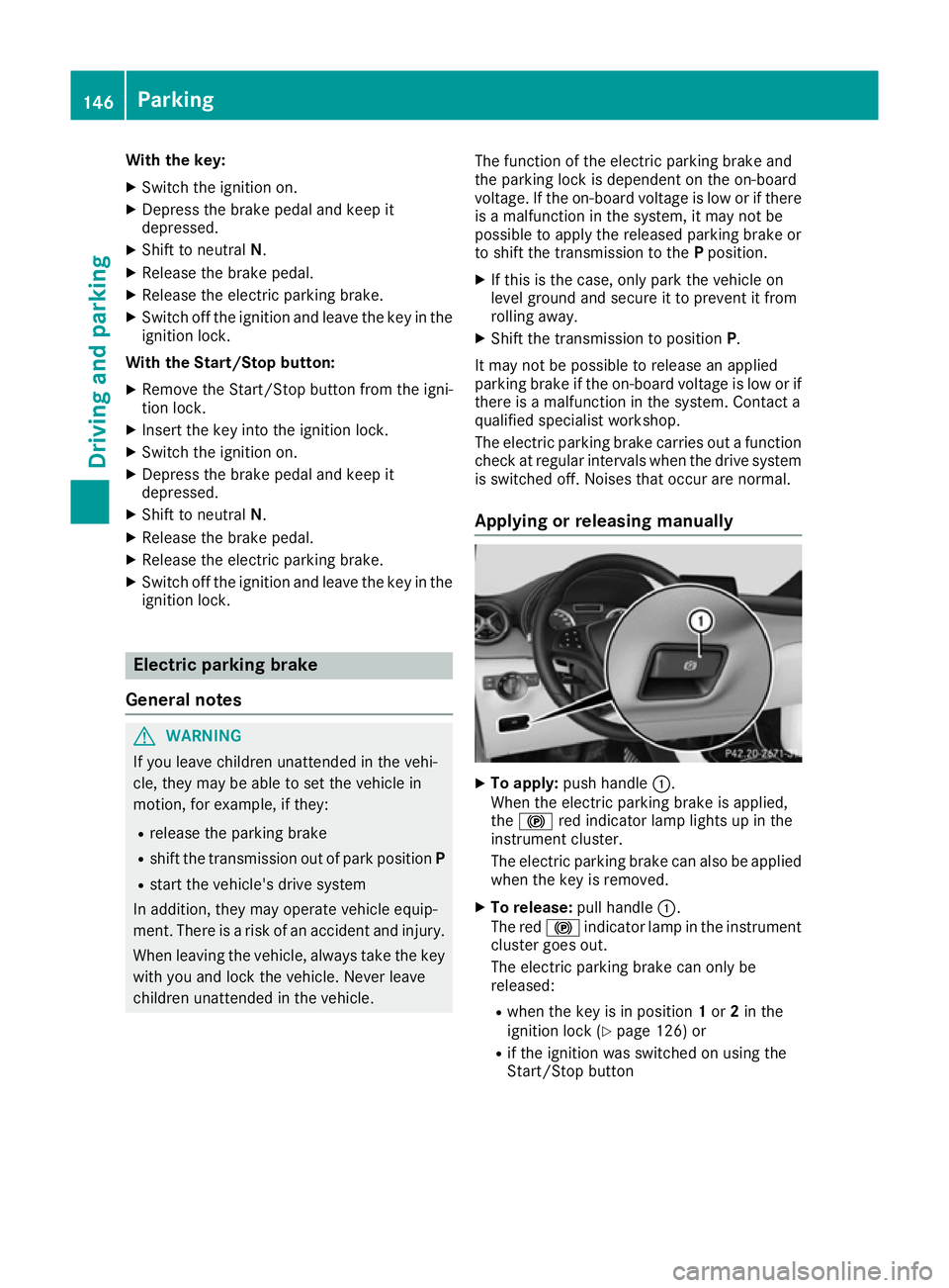
Applying or releasing manually X
To apply: push handle :.
When the electric parking brake is applied,
the ! red indicator lamp lights up in the
instrument cluster.
The electric parking brake can also be applied
when the key is removed.
X To release: pull handle:.
The red !indicator lamp in the instrument
cluster goes out.
The electric parking brake can only be
released:
R when the key is in position 1or 2in the
ignition lock (Y page 126) or
R if the ignition was switched on using the
Start/Stop button 146
ParkingDriving and parking
Page 150 of 293
Applying automatically
When the vehicle's HOLD function is holding the
vehicle at a standstill, the electric parking brake is engaged automatically.
In addition, at least one of the following condi-
tions must be fulfilled:
R the drive system is switched off
R the driver's door is open and the seat belt is
not fastened
R there is a system malfunction
R the power supply is insufficient
R the vehicle is stationary for a lengthy period
The red !indicator lamp in the instrument
cluster lights up.
Releasing automatically The electric parking brake of your vehicle is
released automatically when all of the following
conditions are fulfilled:
R the vehicle has been started
R the transmission is in position Dor R
R the seat belt is fastened
R you depress the accelerator pedal
If the transmission is in position R, the tailgate
must be closed.
If your seat belt is not fastened, the following
conditions must be fulfilled to automatically
release the electric parking brake:
R the driver's door is closed
R you have shifted out of transmission position
P or you have previously driven faster than
3 km/h
Ensure that you do not depress the accelerator
pedal unintentionally. Otherwise, the parking
brake will be released and the vehicle will start
to move.
Emergency braking The vehicle can also be braked during an emer-
gency by using the electric parking brake.
X While driving, push handle :of the electric
parking brake (Y page 146).
The vehicle is braked as long as you keep
handle :of the electric parking brake
pressed. The longer the electric parking brake
handle :is depressed, the greater the brak-
ing force. During braking:
R a warning tone sounds
R the Release parking brake
Release parking brake message
appears
R the red !indicator lamp in the instrument
cluster flashes
When the vehicle has been braked to a stand-
still, the electric parking brake is applied. Parking up the vehicle
If you leave the vehicle parked up for longer than
four weeks, the battery may be damaged by
exhaustive discharging.
If you leave the vehicle parked up for longer than
six weeks, it may suffer from lack of use.
X Visit a qualified specialist workshop and seek
advice.
i You can obtain information about trickle
chargers from a qualified specialist work-
shop. Driving tips
General notes
Important safety notes G
WARNING
If you switch off the ignition while driving,
safety-relevant functions are only available
with limitations, or not at all. This could affect, for example, the power steering and the brake
boosting effect. You will require considerably
more effort to steer and brake. There is a risk of an accident.
Do not switch off the ignition while driving.
Your vehicle is powered by an electric motor.
The electric motor draws the energy required to
drive the vehicle from the high-voltage battery.
When braking and rolling, kinetic energy is con- verted into electrical energy by energy recovery
and stored in the high-voltage battery.
The range of the vehicle is reduced when con-
sumers are switched on, e.g. THERMOTRONIC. Driving tips
147Driving and pa rking Z