MERCEDES-BENZ B-CLASS SPORTS 2014 Owners Manual
Manufacturer: MERCEDES-BENZ, Model Year: 2014, Model line: B-CLASS SPORTS, Model: MERCEDES-BENZ B-CLASS SPORTS 2014Pages: 360, PDF Size: 39.45 MB
Page 261 of 360
Cargo net
Important safety notes G
WARNING
On its own ,the cargo ne tcanno tsecure or
restrain heav yobjects, items of luggag eand
heav yloads .You could be hit by an unsecured
load during sudden changes in direction,
braking or in the event of an accident .There
is an increased risk of injury or even fatal
injury.
Always store object ssothat they cannot be
flung around. Secure objects, luggage or
loads against slipping or tipping over, e.g. by
using tie downs, even if you are using the
cargo net.
It is important to use acargo net if you load
the vehicle with small object sabove the seat
backrests. For safety reasons, always use a
cargo net when transporting loads.
The cargo net is located in the stowage space
under the cargo compartment floor
(Y page 259).
X Open both Velcro fastener sand remove the
cargo net.
X Unroll and unfol dthe cargo net.
The joints on the uppe rand lowe rguide rod
should engage audibly.
The corresponding cargo ti edown rings for
tightening th ecargo ne tare in th ecargo
compartmen t(Ypage 257).
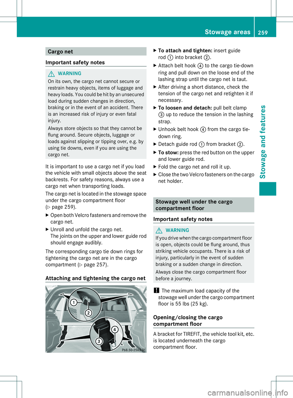
Attaching and tightening th ecargo net X
To attach and tighten: insert guide
rod 001Aintob racket 0010.
X Attac hbelt hook 0021to th ecargo tie-down
rin ga nd pull down on th eloose end of the
lashing strap until the cargo net is taut.
X After driving ashort distance, check the
tension of the cargo net and retighten it if
necessary.
X To loosen and detach: pull belt clamp
0023 up to reduce the tension in the lashing
strap.
X Unhook belt hook 0021from the cargo tie-
down ring.
X Detach guide rod 001Afrom bracket 0010.
X To stow: press the red button on the upper
and lower guide rod.
X Fold the cargo net and roll it up.
X Close the two Velcro fastener sonthe cargo
net holder. Stowage well under the cargo
compartment floor
Important safety notes G
WARNING
If you drive when the cargo compartment floor
is open, object scould be flung around, thus
striking vehicle occupants. There is arisk of
injury, particularly in the event of sudden
braking or asudden change in direction.
Always close the cargo compartment floor
before ajourney.
! The maximum load capacity of the
stowage well under the cargo compartment
floor is 55 lbs (25 kg).
Opening/closing the cargo
compartment floor Ab
racket for TIREFIT, the vehicl etool kit, etc.
is located underneath the cargo
compartment floor. Stowage areas
259Stowage and features Z
Page 262 of 360
X
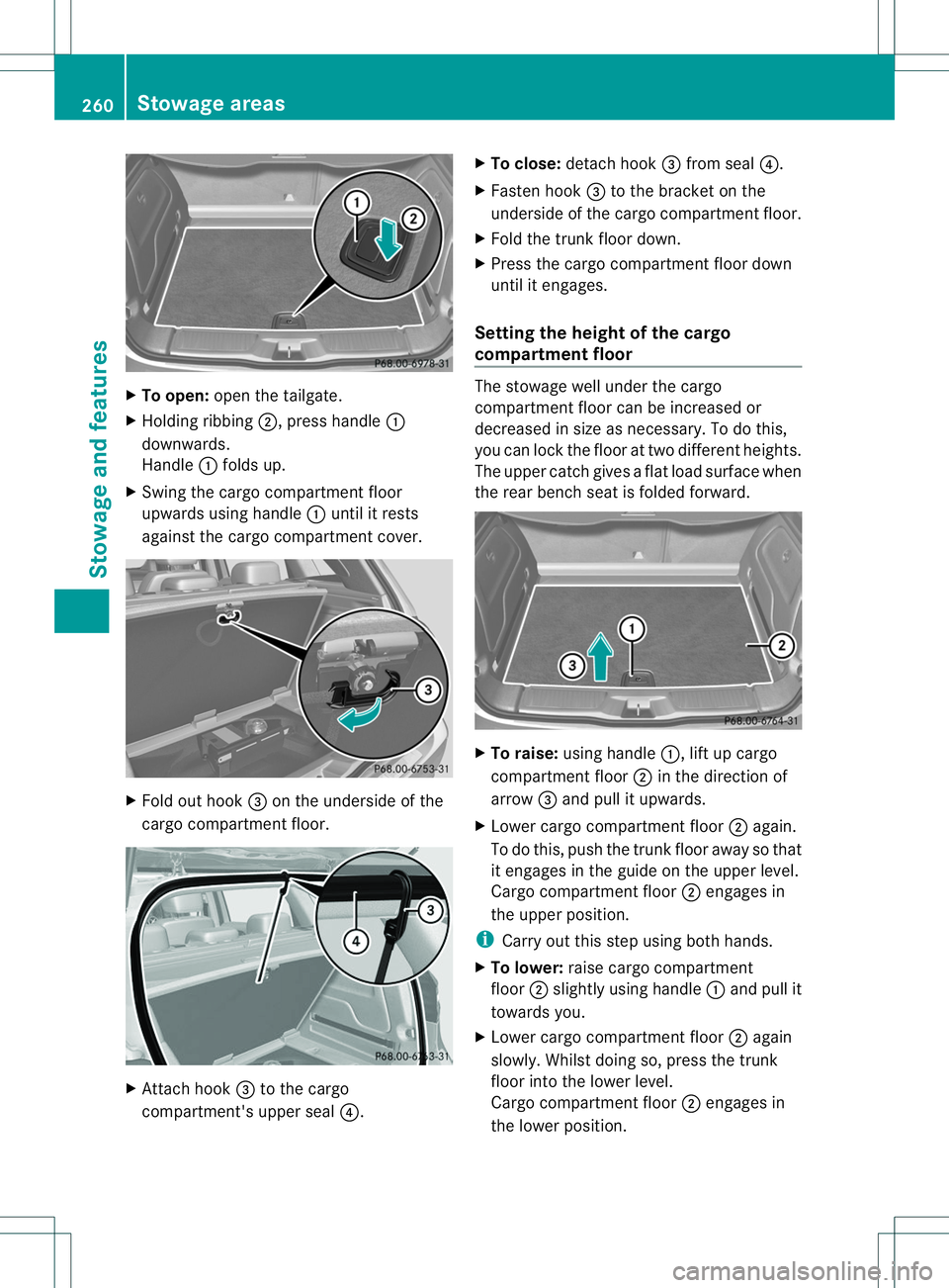
To open: open the tailgate.
X Holding ribbing 0010,press handle 001A
downwards.
Handle 001Afolds up.
X Swing the cargo compartment floor
upwards using handle 001Aunti litr ests
against the cargo compartment cover. X
Fol do ut hook 0023on th eunderside of the
cargo compartment floor. X
Attach hook 0023to the cargo
compartment's upper seal 0021.X
To close: detach hook 0023from seal 0021.
X Fasten hook 0023to the bracket on the
underside of the cargo compartment floor.
X Fold the trunk floor down.
X Press the cargo compartment floor down
until it engages.
Setting the height of the cargo
compartment floor The stowage well under the cargo
compartment floor can be increased or
decreased in size as necessary. To do this,
you can lock the floor at two different heights.
The upper catchg
ivesaflat load surface when
the rear bench seat is folded forward. X
To raise: using handle 001A,lift up cargo
compartment floor 0010in the direction of
arrow 0023and pull it upwards.
X Lower cargo compartment floor 0010again.
To do this, push the trunk floor away so that
it engages in the guide on the upper level.
Cargo compartment floor 0010engages in
the upper position.
i Carry out this step using both hands.
X To lower: raise cargo compartment
floor 0010slightly using handle 001Aand pull it
towards you.
X Lower cargo compartment floor 0010again
slowly. Whilst doing so, press the trunk
floor into the lower level.
Cargo compartment floor 0010engages in
the lower position. 260
Stowage areasStowage and features
Page 263 of 360
Roo
fcarrier
Important safety notes G
WARNING
Whe nyou load the roof, the center of gravity
of the vehicle rises and the driving
characteristics change. If you exceed the
maximum roof load, the driving
characteristics, as well as steering and
braking, will be greatly impaired. There is a
risk of an accident.
Never exceed the maximum roof load and
adjust your driving style.
! Mercedes-Benz recommends that you
only use roof carriers that have been tested
and approved for Mercedes-Benz vehicles.
This helps to prevent damage to the
vehicle.
Position the load on the roof rack in such a
way that the vehicle will not sustain
damage even when it is in motion.
Ensure that, depending on the vehicle's
equipment, you can raise the panorama
roof with power tilt/sliding panel fully and
open the tailgate fully when the roof carrier
is installed.
The maximum roof load is 165 lbs((75 kg).
An incorrectly secured roof carrier or roof
load may become detached from the vehicle.
You must therefor eensure that you observe
the roof carrier manufacturer' sinstallation
instructions.
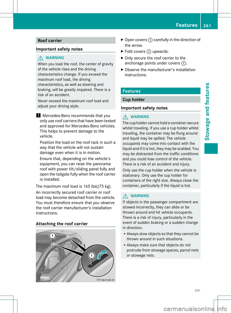
Attaching the roof carrier X
Open covers 001Acarefully in the direction of
the arrow.
X Fold covers 001Aupwards.
X Only secure the roof carrier to the
anchorage points under covers 001A.
X Observe the manufacturer' sinstallation
instructions. Features
Cu
ph older
Important safety notes G
WARNING
The cup holde rcannot hold acontainer secure
whilst traveling. If you use acup holde rwhilst
traveling, the container may be flung around
and liquidm ay be spilled. The vehicle
occupants may come into contact with the
liquida nd if it is hot, they may be scalded. You
may be distracted from the traffic conditions
and you could lose control of the vehicle.
There is arisk of an accident and injury.
Only use the cup holder when the vehicle is
stationary. Only use the cup holder for
containers of the right size. Always close the
container, particularly if the liquidish ot. G
WARNING
If objectsint he passenger compartmenta re
stowed incorrectly, they can slide or be
thrown around and hit vehicle occupants.
There is arisk of injury, particularly in the
event of sudden braking or asudden change
in direction.
R Always stow objectssot hat they cannot be
thrown around in such situations.
R Always make sure that objectsdon ot
protrude from stowage spaces, parcel nets
or stowage nets. Features
261Stowage and features
Z
Page 264 of 360
R
Close th elockable stowage spaces while
driving.
R Stow and secure object sthata re heavy,
hard ,pointy, sharp-edged ,fra gile or too
large in th ecargo compartment.
! Only use th ecup holders for containers of
th er igh tsize and which have lids. The
drinks could otherwise spill.
The stowage compartments in the doors
provide space for bottles:
R front :capacity up to 51 fl. oz. (1. 5l)
R rear: capacity up to 17 fl. oz. (0. 5l)
Cup holder in th efront-compartment
center console The cup holder and the rubber mat
underneat
hcan be removed for cleaning.
Clean the mwith clean ,lukewarm water only. X
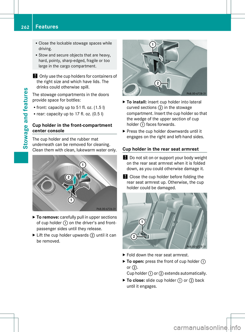
To remove: carefully pull in upper sections
of cup holder 001Aon the driver's and front-
passenger sides until the yrelease.
X Lift the cup holder upwards 0010until it can
be removed. X
To install: insert cup holder int olateral
curved sections 0010in the stowage
compartment. Insert the cup holder so that
the wedge of the upper section of cup
holder 001Aface sforwards.
X Press the cup holder downwards until it
engages on the right and left-han dsides.
Cup holder in th erears eat armrest !
Do not sit on or support your body weight
on the rear seat armrest when it is folded
down, as you could otherwise damage it.
! Close the cup holder befor efoldin gthe
rear seat armrest up. Otherwise ,the cup
holder could be damaged. X
Fold down the rear seat armrest.
X To open: press the front of cup holder 001A
or 0010.
Cup holder 001Aor0010 extends automatically.
X To close: slide cup holder 001Aor0010 back
until it engages. 262
FeaturesStowage and features
Page 265 of 360
Sun visors
Overview G
WARNING
If the mirror cover of the vanity mirror is folded
up when the vehicle is in motion, you could be
blinded by incident light. There is arisk of an
accident.
Always keep the mirror cover folded down
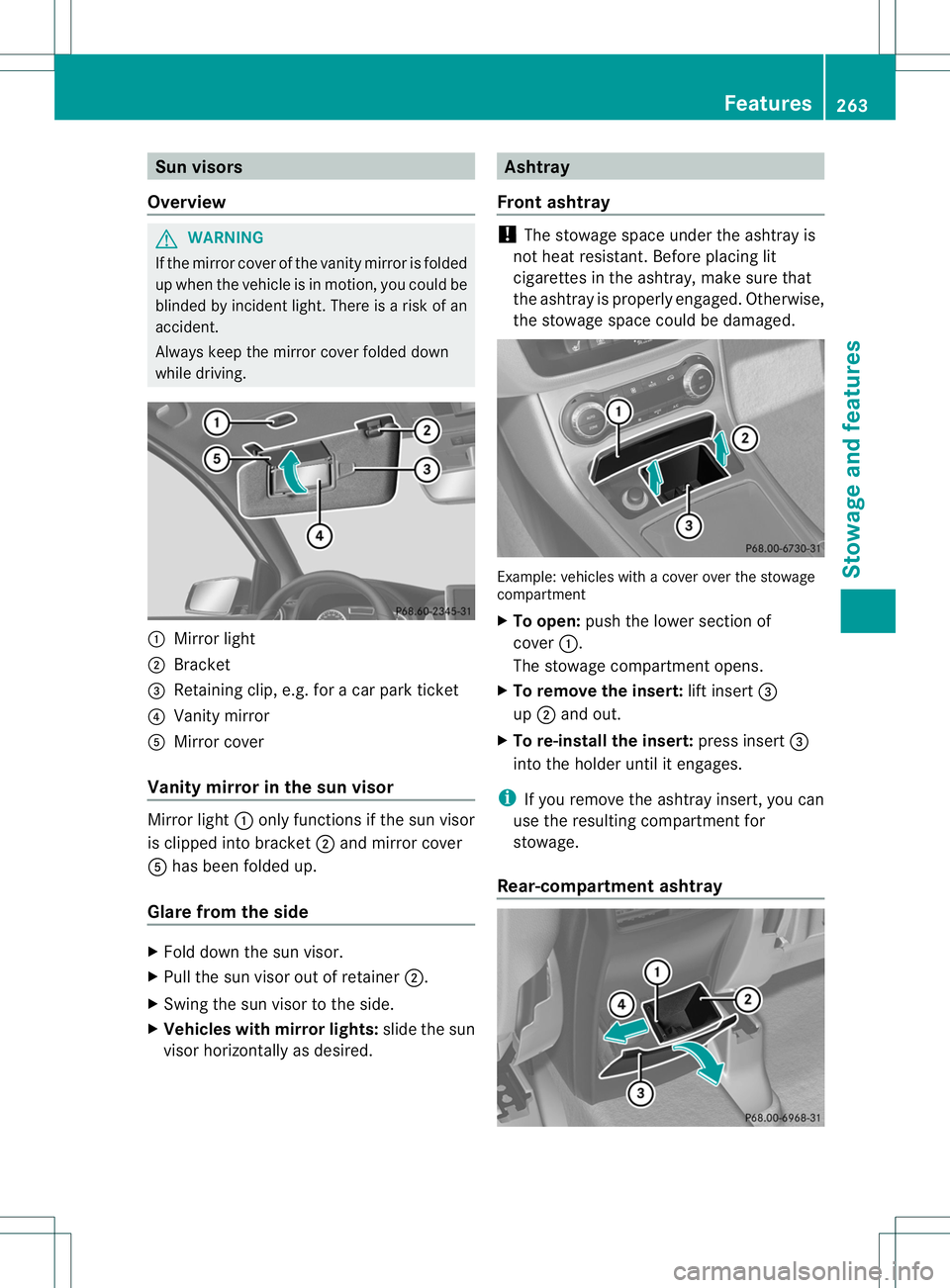
while driving. 001A
Mirror light
0010 Bracket
0023 Retaining clip, e.g. for acar park ticket
0021 Vanity mirror
001E Mirror cover
Vanity mirror in the sun visor Mirror light
001Aonly functions if the sun visor
is clipped into bracket 0010and mirror cover
001E has been folded up.
Glare from the side X
Fold down the sun visor.
X Pull the sun visor out of retainer 0010.
X Swing the sun visor to the side.
X Vehicles with mirror lights: slide the sun
visor horizontally as desired. Ashtray
Front ashtray !
The stowage space under the ashtray is
not heat resistant .Before placing lit
cigarettes in the ashtray, make sure that
the ashtray is properly engaged. Otherwise,
the stowage space could be damaged. Example: vehicles with
acover over the stowage
compartment
X To open: push the lower section of
cover 001A.
The stowage compartment opens.
X To remove the insert: lift insert0023
up 0010 and out.
X To re-install the insert: press insert0023
intot he holder until it engages.
i If you remove the ashtray insert ,you can
use the resultin gcompartment for
stowage.
Rear-compartment ashtray Features
263Stowage and features Z
Page 266 of 360
X
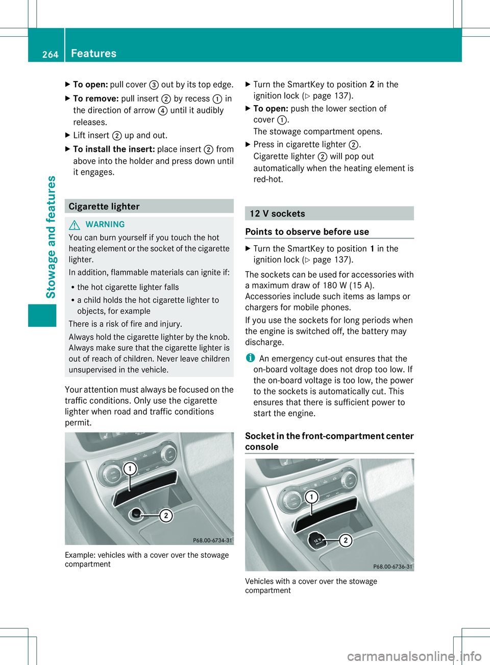
To open: pull cover 0023outbyi tstope dge.
X To remove: pull insert0010by recess 001Ain
th ed irection of arrow 0021until it audibly
releases.
X Lif tins ert 0010up and out.
X To install th einsert: placeinsert 0010from
abov eintot he holder and press down until
it engages. Cigarett
elighter G
WARNING
You can burn yoursel fifyou touch the hot
heating element or the socket of the cigarette
lighter.
In addition, flammable materials can ignite if:
R the hot cigarett elighter falls
R ac hild holds the hot cigarett elighter to
objects, for example
There is arisk of fire and injury.
Always hold the cigarett elighter by the knob.
Always make sure that the cigarett elighter is
out of reach of children. Never leave children
unsupervised in the vehicle.
Your attention must always be focused on the
traffic conditions. Only use the cigarette
lighter when road and traffic conditions
permit. Example: vehicles with
acover over the stowage
compartment X
Turn the SmartKey to position 2in the
ignition lock (Y page 137).
X To open: push the lower section of
cover 001A.
The stowage compartment opens.
X Press in cigarett elighter 0010.
Cigarette lighter 0010will pop out
automatically when the heating element is
red-hot. 12
Vsockets
Point stoo bserve befor euse X
Turn th eSmartKey to position 1in the
ignitio nlock (Y page 137).
The socket scan be used for accessories with
am aximum draw of 180 W(15 A).
Accessories include such items as lamps or
chargers for mobile phones.
If you use the socket sfor long periods when
the engine is switched off, the battery may
discharge.
i An emergenc ycut-out ensures that the
on-board voltage does not drop too low. If
the on-board voltage is too low, the power
to the socket sisautomatically cut. This
ensures that there is sufficient power to
start the engine.
Socket in the front-compartment center
console Vehicles with
acover over the stowage
compartment 264
FeaturesStowage and features
Page 267 of 360
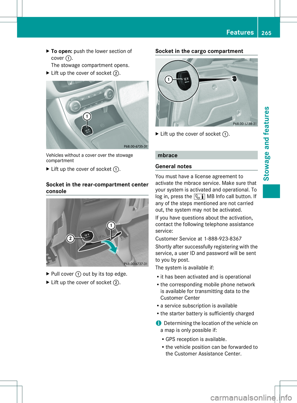
X
To open: push the lowe rsection of
cover 001A.
The stowage compartment opens.
X Lift up the cover of socket 0010.Vehicles without
acover over the stowage
compartment
X Lift up the cover of socket 001A.
Socket in the rear-compartment center
console X
Pull cover 001Aout by its top edge.
X Lift up the cover of socket 0010.Socket in the cargo compartment X
Lift up the cover of socket 001A. mbrace
General notes You must have
alicense agreement to
activat ethe mbrace service. Make sure that
your system is activated and operational. To
log in, press the 001FMB Infoc all button.If
any of the steps mentioned are not carried
out, the system may not be activated.
If you have questions about the activation,
contact the following telephon eassistance
service:
Customer Service at 1-888-923-8367
Shortly after successfully registering with the
service, auser ID and password will be sent
to you by post.
The system is available if:
R it has been activated and is operational
R the correspondin gmobile phone network
is available for transmitting data to the
Customer Center
R as ervic esubscription is available
R the starter batter yissufficiently charged
i Determinin gthe location of the vehicle on
am ap is only possible if:
R GPS reception is available.
R the vehicle position can be forwarded to
the Customer Assistance Center. Features
265Stowage and features Z
Page 268 of 360
The mbrac
esystem To adjus
tthe volume during acall, proceed
as follows:
X Press the 0008or0009 button on the
multifunction steering wheel.
or
X Use the volume controller of the audio
system/COMAND.
The system offers various services, e.g:
R Automatic and manual emergency call
R Roadside Assistancec all
R MB Info call
System self-test After you have switched on the ignition, the
system carries out aself-diagnosis.
Am alfunction in th esystem has been
detected if on eofthefollowin goccurs:
R The indicator lamp in th eSOS bu tton does
no tc om eond uringthe system self-test.
R The indicator lamp in the 0014Roadside
Assistanc ebutto ndoes not light up during
self-diagnosis of the system.
R The indicator lamp in the 001FMB Info call
button does not light up during self-
diagnosis of the system.
R The indicator lamp in one or more of the
following button scontinues to light up red
after the system self-diagnosis:
- SOS button
- 0014 Roadside Assistance call button
- 001F MB Info call button
R After the system self-diagnosis, the
Inoperative or
Service Not Activated message appears in the
multifunction display.
If am alfunction is indicated as outlined
above, the system may not operate as
expected. In the event of an emergency, help
will have to be summoned by other means. Have the system checked at the nearest
authorized Mercedes-Benz Center or call the
following telephone assistance service:
Customer Servic
eat1-888-923-8367
Emergency call Important safety notes
G
WARNING
It can be dangerous to remain in the vehicle,
even if you have pressed the SOS button in an
emergenc yif:
R you see smoke inside or outside of the
vehicle, e.g. if there is afire after an
accident
R the vehicle is on adangerous section of
road
R the vehicle is not visible or cannot easily be
seen by other road users, particularly when
dark or in poor visibility conditions
There is arisk of an accident and injury.
Leave the vehicle immediately in this or
similar situations as soon as it is safe to do
so. Move to asafe location along with other
vehicle occupants. In such situations, secure
the vehicle in accordanc ewith national
regulations, e. g. with awarning triangle.
You must have alicense agreement to
activate the mbrace service. Make sure that
your system is activated and operational. To
register, press the 001FMB Info call button.
If any of the steps mentioned are not carried
out, the system may not be activated.
If you have questions about the activation,
contact the following telephone assistance
service:
Customer Servic eat1-888-923-8367
General notes
An emergenc ycall is dialed automatically if
an air bag or Emergency Tensionin gDevice is
triggered.
i You cannot end an automatically
triggered emergenc ycall yourself. 266
FeaturesStowage and features
Page 269 of 360
An emergency cal
lcan also be initiated
manually.
As soo nasthe emergency call has been
initiated, the indicator lamp in the SOS button
flashes. The multifunction displays hows the
Connecting Call message.
The audioo utput is muted.
Once the connection has been made, the
Call Connected message appears in the
multifunction display.
All important information on the emergency
is transmitted, for example:
R Current location of the vehicle (as
determined by the GPS system)
R Vehicle identification number
R Information on the severity of the accident
Shortly after the emergency call has been
initiated, avoice connection is automatically
established between the Customer
Assistance Center and the vehicle occupants.
R If the vehicle occupants respond, the
Mercedes-Benz Customer Assistance
Center attempts to get more information
on the emergency.
R If there is no response from the vehicle
occupants, an ambulance is immediately
sent to the vehicle.
If no voice connection can be established to
the Mercedes-Benz Customer Assistance
Center, the system has been unable to initiate
an emergency call.
This can occur, for example, if the relevant
mobile phone network is not available. The
indicator lamp in the SOS button flashes
continuously.
The Call Failed message appears in the
multifunction displaya nd must be confirmed.
In this case, summon assistance by other
means. Making an emergency call
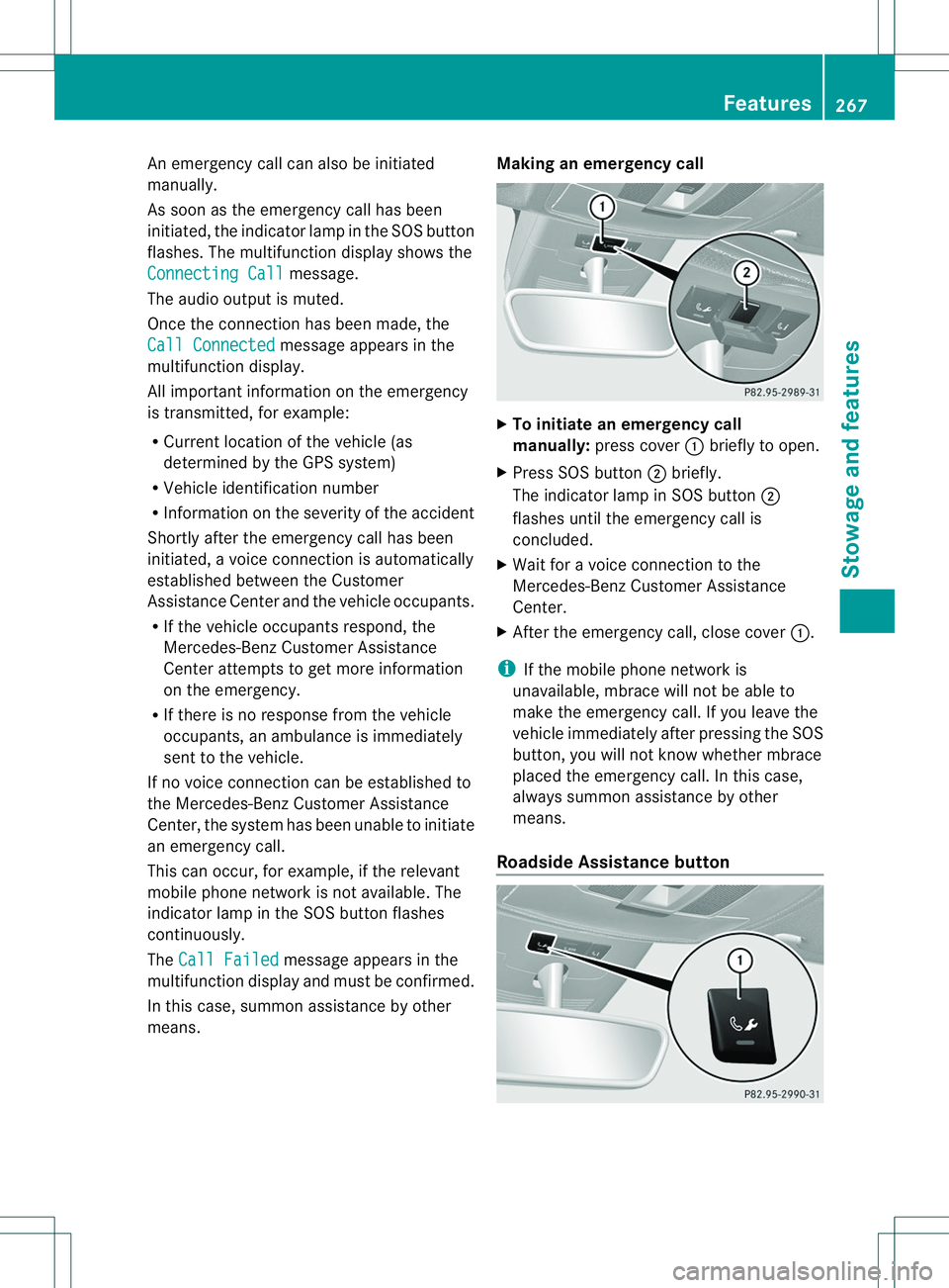
X
To initiate an emergency call
manually: press cover 001Abriefly to open.
X Press SOS button 0010briefly.
The indicator lamp in SOS button 0010
flashes until the emergency call is
concluded.
X Wait for avoice connection to the
Mercedes-Benz Customer Assistance
Center.
X After the emergency call, close cover 001A.
i If the mobile phone network is
unavailable, mbrace will not be able to
make the emergency call. If you leave the
vehicle immediately after pressing the SOS
button, you will not know whether mbrace
placed the emergency call. In this case,
always summon assistance by other
means.
Roadside Assistance button Features
267Stowage and features Z
Page 270 of 360
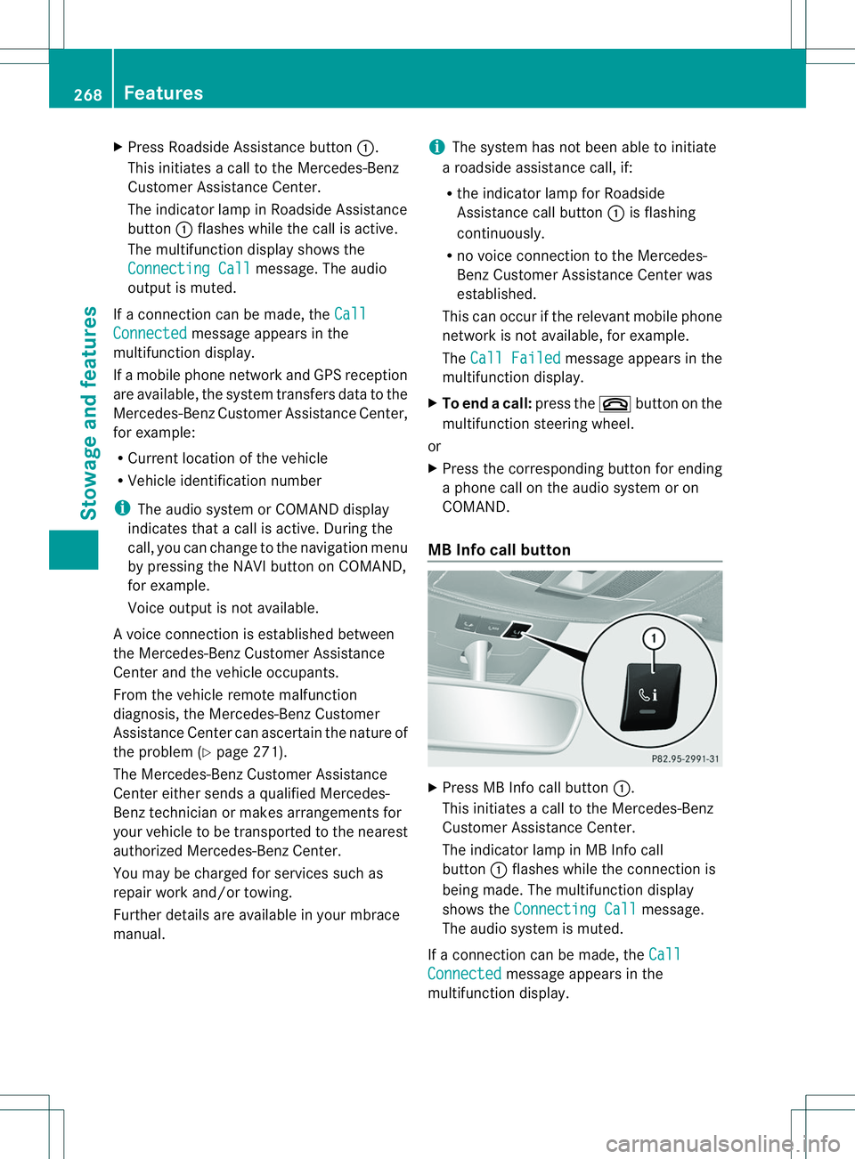
X
Press Roadside Assistance button 001A.
This initiates acall to the Mercedes-Benz
Customer Assistance Center.
The indicator lamp in Roadside Assistance
button 001Aflashes while the call is active.
The multifunction display shows the
Connectin gCall message. The audio
output is muted.
If ac onnection can be made, the CallConnected message appears in the
multifunction display.
If am obile phone network and GPS reception
are available, the system transfers data to the
Mercedes-Benz Customer Assistance Center,
for example:
R Current location of the vehicle
R Vehicle identification number
i The audio system or COMAND display
indicates that acall is active. During the
call, you can change to the navigation menu
by pressing the NAVI button on COMAND,
for example.
Voice output is not available.
Av oice connection is established between
the Mercedes-Benz Customer Assistance
Center and the vehicle occupants.
From the vehicle remote malfunction
diagnosis, the Mercedes-Benz Customer
Assistance Center can ascertain the nature of
the problem (Y page 271).
The Mercedes-Benz Customer Assistance
Center either sends aqualified Mercedes-
Benz technician or makes arrangement sfor
your vehicle to be transported to the nearest
authorized Mercedes-Benz Center.
You may be charged for services such as
repair work and/or towing.
Further details are available in your mbrace
manual. i
The system has not been able to initiate
ar oadside assistance call, if:
R the indicator lamp for Roadside
Assistance call button 001Ais flashing
continuously.
R no voice connection to the Mercedes-
Benz Customer Assistance Center was
established.
This can occur if the relevant mobile phone
network is not available, for example.
The Call Failed message appears in the
multifunction display.
X To end acall: press the 0008button on the
multifunctio nsteering wheel.
or
X Press the corresponding button for ending
ap hone cal lonthe audi osystemoron
COMAND.
MB Info call button X
Press MB Info call button 001A.
This initiate sacall to th eMercedes-Benz
Custome rAssistance Center.
The indicator lamp in MB Info call
button 001Aflashes while the connection is
being made. The multifunction display
shows the Connecting Call message.
The audios ystem is muted.
If ac onnection can be made, the Call Connected message appears in the
multifunction display. 268
FeaturesStowage and features