MERCEDES-BENZ C-CLASS ESTATE 2014 Owners Manual
Manufacturer: MERCEDES-BENZ, Model Year: 2014, Model line: C-CLASS ESTATE, Model: MERCEDES-BENZ C-CLASS ESTATE 2014Pages: 489, PDF Size: 15.08 MB
Page 291 of 489
level. When driving in mountainous areas,
note that the power output of the engine,
and consequently the vehicle's gradient-
climbing capability, decrease with increas-
ing altitude. Folding out the ball coupling
G
WARNING
If the ball coupling is not correctly engaged,
the trailer can detach. There is a risk of an
accident.
Always engage the ball coupling as described. G
WARNING
If you release the ball coupling or it does not
engage correctly when folding in, it will swing out. Within pivoting range of the ball coupling,
there is an increased risk of an accident and
injury.
Only release the ball coupling if the pivoting
range is unobstructed. Always make sure that the ball coupling engages when folding in.
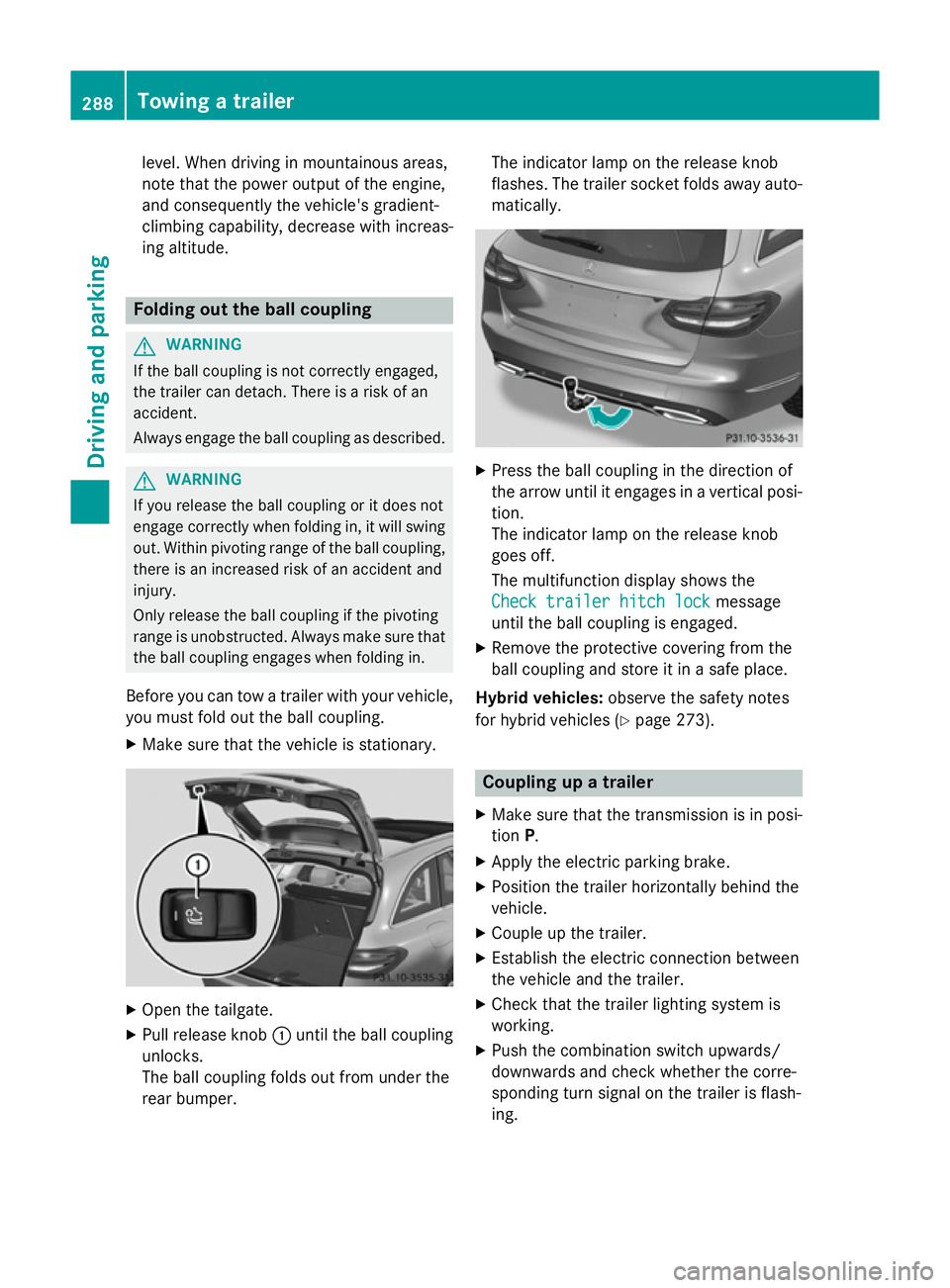
Before you can tow a trailer with your vehicle, you must fold out the ball coupling.
X Make sure that the vehicle is stationary. X
Open the tailgate.
X Pull release knob :until the ball coupling
unlocks.
The ball coupling folds out from under the
rear bumper. The indicator lamp on the release knob
flashes. The trailer socket folds away auto- matically. X
Press the ball coupling in the direction of
the arrow until it engages in a vertical posi-
tion.
The indicator lamp on the release knob
goes off.
The multifunction display shows the
Check trailer hitch lock Check trailer hitch lock message
until the ball coupling is engaged.
X Remove the protective covering from the
ball coupling and store it in a safe place.
Hybrid vehicles: observe the safety notes
for hybrid vehicles (Y page 273). Coupling up a trailer
X Make sure that the transmission is in posi-
tion P.
X Apply the electric parking brake.
X Position the trailer horizontally behind the
vehicle.
X Couple up the trailer.
X Establish the electric connection between
the vehicle and the trailer.
X Check that the trailer lighting system is
working.
X Push the combination switch upwards/
downwards and check whether the corre-
sponding turn signal on the trailer is flash-
ing. 288
Towing a trailerDriving and parking
Page 292 of 489
A connected trailer is only recognised when
the electrical connection is established
correctly and when the lighting system is
working properly. The functioning of other
systems, e.g. ESP ®
, PARKTRONIC, Active
Parking Assist, Active Blind Spot Assist or
Lane Keeping Assist also depends on this. Uncoupling a trailer
G
WARNING
If you uncouple a trailer with an engaged over- run brake, you could trap your hand between
the vehicle and the trailer drawbar. This poses a risk of injury.
Do not uncouple a trailer with an engaged
overrun brake. G
WARNING
Vehicles with level control:
If you disconnect the trailer cable, the vehicle is lowered. This can cause you or others to
become trapped between the vehicle body
and tyres, or underneath the vehicle. This
poses a risk of injury.
Make sure that no-one is in the immediate
vicinity of the wheel arch or underneath the
vehicle when disconnecting the trailer cable.
! Do not disconnect a trailer with an
engaged overrun brake. Otherwise, your
vehicle could be damaged by the rebound- ing of the overrun brake.
! Remove the installed adapter cable
before folding in the ball coupling. Other-
wise, damage may occur to the rear
bumper and the adapter cable.
X Make sure that the transmission is in posi-
tion P.
X Apply the electric parking brake.
X Secure the trailer against rolling away.
X Remove the trailer cable and decouple the
trailer. Folding in the ball coupling
G
WARNING
If you release the ball coupling or it does not
engage correctly when folding in, it will swing out. Within pivoting range of the ball coupling,
there is an increased risk of an accident and
injury.
Only release the ball coupling if the pivoting
range is unobstructed. Always make sure that the ball coupling engages when folding in.
Fold the ball coupling back in if you are not
using the trailer tow hitch. X Make sure that the vehicle is stationary and
the trailer cables are disconnected.
X Place the protective covering on the ball
coupling.
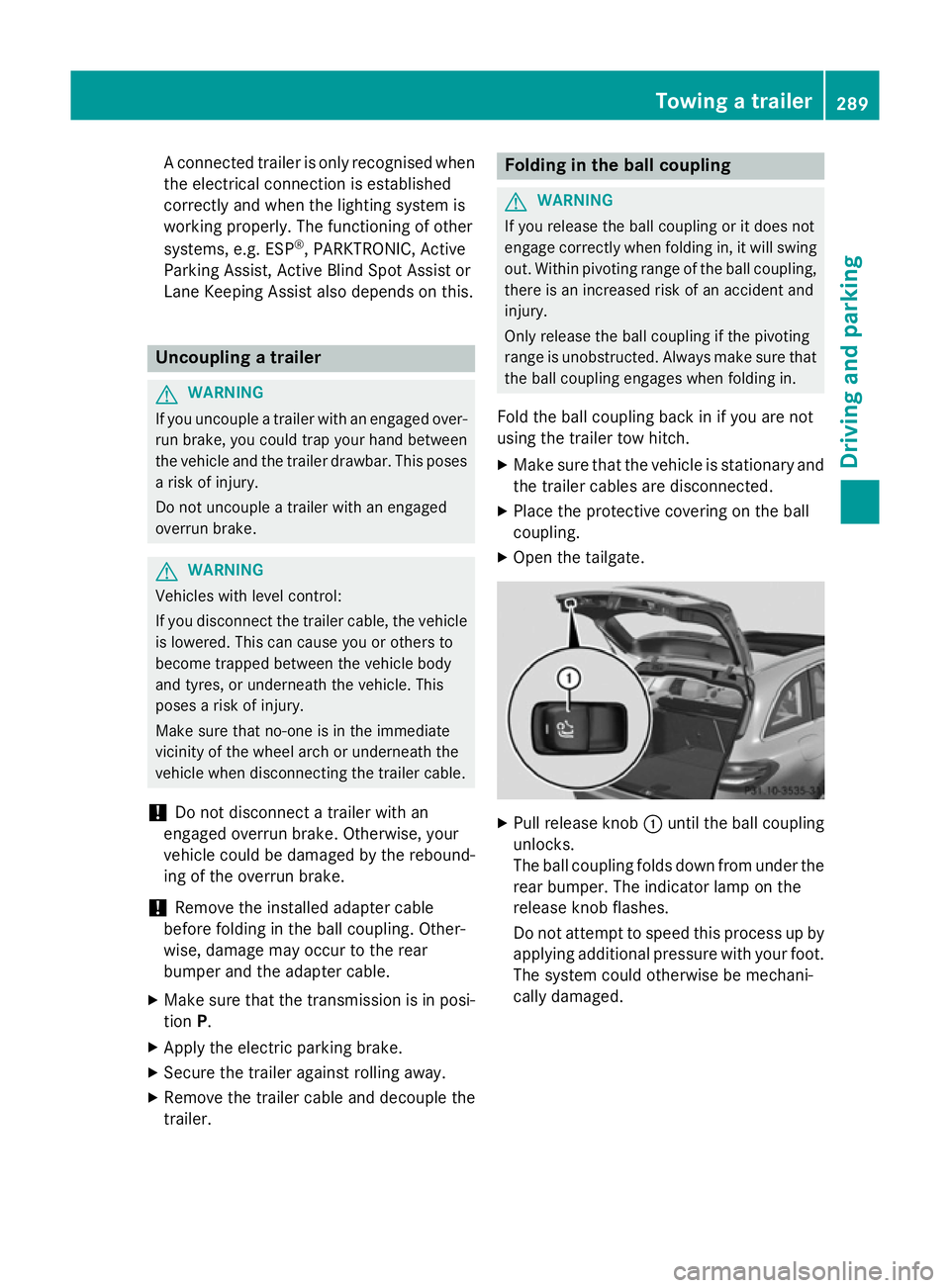
X Open the tailgate. X
Pull release knob :until the ball coupling
unlocks.
The ball coupling folds down from under the rear bumper. The indicator lamp on the
release knob flashes.
Do not attempt to speed this process up by
applying additional pressure with your foot. The system could otherwise be mechani-
cally damaged. Towing a trailer
289Driving and parking Z
Page 293 of 489
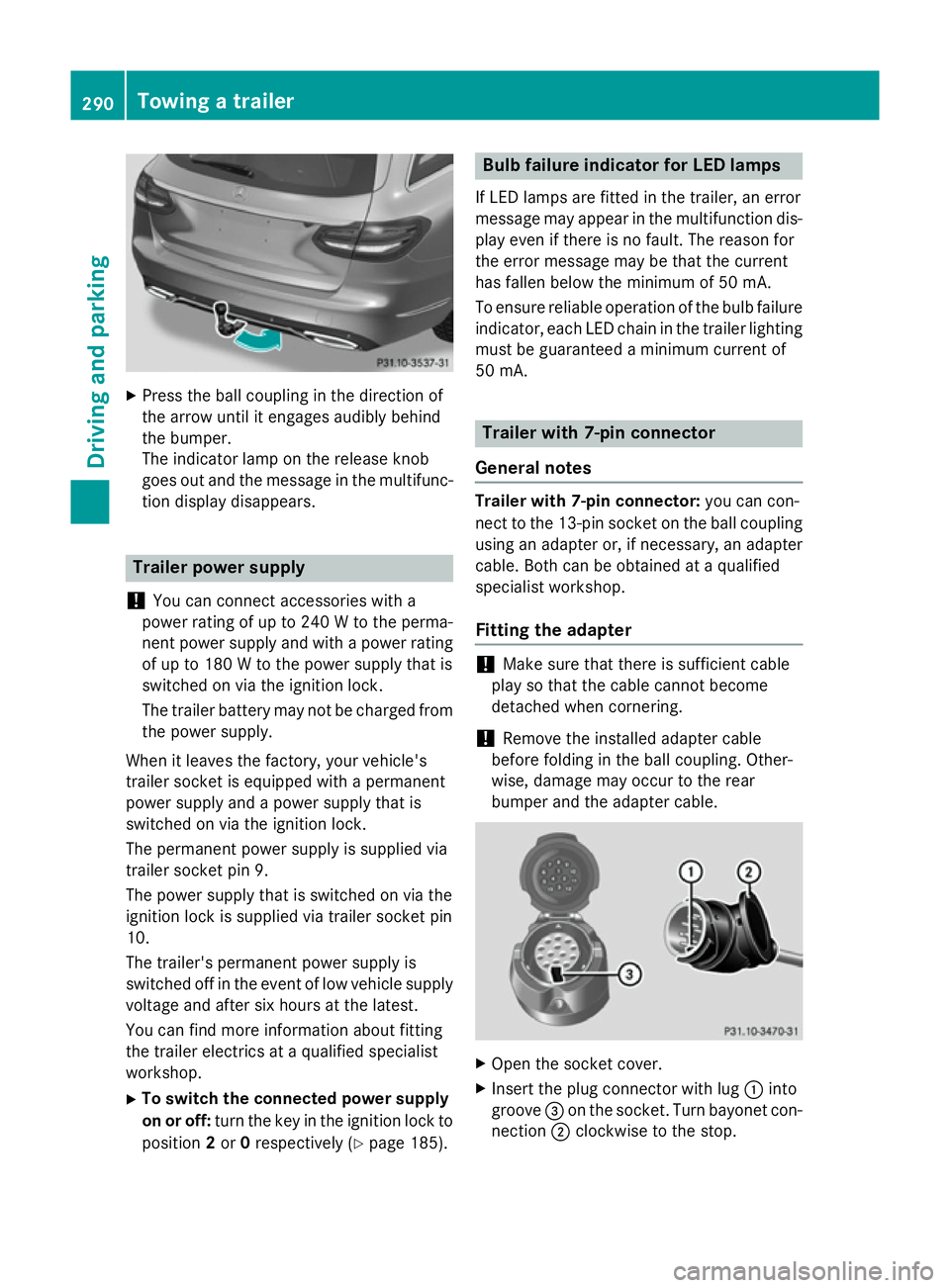
X
Press the ball coupling in the direction of
the arrow until it engages audibly behind
the bumper.
The indicator lamp on the release knob
goes out and the message in the multifunc-
tion display disappears. Trailer power supply
! You can connect accessories with a
power rating of up to 240 W to the perma-
nent power supply and with a power rating of up to 180 W to the power supply that is
switched on via the ignition lock.
The trailer battery may not be charged from the power supply.
When it leaves the factory, your vehicle's
trailer socket is equipped with a permanent
power supply and a power supply that is
switched on via the ignition lock.
The permanent power supply is supplied via
trailer socket pin 9.
The power supply that is switched on via the
ignition lock is supplied via trailer socket pin
10.
The trailer's permanent power supply is
switched off in the event of low vehicle supply
voltage and after six hours at the latest.
You can find more information about fitting
the trailer electrics at a qualified specialist
workshop.
X To switch the connected power supply
on or off: turn the key in the ignition lock to
position 2or 0respectively (Y page 185). Bulb failure indicator for LED lamps
If LED lamps are fitted in the trailer, an error
message may appear in the multifunction dis-
play even if there is no fault. The reason for
the error message may be that the current
has fallen below the minimum of 50 mA.
To ensure reliable operation of the bulb failure indicator, each LED chain in the trailer lighting
must be guaranteed a minimum current of
50 mA. Trailer with 7-pin connector
General notes Trailer with 7-pin connector:
you can con-
nect to the 13-pin socket on the ball coupling
using an adapter or, if necessary, an adapter
cable. Both can be obtained at a qualified
specialist workshop.
Fitting the adapter !
Make sure that there is sufficient cable
play so that the cable cannot become
detached when cornering.
! Remove the installed adapter cable
before folding in the ball coupling. Other-
wise, damage may occur to the rear
bumper and the adapter cable. X
Open the socket cover.
X Insert the plug connector with lug :into
groove =on the socket. Turn bayonet con-
nection ;clockwise to the stop. 290
Towing a trailerDriving and parking
Page 294 of 489
X
Let the cover engage.
X If you are using an adapter cable, secure
the cable to the trailer with cable ties. Towing a trailer
291Driving and parking Z
Page 295 of 489
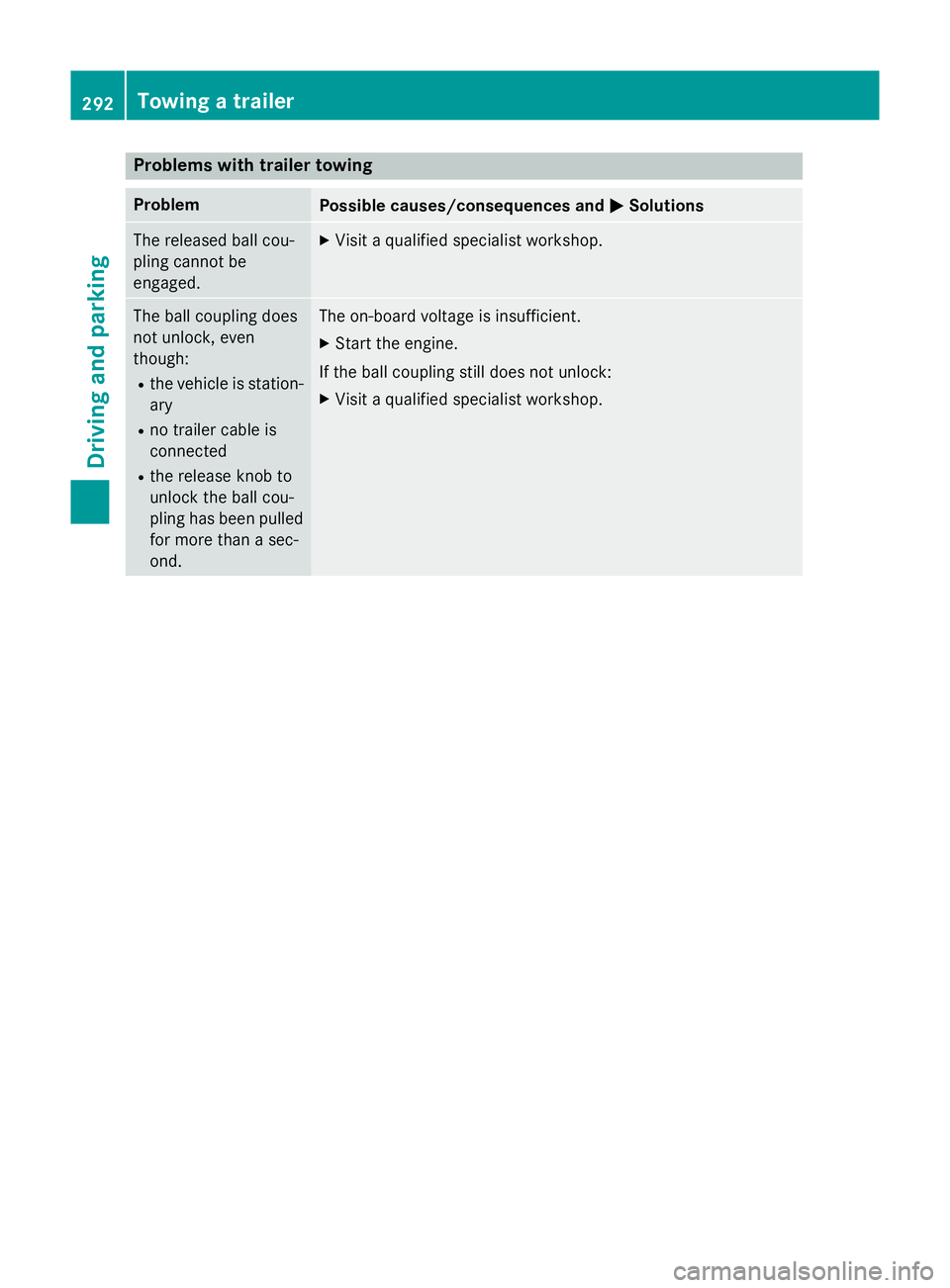
Problems with trailer towing
Problem
Possible causes/consequences and
M
MSolutions The released ball cou-
pling cannot be
engaged. X
Visit a qualified specialist workshop. The ball coupling does
not unlock, even
though:
R the vehicle is station-
ary
R no trailer cable is
connected
R the release knob to
unlock the ball cou-
pling has been pulled
for more than a sec-
ond. The on-board voltage is insufficient.
X Start the engine.
If the ball coupling still does not unlock: X Visit a qualified specialist workshop. 292
Towing a trailerDriving and parking
Page 296 of 489
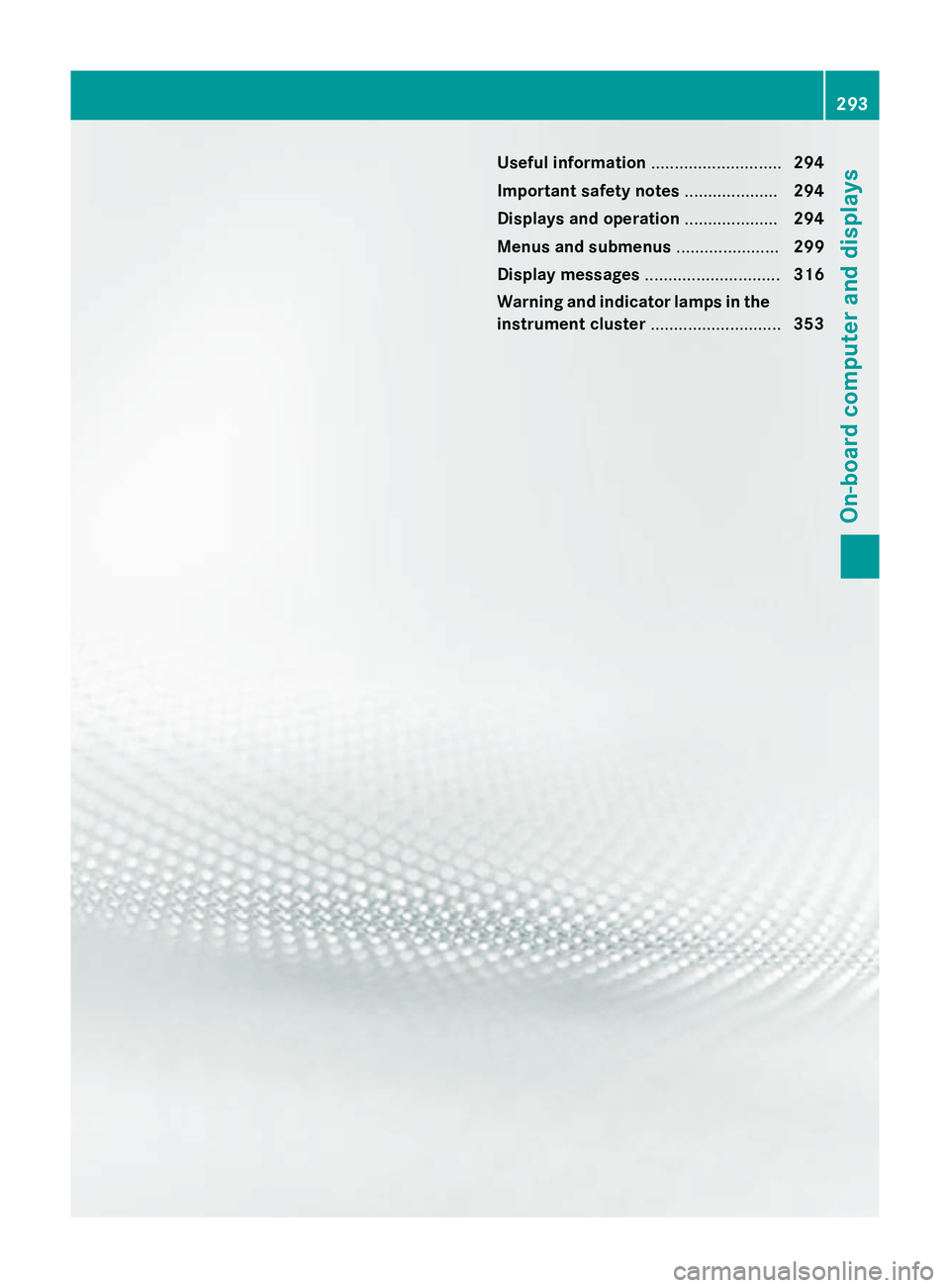
Useful information
............................294
Important safety notes ....................294
Displays and operation ....................294
Menus and submenus ......................299
Display messages ............................. 316
Warning and indicator lamps in the instrument cluster ............................353 293On-board computer and displays
Page 297 of 489
Useful information
i This Owner's Manual describes all mod-
els, series and optional equipment for your
vehicle that were available at the time of
going to press. National variations are pos- sible. Note that your vehicle may not be
equipped with all of the functions descri-
bed. This is also the case for systems and
functions relevant to safety.
i Read the information on qualified special-
ist workshops: (Y page 27). Important safety notes
G
WARNING
Operating the integrated information systems and communications equipment in the vehicle
while driving will distract you from traffic con-
ditions. You could then lose control of the
vehicle. There is a risk of an accident.
Only operate these devices if road traffic con-
ditions permit. If you are unsure about the
surrounding conditions, pull over to a safe
location and make entries only while the vehi-
cle is stationary.
You must observe the legal requirements for
the country in which you are currently driving when operating the on-board computer. G
WARNING
If the instrument cluster has failed or mal-
functioned, you may not recognise function
restrictions relevant to safety. The operating
safety of your vehicle may be impaired. There is a risk of an accident.
Drive on carefully. Have the vehicle checked
at a qualified specialist workshop immedi-
ately.
The on-board computer only shows messages
or warnings from certain systems in the mul- tifunction display. You should therefore make
sure your vehicle is operating safely at all
times. If the operating safety of your vehicle is
impaired, park the vehicle safely as soon as
possible. Contact a qualified specialist work-
shop.
For an overview, see the instrument cluster
illustration (Y
page 34). Displays and operation
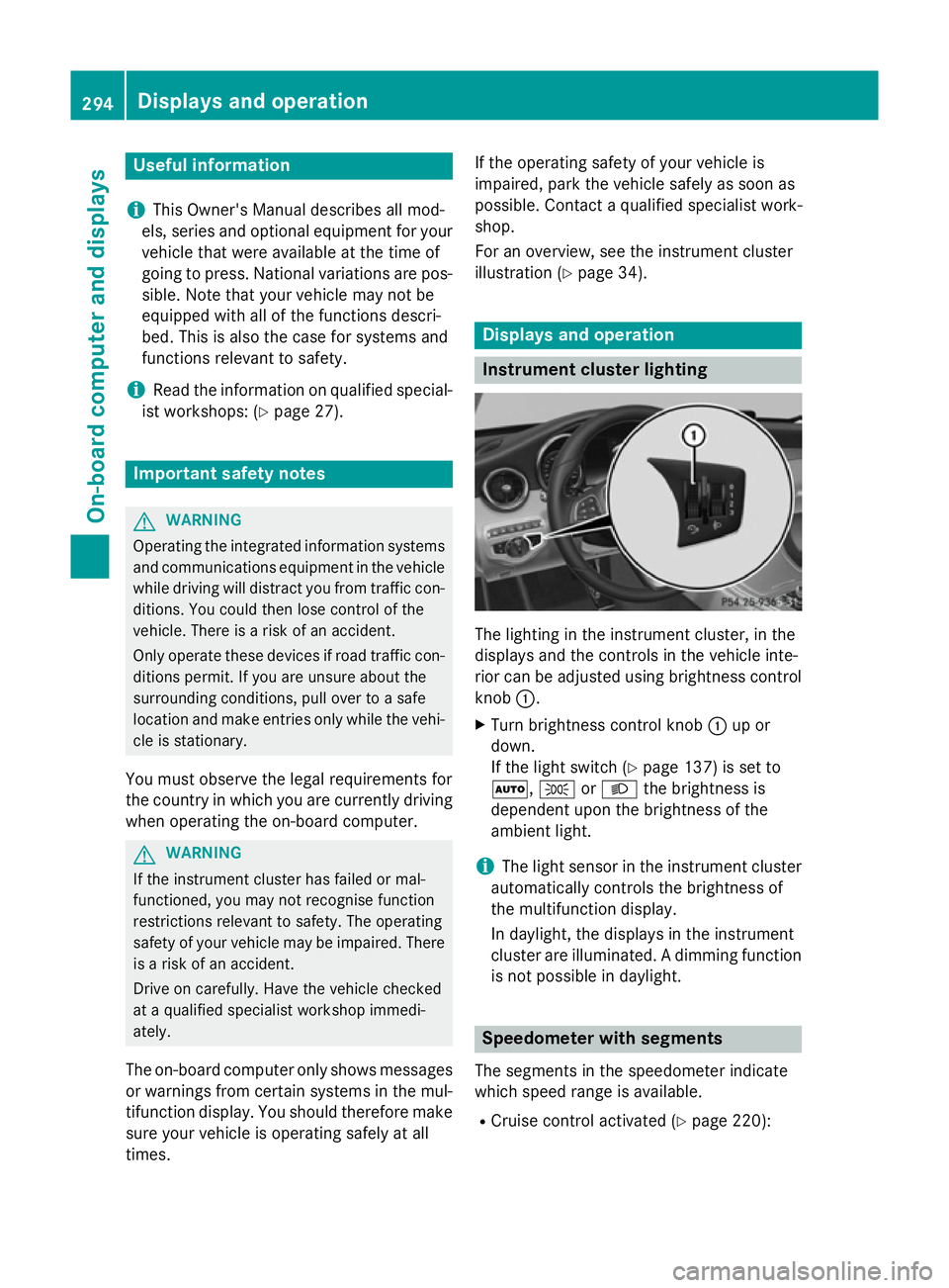
Instrument cluster lighting
The lighting in the instrument cluster, in the
displays and the controls in the vehicle inte-
rior can be adjusted using brightness control
knob :.
X Turn brightness control knob :up or
down.
If the light switch (Y page 137) is set to
Ã, TorL the brightness is
dependent upon the brightness of the
ambient light.
i The light sensor in the instrument cluster
automatically controls the brightness of
the multifunction display.
In daylight, the displays in the instrument
cluster are illuminated. A dimming function
is not possible in daylight. Speedometer with segments
The segments in the speedometer indicate
which speed range is available. R Cruise control activated (Y page 220):294
Displays and operationOn-board computer and displays
Page 298 of 489
The segments light up from the stored
speed to the maximum speed.
R Variable SPEEDTRONIC activated
(Y page 223):
The segments light up from the start of the
scale to the selected limit speed.
R DISTRONIC PLUS activated (Y page 226):
One or two segments in the set speed
range light up.
R DISTRONIC PLUS detects a vehicle in front
that is driving at a slower speed than the
stored speed:
The segments between the speed of the
vehicle in front and the stored speed light
up. Rev counter
! Do not drive in the overrevving range.
Doing so will damage the engine.
The red band in the rev counter indicates the engine's overrevving range.
The fuel supply is interrupted to protect the
engine when the red band is reached. Outside temperature display
You should pay special attention to road con- ditions when temperatures are around the
freezing point.
Bear in mind that the outside temperature
display indicates the temperature measured
and does not record the road temperature.
The outside temperature display is in the mul-
tifunction display (Y page 297).
Changes in the outside temperature are dis-
played after a short delay. Coolant temperature gauge
G
WARNING
If you open the bonnet while the engine is
overheating or while there is a fire in the
engine compartment, you could come into contact with hot gases or other leaking ser-
vice products. There is a danger of injury.
Allow an overheating engine to cool down
before opening the bonnet. If there is a fire in
the engine compartment, leave the bonnet
closed and notify the fire brigade.
The analogue coolant temperature gauge is in
the instrument cluster on the right-hand side (Y page 34).
In the on-board computer in the Service Service
menu there is a digital coolant temperature
gauge (Y page 309).
Under normal operating conditions and with
the specified coolant level, the coolant tem-
perature may rise to 120 †.
At high outside temperatures and when driv-
ing uphill, the coolant temperature may rise
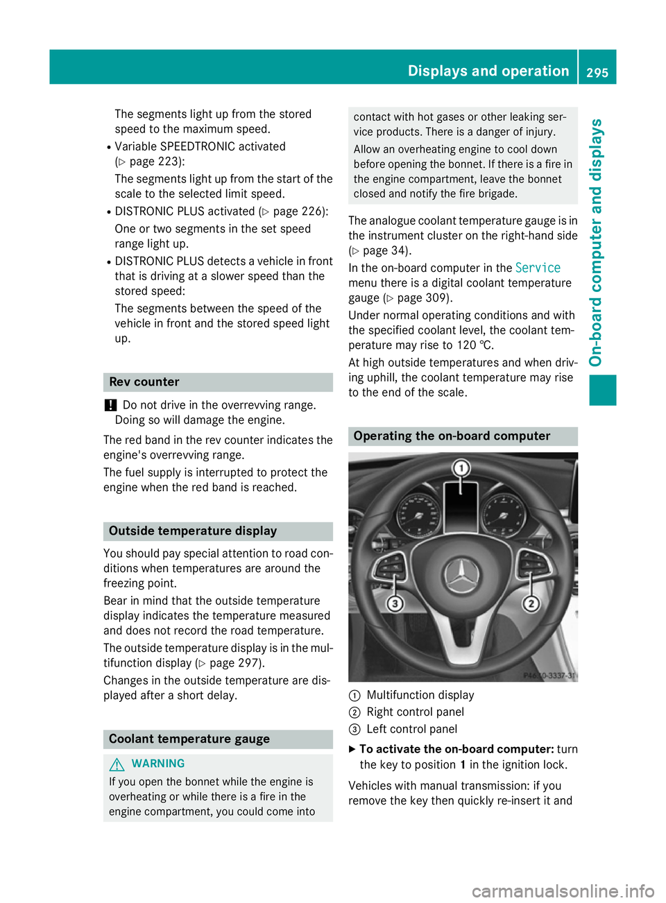
to the end of the scale. Operating the on-board computer
:
Multifunction display
; Right control panel
= Left control panel
X To activate the on-board computer: turn
the key to position 1in the ignition lock.
Vehicles with manual transmission: if you
remove the key then quickly re-insert it and Displays and operation
295On-board computer and displays Z
Page 299 of 489
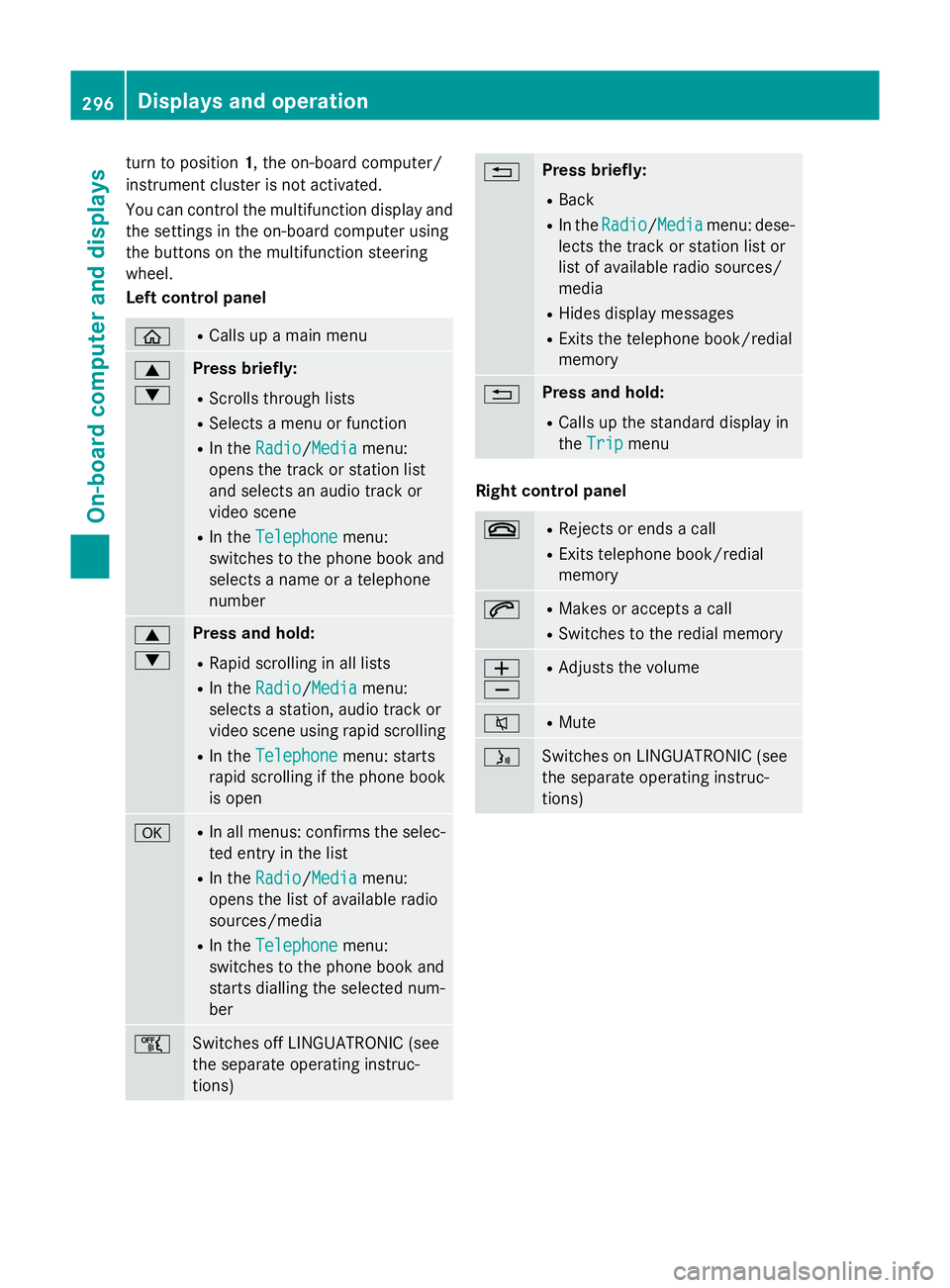
turn to position
1, the on-board computer/
instrument cluster is not activated.
You can control the multifunction display and
the settings in the on-board computer using
the buttons on the multifunction steering
wheel.
Left control panel ò R
Calls up a main menu 9
: Press briefly:
R Scrolls through lists
R Selects a menu or function
R In the Radio Radio/ Media
Mediamenu:
opens the track or station list
and selects an audio track or
video scene
R In the Telephone Telephone menu:
switches to the phone book and
selects a name or a telephone
number 9
: Press and hold:
R Rapid scrolling in all lists
R In the Radio Radio/ Media
Mediamenu:
selects a station, audio track or
video scene using rapid scrolling
R In the Telephone
Telephone menu: starts
rapid scrolling if the phone book is open a R
In all menus: confirms the selec-
ted entry in the list
R In the Radio
Radio/ Media
Media menu:
opens the list of available radio
sources/media
R In the Telephone
Telephone menu:
switches to the phone book and
starts dialling the selected num-
ber ñ
Switches off LINGUATRONIC (see
the separate operating instruc-
tions) % Press briefly:
R Back
R In the Radio Radio/ Media
Mediamenu: dese-
lects the track or station list or
list of available radio sources/
media
R Hides display messages
R Exits the telephone book/redial
memory % Press and hold:
R Calls up the standard display in
the Trip Trip menu Right control panel
~ R
Rejects or ends a call
R Exits telephone book/redial
memory 6 R
Makes or accepts a call
R Switches to the redial memory W
X R
Adjusts the volume 8 R
Mute ó
Switches on LINGUATRONIC (see
the separate operating instruc-
tions)296
Displays and operationOn-boa
rdcompu ter and displays
Page 300 of 489
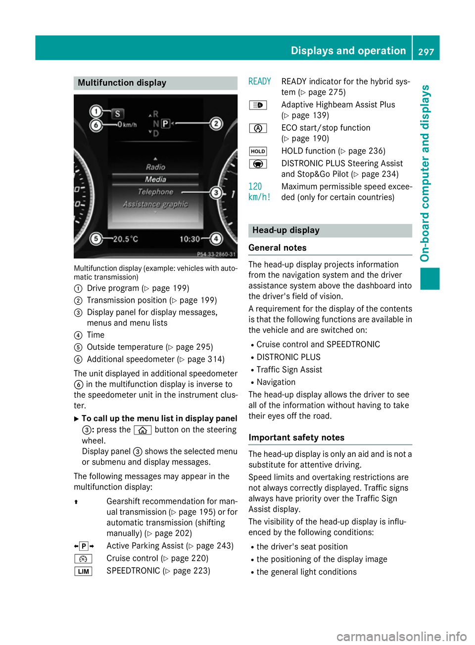
Multifunction display
Multifunction display (example: vehicles with auto-
matic transmission)
: Drive program (Y page 199)
; Transmission position (Y page 199)
= Display panel for display messages,
menus and menu lists
? Time
A Outside temperature (Y page 295)
B Additional speedometer (Y page 314)
The unit displayed in additional speedometer
B in the multifunction display is inverse to
the speedometer unit in the instrument clus-
ter.
X To call up the menu list in display panel
=: press the òbutton on the steering
wheel.
Display panel =shows the selected menu
or submenu and display messages.
The following messages may appear in the
multifunction display:
Z Gearshift recommendation for man-
ual transmission (Y page 195) or for
automatic transmission (shifting
manually) (Y page 202)
XjY Active Parking Assist (Y page 243)
¯ Cruise control (Y page 220)
È SPEEDTRONIC (Y page 223) READY
READY READY indicator for the hybrid sys-
tem (Y
page 275)
_ Adaptive Highbeam Assist Plus
(Ypage 139)
è ECO start/stop function
(Ypage 190)
ë HOLD function (Y page 236)
a DISTRONIC PLUS Steering Assist
and Stop&Go Pilot (Y page 234)
120
120
km/h! km/h! Maximum permissible speed excee-
ded (only for certain countries) Head-up display
General notes The head-up display projects information
from the navigation system and the driver
assistance system above the dashboard into
the driver's field of vision.
A requirement for the display of the contents
is that the following functions are available in the vehicle and are switched on:
R Cruise control and SPEEDTRONIC
R DISTRONIC PLUS
R Traffic Sign Assist
R Navigation
The head-up display allows the driver to see
all of the information without having to take
their eyes off the road.
Important safety notes The head-up display is only an aid and is not a
substitute for attentive driving.
Speed limits and overtaking restrictions are
not always correctly displayed. Traffic signs
always have priority over the Traffic Sign
Assist display.
The visibility of the head-up display is influ-
enced by the following conditions:
R the driver's seat position
R the positioning of the display image
R the general light conditions Displays and operation
297On-board computer and displays Z