ECU MERCEDES-BENZ C-CLASS ESTATE 2020 Repair Manual
[x] Cancel search | Manufacturer: MERCEDES-BENZ, Model Year: 2020, Model line: C-CLASS ESTATE, Model: MERCEDES-BENZ C-CLASS ESTATE 2020Pages: 565, PDF Size: 10.27 MB
Page 325 of 565
Blue
tooth ®
profile overview Blue
tooth ®
profile
of the mobile phone Fu
nction
PBAP (Phone Book
Access Profile) Contacts are auto‐
matically displa
yed in
th e multimedia sys‐
tem
MAP (Message
Access Profile) Message functions
can be used Te
lephony operating modes overview
Depending on your equipment, thefo llowing tel‐
ephony operating modes are available:
R A mobile phone is connec tedto the multime‐
dia sy stem via Blue tooth®
(/ page 322).
R Two mobile phones are connected with the
multimedia sy stem via Blue tooth®
(two
phone mode) (/ page 323). Information on
telephony
The following situations can lead tothe call
being disconnected while theve hicle is in
motion:
R there is insuf ficient network co verage inthe
area
R you mo vefrom one GSM or UMTS transmit‐
te r/receiver area (cell) into ano ther and no
communication channels are free
R the SIM card used is not compatible with the
network available
R a mobile phone with "Twincard" is logged into
the network with the second SIM card at the
same time
The multimedia sy stem supports calls in HD
Vo ice ®
for impr oved speech qualit y.Arequ ire‐
ment forth is is that the mobile phone and the
mobile phone network pr ovider of the person
yo u are calling suppo rtHD Voice ®
.
Depending on thequ ality of the connection, the
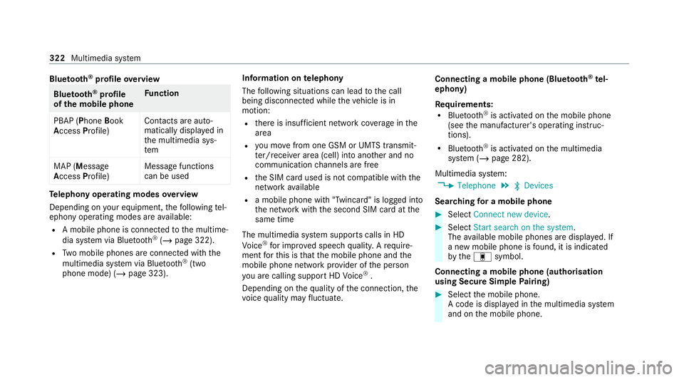
vo ice quality may fluctuate. Connecting a mobile phone (Blue
tooth ®
te l‐
ephony)
Re quirements:
R Blue tooth ®
is activated on the mobile phone
(see the manufacturer's operating instruc‐
tions).
R Blue tooth ®
is activated on the multimedia
sy stem (/ page 282).
Multimedia sy stem:
4 Telephone 5
ª Devices
Sear ching for a mobile phone #
Select Connect new device . #
Select Start search on the system .
The available mobile phones are displa yed. If
a new mobile phone is found, it is indicated
by the# symbol.
Connecting a mobile phone (authorisation
using Secure Simple Pairing) #
Select the mobile phone.
A code is displa yed in the multimedia sy stem
and on the mobile phone. 322
Multimedia sy stem
Page 345 of 565
in
the second stage toenable an optimal
service.
An ove rview of the data transmit ted can be
fo und in there spective term s of use for
Mercedes me connect services. These can be
obtained in the Mercedes me Portal: https://
me.secure.mercedes-benz.com
Data processing
The data transmitted within the scope of the call
is dele ted from the processing sy stem af terthe
call is finished, in so far as this data is not being
used forot her activated Mercedes me connect
services.
The incident-specific data is processed and
st ored in the Mercedes-Benz Cus tomer Centre
and, if requ ired toprocess the incident, forw ar‐
ded tothe service partner authorised bythe
Mercedes-Benz Cus tomer Centre. Please take
no te ofthe data pr otection information on the
Mercedes me Internet page https://
www.mercedes.me or in there corded message
immediately af ter calling the Mercedes-Benz
Cus tomer Centre. %
The recorded message is not available in
eve rycountr y. Mercedes me connect
Information on Mercedes me connect
Mercedes me connect pr
ovides thefo llowing
services:
R Accident and breakdown manage ment (me
button)
R Mercedes-Benz emergency call sy stem (auto‐
matic emer gency call and SOS button)
The Mercedes-Benz Cu stomer Centre and the
Mercedes-Benz emer gency call centre are availa‐
ble foryo u around the cloc k.
The me button and the SOS button can be found
on theve hicle's overhead control panel
(/ page 337).
Yo u can also call the Mercedes-Benz Cus tomer
Centre using the multimedia sy stem
(/ page 339).
Please no tethat Mercedes me connect is a
Mercedes-Benz service. In emer gencies, firs t call th
e national emer gency services using the
st andard national emer gency service telephone
numbers. In emer gencies, you can also use the
Mercedes-Benz emer gency call sy stem
(/ page 343).
Obser vethe conditions of use for Mercedes me
connect and other services. These can be
obtained in the Mercedes me Portal: https://
me.secure.mercedes-benz.com
Fu rther information about Mercedes me con‐
nect, the pr ovided service scope and operation:
https://moba.i.daimler.com/mar kets/ece-r ow/
baix/cars/connectme/en_GB/#emotions/
St artseite.html
Information on Mercedes me connect Acci‐
dent and Breakdown Management
The Accident and Breakdown Management can
include thefo llowing functions:
R Supplement tothe Mercedes-Benz emer‐
ge ncy call sy stem (/ page 343)
If necessar y,the conta ct person at the
Mercedes-Benz emer gency call centre for‐
wa rdsth e call toMercedes me connect Acci‐
dent and Breakdown Management. Forw ard‐ 342
Multimedia sy stem
Page 346 of 565
ing
the call is ho wever not possible in all
countries.
R Breakdown assi stance byate ch nician on
location and/or theto wing away oftheve hi‐
cle tothe nearest Mercedes-Benz service
cent re
Yo u may be charge dfo rth ese services.
More information about Mercedes me connect
services can be obtained in the Mercedes me
Po rtal: https://me.secure.mercedes-benz.com
Data trans ferred duri ng Mercedes me con‐
nect call services
The data transfer red during a Mercedes me con‐
nect call depends on:
R The reason for initiation of the call
R The service that is selec ted in thevo ice con‐
trol sy stem
R The activated Mercedes me connect services
Which data is transfer redfo rth e services can be
ta ke n from the cur rently valid term s of use.
These can be obtained in the Mercedes me por‐
ta l: https://me.secure.mercedes-benz.com Mercedes-Benz emer
gency call sy stem Information on
the Mercedes-Benz emer‐
ge ncy call sy stem
The Mercedes-Benz emer gency call sy stem only
functions in areas where mobile phone co verage
is available from the mobile phone network pro‐
viders. Insuf ficient network co verage from the
mobile phone network pr oviders may result in an
emergency call not being transmitted.
The Mercedes-Benz emer gency call sy stem is
av ailable for at least tenye ars starting from the
manufacturing date.
The ignition must be switched on before an auto‐
matic emergency call can be made.
% The Mercedes-Benz emerge ncy call system
is activated at thefa ctor y.
Overview of the Mercedes-Benz emer gency
call sy stem
The Mercedes-Benz emer gency call sy stem can
help todecisively reduce the time between an
accident and the ar riva l of emer gency services
at the site of the accident. It helps locate an
accident site in places that are dif ficult to
access. The emer
gency call can be made au tomatical ly
( / page 343) or manually (/ page 344). Only
make emer gency calls if you or others are in
need of rescue. Do not make an emergency call
in theeve nt of a breakdown or a similar situa‐
tion.
Displ ays in the media display
SOS READY : eCallavailable
SOS NOT READY: the ignition is not on or eCall
is not available.
During an active emer gency call, Gappears
in the displa y.
Yo u can find more information on there gional
av ailability of eCall at: https://www.mercedes-
benz-mobile.com/ext ra/ecall/
% Ifth ere is a malfunction in the emer gency
call sy stem (e.g. a fault with the speaker,
microphone, airbag, SOS button), a cor re‐
sponding message appears inthe multifunc‐
tion display of the instrument clus ter.
Tr iggering an automatic emer gency call
Re quirements:
R The ignition is switched on. Multimedia sy
stem 343
Page 398 of 565

Setting up
thewa rning triangle #
Fold side reflectors 1upwards toform a tri‐
angle and attach at theto p using upper
press-stud 2. #
Fold legs 3down and out tothe side. Fi
rs t-aid kit (soft-sided) overview Fir
st-aid kit (so ftsided) 1is in the load com‐
partment in the left-hand stowage net. Re
moving the fire extinguisher &
WARNING Risk of accident due toan
incor rectly secu redfire extinguisher in
th e driver's foot we ll
A fire extinguisher may impede pedal tr avel
or block a depressed pedal.
This jeopardises the operating and road
saf ety of theve hicle.
The fire extinguisher can be flung around and
injure the driver or other vehicle occupants. #
Alw aysst ore and secure thefire extin‐
guisher in the brac ket. #
Do not remo vethefire extinguisher
while driving. Breakdown assi
stance 395
Page 409 of 565
Obser
vethefo llowing points during starting
assis tance and when charging the battery:
R Only use undamaged jump lead/charging
cables with a suf ficient cross-section and
insula tedte rm inal clamps.
R Non- insulated parts of thete rm inal clamps
must not come into con tact wi thother me tal
parts while the jump lead/charging cable is
connected tothe battery/jump-s tart connec‐
tion point.
R The jump lead/charging cable must not
come into contact wi thany parts which may
mo vewhen the engine is running.
R Alw ays make sure that nei ther you nor the
battery is elect rostatically charge d.
R Keep away from fire and naked flames.
R Do not lean overth e batter y.
Obser vethe additional following points when
ch arging the battery:
R Only use battery charge rs tested and
appr oved for Mercedes-Benz.
R Read the battery charge r's operating instruc‐
tions before charging the batter y. Obser
vethe additional following points during
st arting assis tance:
R Starting assis tance may only be pr ovided
using vehicles, batteries or other jump start
devices with a nominal voltage of 12V.
R The vehicles must not touch.
R Vehicles with a petrol engine: jump-start
th eve hicle only when the engine and exhaust
sy stem are cold. St
arting assi stance and charging the12 V
battery Preparing
starting assi stance/charging #
Secure theve hicle byapplying the electric
parking brake. #
Automatic transmission: shiftthe trans‐
mission toposition j. #
Manual transmission: shiftthe transmis‐
sion toneutral. #
Switch off the ignition and all electrical con‐
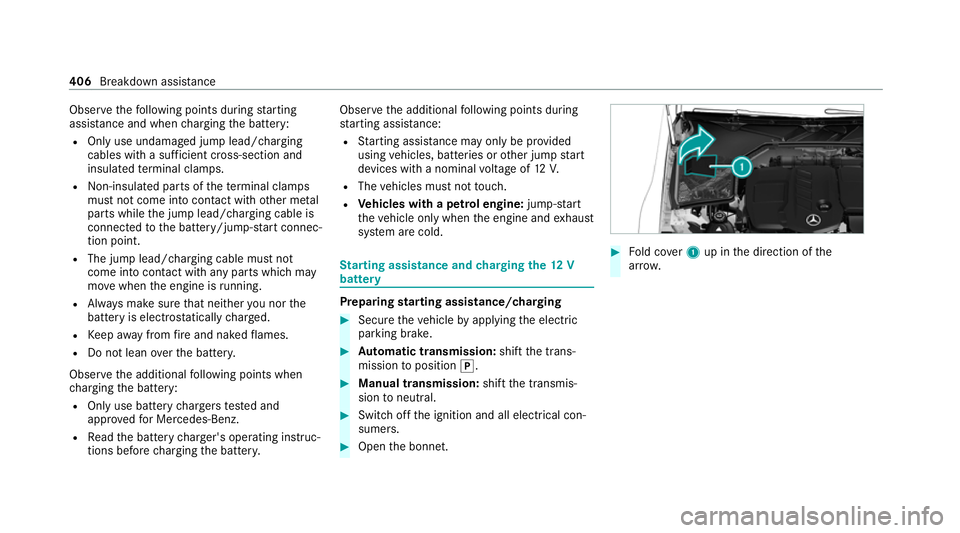
sumers. #
Open the bonn et. #
Fold co ver1 up in the direction of the
ar row. 406
Breakdown assis tance
Page 414 of 565

*
NO
TEDama gedue toexcessive tracti ve
po wer If
yo u pull away sharpl y,the tractive po wer
may be too high and theve hicles could be
damaged. #
Pull away slowly and smoo thly. Loading the
vehicle for transport #
Obser vethe no tes on towing away
( / page 409). #
Connect theto w bar totheto wing eye in
order toload theve hicle.
% You can also attach theto w bar tothe trailer
hitch. #
Vehicles with automatic transmission:
shift the automatic transmission toposition
i.
% Ve
hicles with automatic transmission:
th e automatic transmission may be loc ked in
position jintheeve nt of damage tothe
electrical sy stem. Toshift toi , pr ovide the on-board electrical sy
stem with po wer
( / page 406). #
Load theve hicle onto the transpor ter. #
Vehicles with automatic transmission:
shift the automatic transmission toposition
j. #
Use the electric parking brake tosecure the
ve hicle against rolling away. #
Only secure theve hicle bythe wheels.
Ve hicles with ADS PLUS (Adaptive Damping
Sy stem PLUS) &
WARNING Risk of an accident when
transporting vehicles with Adaptive
Damping Sy stem PLUS
When transporting vehicles with Adaptive
Damping Sy stem PLUS, theve hicle/trailer
combination may begin torock andstart to
skid. #
When transporting, ensure that:
R theve hicle has been loaded onto
th e transpor ter cor rectly R
theve hicle is secured at all four
wheels with suitable tensioning
st ra ps
R the maximum permissible speed of
60 km/h is not exceeded when
transporting *
NO
TEDama getotheve hicle from secur‐
ing it incor rectly #
After loading, theve hicle must be
secured on all four wheels. Otherwise,
th eve hicle could be damaged. #
A minimum dis tance of 20 cm up wards
and 10cm down wards must be kept to
th e transport platform. #
Secure theve hicle on all four wheels af ter
loading. Breakdown assis
tance 411
Page 417 of 565
#
When the fuse box is open, make sure
th at no moisture can enter the fuse
box. #
When closing the fuse box, make sure
th at the seal of the lid is positioned cor‐
re ctly on the fuse box. If
th e newly inser ted fuse also blo ws, ha vethe
cause traced and rectified at a qualified special‐
ist workshop.
Ensure thefo llowing before replacing a fuse:
R The vehicle is secured against rolling away.
R All electrical consumers are switched off.
R The ignition is switched off.
The electrical fuses are located in various fuse
bo xes:
R Fuse box in the engine compartment on the
driver's side (/ page414)
R Fuse box on the driver's side of the cockpit
(/ page 415)
R Fuse box in the front passenger foot we ll
(/ page 415) R
Fuse box in the load compartment on the
ri ght-hand side of theve hicle, when vie wed
in the direction of tra vel (/ page 416) Opening and closing
the fuse box in the
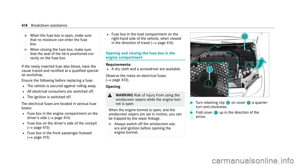
engine compa rtment Re
quirements:
R A dry clo thand a sc rewdriver are available.
Obse rveth e no tes on electrical fuses
(/ page 413).
Opening &
WARNING Risk of injury from usingthe
windscreen wipers while the engine bon‐
net is open
When the engine bonn etis open, and the
windscreen wipers are set in motion, you can
be trapped bythe wiper linkage. #
Alw ays switch off the windscreen wip‐
ers and ignition before opening the
engine bonn et. #
Turn retai ning clip 2on co ver1 aqu arter-
turn anti-clo ckwise. #
Fold co ver1 up in the direction of the
ar row. 414
Breakdown assis tance
Page 434 of 565

#
Ensu rethat the wheel bolts or wheel
nuts are tightened tothe prescribed
tightening torque. #
Ifyo u are not sure, do not mo vethe
ve hicle. Contact a qualified specialist
wo rkshop and ha vethe tightening tor‐
qu ech ecked immediately. #
Check the tyre pressure of the newly fitted
wheel and adjust it if necessa ry.#
Vehicles with a tyre pressure monitoring
sy stem: restart the tyre pressure monitoring
sy stem (/ page 420).
Exception: the new wheel is an emer gency
spa rewheel. Emer
gency spare wheel Note
s onthe emer gency spare wheel &
WARNING Risk of accident caused by
incor rect wheel and tyre dimensions
The wheel or tyre size and the tyre type of
th e emer gency spa rewheel or spare wheel
and the wheel tobe replaced may dif fer. The
emer gency spa rewheel or spare wheel can
significantly impair driving characteristics of
th eve hicle.
To preve nt hazardous situations: #
Drive carefully. #
Neverfit more than one emer gency
spa rewheel or spare wheel that dif fers
in size. #
Only use an emer gency spa rewheel or
spare wheel brief ly. #
Do not deacti vate ESP ®
. #
Have the emer gency spa rewheel or
spare wheel of a dif fere nt size replaced
at the nearest qualified specialist work‐ shop. The new wheel must ha
vethe
cor rect dimensions. %
The emergency spa rewheel is secured in the
emer gency spa rewheel bag in the load com‐
partment.
Obser vethefo llowing no tes on fitting an emer‐
ge ncy spa rewheel:
R Check the tyre pressure of the emer gency
spa rewheel fitted. Co rrect the pressure as
necessar y.
R The maximum permissible speed with an
emer gency spa rewheel fitted is 80 km/h.
R Do not fit th e emer gency spa rewheel with
sn ow ch ains.
R Replace the emer gency spa rewheel af ter six
ye ars at the latest, rega rdless of wear. Wheels and tyres
431
Page 457 of 565

Display messages
Possible causes/consequences and M MSolutions &
WARNING Risk of injury or death when using a child restra int sy stem while the front passenger airbag is
enabled
If yo u secure a child in a child restra int sy stem on the front passenger seat and the front passenger airbag is
enabled, the front passenger airbag can deploy in theeve nt of an accident.
The child could be stru ck bythe airbag. #
Ensure, bo thbefore and during the journe y,that thest atus of the front passenger airbag is cor rect.
NEVER use a rear wa rdfacing child restra int on a seat pr otected byan ACTIVE AIRB AGin front of it, DE ATH or
SERIOUS INJU RYtotheCH ILD can occur. #
Stop theve hicle immediately in accordance with the traf fic conditions. #
Makesure that no objects are trapped under the front passenger seat. #
Check thest atus of automatic front passenger airbag actuation (/ page 48).#
If necessar y,consult a qualified specialist workshop immediatel y.
PRE-SAFE inoperative See
Owner's Manual *
The PRE‑SAFE ®
functions are malfunctioning. #
Consult a qualified specialist workshop. 454
Display messages and warning/indicator lamps
Page 465 of 565

Ve
hicle Display messages
Possible causes/consequences and M MSolutions
d Vehicle is operational
Switch off ignition before
exiting *Y
ou are leaving theve hicle in a ready-to-drive state. #
When you lea vetheve hicle, switch off the ignition, secure theve hicle against rolling away and take theke y with
yo u. #
Ifyo u do not lea vetheve hicle, switch off the electrical consumers, e.g. the seat heating. Otherwise, the12 V
battery may dischar geand it will then be possible tostart theve hicle only with the aid of a second battery
(s ta rting assis tance).
ï Check trailer hitch lock *T
he trailer hitch is not operational during a journey with a trailer. &
WARNING Risk of an accident if the ball neck is not loc ked
The trailer may become de tach ed. #
Stop theve hicle immediately in accordance with the traf fic conditions. Do not continue driving. #
Uncouple the trailer and secure it against rolling away. #
Initiate a new swivel mo vement and do not re-couple the trailer until thewa rning/indicator lamp goes out. #
Initiate a new swivel mo vement (/ page244). #
When the display message disappears, couple up the trailer and drive on.
If th e display message does not disappear, the trailer hitch is malfunctioning and the ball neck is not loc ked. 462
Display messages and warning/indicator lamps