indicator MERCEDES-BENZ C230 KOMPRESSOR COUPE 2002 CL203 User Guide
[x] Cancel search | Manufacturer: MERCEDES-BENZ, Model Year: 2002, Model line: C230 KOMPRESSOR COUPE, Model: MERCEDES-BENZ C230 KOMPRESSOR COUPE 2002 CL203Pages: 399
Page 76 of 399
73 Restraint systems
Te ch n i c a l
data Instruments
and controlsOperationDrivingInstrument
cluster displayPractical hints Car care Index The operational readiness of the airbag system is
verified by the indicator lamp “SRS” in the instrument
cluster when turning the electronic key in starter switch
to position 1. When turning the electronic key in starter
switch to position 2 the indicator lamp “SRS” in the
instrument cluster comes on. If no fault is detected, the
lamp will go out when the engine is running. After the
lamp goes out, the system continues to monitor the
components and circuitry of the airbag system and will
indicate a malfunction by coming on again. If the lamp
does not come on at all or if it fails to extinguish or if it
comes on thereafter, a malfunction in the system has
been detected.
The following system components are monitored or
undergo a self-check: crash-sensor(s), airbag ignition
circuits, front seat belt buckles, emergency tensioning
retractors, seat sensor.
Have the system checked at your authorized
Mercedes-Benz Center immediately.
In the operational mode, after the indicator lamp has
gone out following the initial check, interruptions or
short circuits in the airbag ignition circuit and in the
driver and front passenger seat belt buckle harnesses,
and low voltage in the entire system are detected and
indicated.Note:
See page 285 for information on the supplemental
restraint system (SRS) indicator lamp.
Wa r n i n g !
In the event a malfunction of the “SRS” is indicated
as outlined above, the “SRS” may not be
operational. For your safety, we strongly
recommend that you visit an authorized
Mercedes-Benz Center immediately to have the
system checked; otherwise the “SRS” may not be
activated when needed in an accident, which could
result in serious or fatal injury, or it might deploy
unexpectedly and unnecessarily which could also
result in injury.
Page 77 of 399
74 Restraint systems
Te ch n i c a l
data Instruments
and controlsOperationDrivingInstrument
cluster displayPractical hints Car care Index
The driver and passenger front airbags are designed to
activate only in certain frontal impacts exceeding a
preset threshold. The front passenger airbag deploys
only if the front passenger seat is occupied and the
ü indicator lamp in the center console is not
illuminated.Note:
Heavy objects on the front passenger seat can appear to
the “SRS” to indicate the presence of an occupant in
that seat which causes the passenger front airbag to
deploy in a crash exceeding the appropriate threshold.
Page 100 of 399
97 Instrument cluster
Te ch n i c a l
data Instruments
and controlsOperationDrivingInstrument
cluster displayPractical hints Car care Index 1Knob for instrument cluster illumination,
seepage99
Reset knob for trip odometer, see page 101 and
individual settings, see page 121
2Tachometer
3Speedometer
4Left turn signal indicator lamp, see combination
switch on page 148
5Electronic stability program (ESP) warning lamp,
see page 288
6Indicator lamp without function. It illuminates with
the electronic key in starter switch position 2. It
should go out when the engine is running.
7Right turn signal indicator lamp, see combination
switch on page 148
8Indicator lamp without function. It illuminates with
the electronic key in starter switch position 2. It
should go out when the engine is running.9Multifunction display, see page 102
Malfunction and warning messages in the
multifunction display, see page 290
10Trip odometer, see page 101 and 106
11Main odometer, see page 106
12Display for program mode and gear range
indicators, page 249
13Malfunction/warning message memory,
seepage119
14Outside temperature indicator, see page 100
15Digital clock
To set the time, see individual settings on page 121
16Fuel gauge with reserve warning lamp, see page 286
Page 101 of 399
98 Instrument cluster
Te ch n i c a l
data Instruments
and controlsOperationDrivingInstrument
cluster displayPractical hints Car care Index
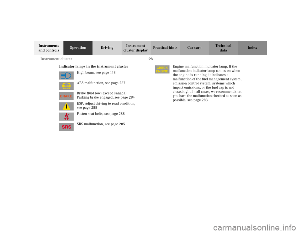
Indicator lamps in the instrument cluster
High beam, see page 148
ABS malfunction, see page 287
Brake fluid low (except Canada).
Parking brake engaged, see page 284
ESP. Adjust driving to road condition,
see page 288
Fasten seat belts, see page 288
SRS malfunction, see page 285Engine malfunction indicator lamp. If the
malfunction indicator lamp comes on when
the engine is running, it indicates a
malfunction of the fuel management system,
emission control system, systems which
impact emissions, or the fuel cap is not
closed tight. In all cases, we recommend that
you have the malfunction checked as soon as
possible, see page 283
ABS
Page 103 of 399
100 Instrument cluster
Te ch n i c a l
data Instruments
and controlsOperationDrivingInstrument
cluster displayPractical hints Car care Index
Outside temperature indicator (14)
The temperature sensor is located in the front bumper
area. Due to its location, the sensor can be affected by
road or engine heat during idling or slow driving. This
means that the accuracy of the displayed temperature
can only be verified by comparison to a thermometer
placed next to the sensor, not by comparison to external
displays (e.g. bank signs etc.).Adaption to ambient temperature takes place in steps
and depends on the prevailing driving conditions (stop-
and-go or moderate, constant driving) and amount of
temperature change.
Note:
The unit for the temperature indicator display can be set
in the individual setting menu “INSTRUMENT
CLUSTER” – “TEMP. INDICATOR” on page 121.
Wa r n i n g !
The outside temperature indicator is not designed
to serve as an Ice-Warning Device and is therefore
unsuitable for that purpose. Indicated
temperatures just above the freezing point do not
guarantee that the road surface is free of ice.
Page 106 of 399
103 Multifunction steering wheel, multifunction display
Te ch n i c a l
data Instruments
and controlsOperationDrivingInstrument
cluster displayPractical hints Car care Index Depending on your vehicle’s equipment, you may use
the buttons on the multifunction steering wheel to call
up, control and set the following systems in the
multifunction display:
1Trip odometer and main odometer, see page 101 and
page 106
Flexible service system (FSS), see page 138
Vehicle speed, see page 106
Coolant temperature gauge, see page 137
Engine oil level indicator, see page 141
2Audio systems, see page 108
Radio, seepage108
CD player, see page 109
Cassette player, see page 1103Navigation system, see page 116
4Malfunction message memory, see page 119
5Individual settings, see page 121
6Trip computer, see page 117
After start
After reset
Fuel tank content
7Telephone, see page 111
Press the è or ÿ button repeatedly until the
required system is displayed.
The display advances by one system each time the
button is pressed.
You may call up additional displays within some of these
categories by pressing the j or k button.
Page 110 of 399
107 Multifunction steering wheel, multifunction display
Te ch n i c a l
data Instruments
and controlsOperationDrivingInstrument
cluster displayPractical hints Car care Index 1Trip odometer and main odometer
See page 101 for instructions on resetting the trip
odometer.
2Coolant temperature gauge, see page 137
3Vehicle speed if “SPEED DISP.” is selected in the
individual setting menu “INSTRUMENT CLUSTER” -
“SELECT DISPLAY”, refer to page 124
Outside temperature if “OUTSIDE TEMPERATURE”
is selected in the individual setting menu
“INSTRUMENT CLUSTER” - “SELECT DISPLAY”, see
page 124
4FSS (Flexible service system), see page 138
5Engine oil level indicator, see page 141Press è or ÿ button repeatedly until the trip
odometer and main odometer display (1) appears.
Press the j or k button repeatedly until the
required display (2, 3, 4, 5, 1) appears.
Pressing the è or ÿ button displays the next or
previous system.
Page 120 of 399
117 Multifunction steering wheel, multifunction display
Te ch n i c a l
data Instruments
and controlsOperationDrivingInstrument
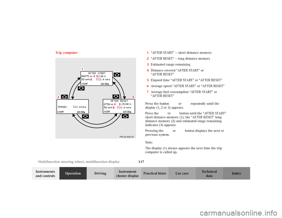
cluster displayPractical hints Car care Index Trip computer 1“AFTER START” — short distance memory
2“AFTER RESET” — long distance memory
3Estimated range remaining
4Distance covered “AFTER START” or
“AFTER RESET”
5Elapsed time “AFTER START” or “AFTER RESET”
6Average speed “AFTER START” or “AFTER RESET”
7Average fuel consumption “AFTER START” or
“AFTER RESET”
Press the button è or ÿ repeatedly until the
display (1, 2 or 3) appears.
Press the j or k button until the “AFTER START”
short distance memory (1), the “AFTER RESET” long
distance memory (2) and estimated range remaining
indicator (3) appears.
Pressing the è or ÿ button displays the next or
previous system.
Note:
The display (1) always appears the next time the trip
computer is called up.
P54.30-4643-27
Page 128 of 399
125 Multifunction steering wheel, multifunction display
Te ch n i c a l
data Instruments
and controlsOperationDrivingInstrument
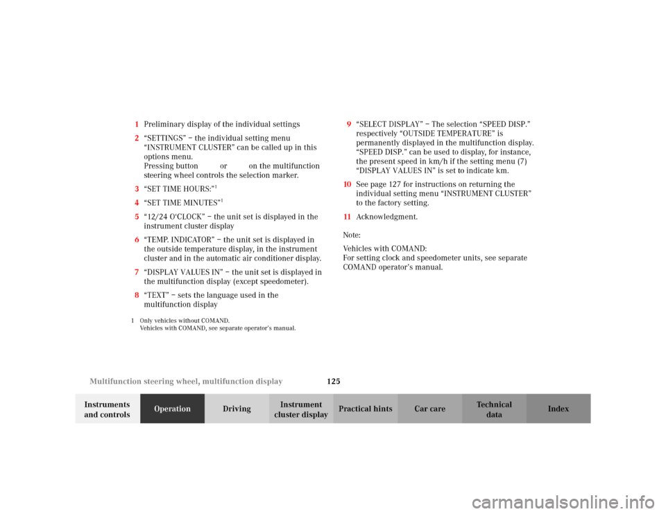
cluster displayPractical hints Car care Index 1Preliminary display of the individual settings
2“SETTINGS” – the individual setting menu
“INSTRUMENT CLUSTER” can be called up in this
options menu.
Pressing buttonæ orç on the multifunction
steering wheel controls the selection marker.
3“SET TIME HOURS:”
1
4“SET TIME MINUTES”
1
5“12/24 O‘CLOCK” – the unit set is displayed in the
instrument cluster display
6“TEMP. INDICATOR” – the unit set is displayed in
the outside temperature display, in the instrument
cluster and in the automatic air conditioner display.
7“DISPLAY VALUES IN” – the unit set is displayed in
the multifunction display (except speedometer).
8“TEXT” – sets the language used in the
multifunction display1 Only vehicles without COMAND.
Vehicles with COMAND, see separate operator’s manual.
9“SELECT DISPLAY” – The selection “SPEED DISP.”
respectively “OUTSIDE TEMPERATURE” is
permanently displayed in the multifunction display.
“SPEED DISP.” can be used to display, for instance,
the present speed in km/h if the setting menu (7)
“DISPLAY VALUES IN” is set to indicate km.
10See page 127 for instructions on returning the
individual setting menu “INSTRUMENT CLUSTER”
to the factory setting.
11Acknowledgment.
Note:
Vehicles with COMAND:
For setting clock and speedometer units, see separate
COMAND operator’s manual.
Page 141 of 399
138 Flexible service system
Te ch n i c a l
data Instruments
and controlsOperationDrivingInstrument
cluster displayPractical hints Car care Index
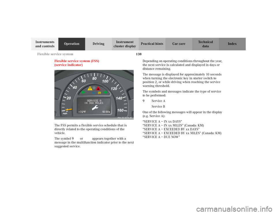
Flexible service system (FSS)
(service indicator)
The FSS permits a flexible service schedule that is
directly related to the operating conditions of the
vehicle.
The symbol 9 or ½ appears together with a
message in the multifunction indicator prior to the next
suggested service.Depending on operating conditions throughout the year,
the next service is calculated and displayed in days or
distance remaining.
The message is displayed for approximately 10 seconds
when turning the electronic key in starter switch to
position 2, or while driving when reaching the service
warning threshold.
The symbols and messages indicate the type of service
to be performed:
9Service A
½Service B
One of the following messages will appear in the display
(e.g. Service A):
“SERVICE A – IN xx DAYS”
“SERVICE A – IN xx MILES” (Canada: KM)
“SERVICE A – EXCEEDED BY xx DAYS”
“SERVICE A – EXCEEDED BY xx MILES” (Canada: KM)
“SERVICE A – DUE NOW”
P54.30-4675-26