MERCEDES-BENZ C320 2002 W203 Owner's Manual
Manufacturer: MERCEDES-BENZ, Model Year: 2002, Model line: C320, Model: MERCEDES-BENZ C320 2002 W203Pages: 406
Page 341 of 406
338 Tires, Wheels
Te ch n i c a l
data Instruments
and controlsOperation DrivingInstrument
cluster displayPractical hintsCar care Index
Sealing tire with TIREFIT
1. Set parking brake and turn on hazard warning
flasher.
2. Move selector lever to position “P” and turn off
engine.
3. Take TIREFIT out of trunk, see page 326.
4. Shake contents of TIREFIT container.
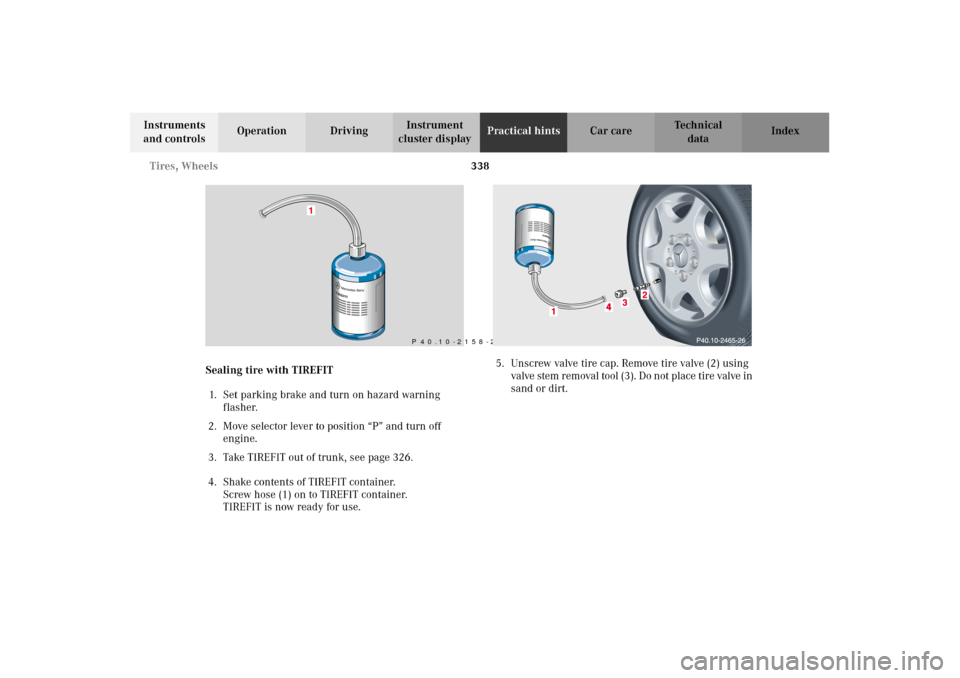
Screw hose (1) on to TIREFIT container.
TIREFIT is now ready for use.5. Unscrew valve tire cap. Remove tire valve (2) using
valve stem r emoval tool (3 ). Do n ot p lace tir e valve in
sand or dirt.
1
P 40.10-2158-26
OM_203.book Seite 338 Donnerstag, 31. Mai 2001 11:57 11
Page 342 of 406
339 Tires, Wheels
Te ch n i c a l
data Instruments
and controlsOperation DrivingInstrument
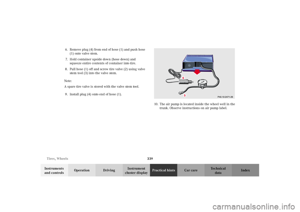
cluster displayPractical hintsCar care Index 6. Remove plug (4) from end of hose (1) and push hose
(1) onto valve stem.
7. Hold container upside down (hose down) and
squeeze entire contents of container into tire.
8. Pull hose (1) off and screw tire valve (2) using valve
stem tool (3) into the valve stem.
Note:
A spare tire valve is stored with the valve stem tool.
9. Install plug (4) onto end of hose (1).
10. The air pump is located inside the wheel well in the
trunk. Observe instructions on air pump label.
OM_203.book Seite 339 Donnerstag, 31. Mai 2001 11:57 11
Page 343 of 406
340 Tires, Wheels
Te ch n i c a l
data Instruments
and controlsOperation DrivingInstrument
cluster displayPractical hintsCar care Index
11. Remove air pump from storage compartment inside
trunk.
12. Pull out air hose with pressure gauge (5) and
electrical plug (6).
13. Screw filler hose (5) onto tire valve.
14. Plug air pump electrical plug (6) into vehicle cigar
lighter.
15. To switch on air pump, turn key in steering lock to
position 1.
Note:
After 5 minutes, pressure gauge must display
26 psi (1.8 bar). Do not exceed the maximum pressure
of 36 psi (2.5 bar)!
If pressure is not attained, drive vehicle
approx. 394 in (10 m), so that the sealing material is
evenly distributed inside the tire. Reconnect air pump
and inflate tire.Note:
Do not operate electric air pump longer that 6 minutes
wit hout interruption. Air pump could overheat! Af ter air
pump has cooled off, operate air pump again.
16. To switch off air pump, turn key in steering lock to
position 0.
17. Reinstall valve tire cap.
18. Drive vehicle to distribute the sealant evenly inside
the tire.
Wa r n i n g !
If a tire pressure of 26 psi (1.8 bar) is not attained,
tire is too severely damaged for TIREFIT to provide
a reliable tire repair.In this case TIREFIT can not properly seal the tire.Do not drive the vehicle.Contact the nearest Mercedes-Benz Center or call
Roadside Assistance.
OM_203.book Seite 340 Donnerstag, 31. Mai 2001 11:57 11
Page 344 of 406
341 Tires, Wheels
Te ch n i c a l
data Instruments
and controlsOperation DrivingInstrument
cluster displayPractical hintsCar care Index Notes:
If TIREFIT is liquid, clean water and a damp cloth will
remove the material from the vehicle or tire and wheel
components. Once TIREFIT sealing material had dried,
it can easily be peeled off and properly discarded.
Replace TIREFIT every 3 years.Tire inflation pressure
A table (see fuel filler flap) lists the tire inflation
pressures specified for Mercedes-Benz recommended
tires as well as for the varying operating conditions.
Important!
Tire pressure changes by approximately 1.5 psi (0.1 bar)
per 18
°F (10
°C) of air temperature change. Keep this in
mind when checking tire pressure inside a garage –
especially in the winter.
Example:
If garage temperature = approximately +68
°F (+20
°C)
and ambient temperature = approximately +32
°F (0
°C)
then the adjusted air pressure = specified air pressure
+3 psi (+0.2 bar).
Tire pressures listed for light loads are minimum values
offering high driving comfort. Increased inflation
pressures for heavy loads produce favorable handling
characteristics with lighter loads and are perfectly
permissible. The ride of the vehicle, however, will
become somewhat harder.
Tire temperature and pressure increase with the vehicle
speed. Tire pressure should therefore only be checked
and corrected on cold tires. Correct tire pressure in
Wa r n i n g !
Do not exceed vehicle speed of 50 mph (80 km / h).
A TIREFIT repair is not designed to operate at
higher speeds.Vehicle handling characteristics may change.After driving vehicle for an initial 10 minutes,
check tire pressure. If tire pressure has fallen
below 20 psi (1.3 bar) do not continue to drive the
vehicle.If tire pressure is at least 20 psi (1.3 bar), inflate
tire to correct pressure (see label on fuel filler
flap), and drive vehicle to nearest tire repair
facility to have tire repaired or replaced.Recommended duration of use: 300 miles (500 km)
at 50 mph (80 km / h) with the recommended tire
pressure.
OM_203.book Seite 341 Donnerstag, 31. Mai 2001 11:57 11
Page 345 of 406
342 Battery
Te ch n i c a l
data Instruments
and controlsOperation DrivingInstrument
cluster displayPractical hintsCar care Index
warm tires only if pressure has dropped below the
pressure listed in the table and the respective operating
conditions are taken into consideration.
An underinflated tire due to a slow leak (e.g. due to a
nail in the tire) may cause damage such as tread
separation, bulging etc. Regular tire pressure checks
(including the spare tire) at intervals of no more than
14 days are therefore essential.
If a tire constantly loses air, it should be inspected for
damage.
The spare tire should be checked periodically for
condition and inflation. Spare tire will age and become
worn over time even if never used, and thus should be
inspected and replaced when necessary.Battery
Important!
Battery replacement information:
The maintenance-free battery is located in the engine
compartment on the right hand side.
The service life of the battery is dependent on its
condition of charge. The battery should always be kept
sufficiently charged, in order to last an optimum length
of time.
Wa r n i n g !
Do not overinflate tires. Overinflating tires can
result in sudden deflation (blowout) because they
are more likely to become punctured or damaged
by road debris, potholes etc. Follow recommended
inflation pressures.Do not overload the tires by exceeding the specified
vehicle capacity weight as indicated by the label on
the driver’s door latch post). Overloading the tires
can overheat them, possibly causing a blowout.
Wa r n i n g !
Failure to follow these instructions can result in
severe injury or death.Never lean over batteries while connecting, you
might get injured.Battery fluid contains sulfuric acid. Do not allow
this fluid to come in contact with eyes, skin or
clot hin g. In cas e i t d oes , i mm ed ia tely f lus h a f fected
area with water and seek medical help if necessary.A battery will also produce hydrogen gas, which is
flammable and explosive. Keep flames or sparks
away from battery, avoid improper connection of
jumper cables, smoking etc.
OM_203.book Seite 342 Donnerstag, 31. Mai 2001 11:57 11
Page 346 of 406
343 Battery
Te ch n i c a l
data Instruments
and controlsOperation DrivingInstrument
cluster displayPractical hintsCar care Index Therefore, we strongly recommend that you have the
battery charge checked frequently, and corrected if
necessary, especially if you use the vehicle less than
approximately 200 miles (300 km) per month,
mostly for short distance trips, or if it is not used for
long periods of time.
Only charge a battery with a battery charger after the
battery has been disconnected from the vehicle’s
electrical circuit.
Always disconnect the battery negative lead first and
connect last.
When removing and connecting the battery, always
make sure that all electrical consumers are off and the
electronic key is in starter switch position 0. The
battery, its filler caps, the vent tube and the opposite
plug must always be securely installed when the vehicle
is in operation.
While the engine is running the battery terminal clamps
must not be loosened or detached, otherwise the
generator and other electronic components would be
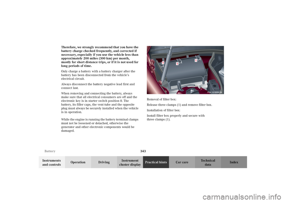
damaged.Removal of filter box:
Release three clamps (1) and remove filter box.
Installation of filter box:
Install filter box properly and secure with
three clamps (1).
OM_203.book Seite 343 Donnerstag, 31. Mai 2001 11:57 11
Page 347 of 406
344 Jump starting
Te ch n i c a l
data Instruments
and controlsOperation DrivingInstrument
cluster displayPractical hintsCar care Index
Note:
The gear selector lever will remain locked in
position “P” and the electronic key can not be turned in
the starter switch, if the vehicle battery is disconnected
or discharged.
After reconnecting the battery also set the clock
(vehicles with COMAND: see COMAND operator’s
manual) resynchronize the front seat head restraints,
the express feature of the power windows, the sliding /
pop-up roof, and the electronic stability program (see
individual settings on page 121, head restraints on
p a ge 5 5 , p owe r w i n d ows o n p a ge 19 7 , s y n ch r o n i zi n g t h e
sliding / pop-up roof on page 202 and electronic stability
program on page 278).
Battery recycling
Batteries contain materials that can harm the
environment with improper disposal.
Large 12 Volt storage batteries contain lead.
Recycling of batteries is the preferred method of
disposal.
Many states require sellers of batteries to accept old
batteries for recycling.Jump starting
Wa r n i n g !
Failure to follow these directions will cause
damage to the electronic components, and can lead
to a battery explosion and severe injury or death.Never lean over batteries while connecting or jump
starting, you might get injured.Battery fluid contains sulfuric acid. Do not allow
this fluid to come in contact with eyes, skin or
clot hin g. In cas e i t d oes , i mm ed ia tely f lus h a f fected
area with water, and seek medical help if
necessary.A battery will also produce hydrogen gas, which is
flammable and very explosive. Keep flames or
sparks away from battery, avoid improper
connection of jumper cables, smoking etc.Read all instructions before proceeding.
OM_203.book Seite 344 Donnerstag, 31. Mai 2001 11:57 11
Page 348 of 406
345 Jump starting
Te ch n i c a l
data Instruments
and controlsOperation DrivingInstrument
cluster displayPractical hintsCar care Index Important!
A discharged battery can freeze at approximately +14
°F
(–10
°C). In that case, it must be thawed out before
jumper cables are used. Attempting to jump start a
frozen battery can result in it exploding, causing
personal injury.
Jumper cable specifications:
•Minimum cable cross-section of 25 mm
2 or
approximately 2 AWG
•Maximum length of 11.5 ft. (3.5 m).
If the battery is discharged, the engine should be started
with jumper cables and the (12 V) battery of another
vehicle.
Only use 12 V battery to jump start your vehicle. Jump
starting with more powerful battery could damage the
vehicle’s electrical systems, which will not be covered
by the Mercedes-Benz Limited Warranty.
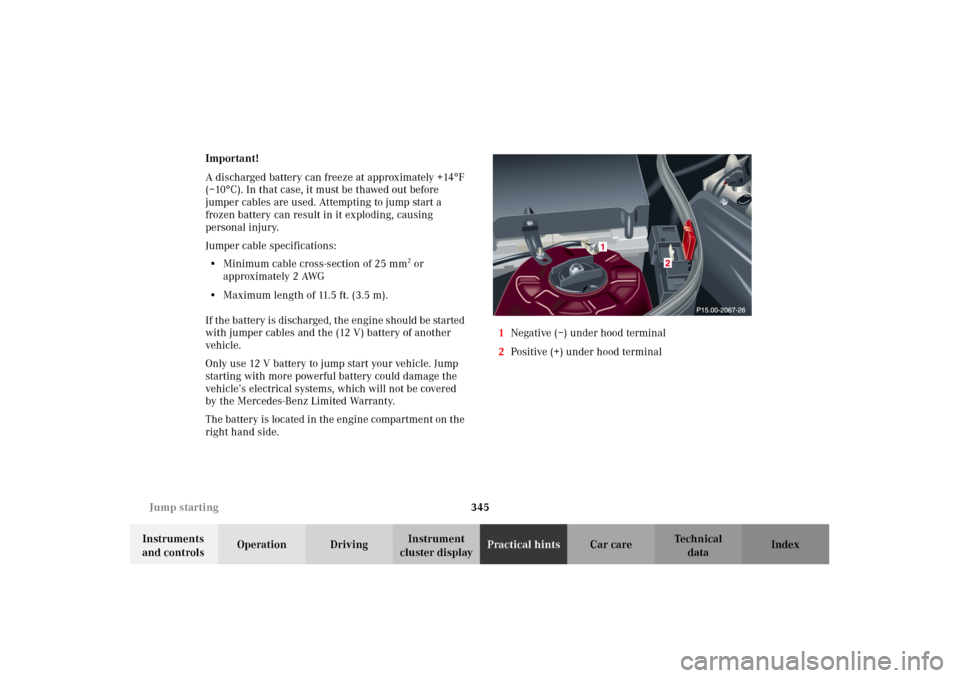
The battery is located in the engine compartment on the
right hand side.1Negative (–) under hood terminal
2Positive (+) under hood terminal
OM_203.book Seite 345 Donnerstag, 31. Mai 2001 11:57 11
Page 349 of 406
346 Jump starting
Te ch n i c a l
data Instruments
and controlsOperation DrivingInstrument
cluster displayPractical hintsCar care Index
Proceed as follows:
1. Position the vehicle with the charged battery so that
the jumper cables will reach, but never let the
vehicles touch. Make sure the jumper cables do not
have loose or missing insulation.
2. On both vehicles:
•Turn off engine and all lights and accessories,
except hazard warning flashers or work lights.
•Apply parking brake and shift selector lever to
position “P” (manual transmission to Neutral).
Important!
3. Clamp one end of the first jumper cable to the
positive (+) under hood terminal of the discharged
battery and the other end to the positive (+) terminal
of the charged battery. Make sure the cable clamps
do not touch any other metal parts.
4. Clamp one end of the second jumper cable to the
grounded negative (–) terminal of the charged
battery and the final connection to the negative (–)
under hood terminal of the disabled vehicle.Important!
5. Start engine of the vehicle with the charged battery
and run at high idle. Make sure the cables are not
on or near pulleys, fans, or other parts that move
when the engine is started. Allow the discharged
battery to charge for a few minutes. Start engine of
the disabled vehicle in the usual manner.
6. After the engine has started, remove jumper cables
by exactly reversing the above installation
sequence, starting with the last connection made
first. When removing each clamp, make sure that it
does not touch any other metal while the other end
is still attached.
Note:
If engine does not run after several unsuccessful
starting attempts, have it checked at the nearest
authorized Mercedes-Benz Center.
Excessive unburned fuel may damage the catalytic
converter.
OM_203.book Seite 346 Donnerstag, 31. Mai 2001 11:57 11
Page 350 of 406
347 Towing the vehicle
Te ch n i c a l
data Instruments
and controlsOperation DrivingInstrument
cluster displayPractical hintsCar care Index Towing the vehicleImportant!
When towing the vehicle, please, note the following:
With the automatic central locking activated and the
electronic key in starter switch position 2, the vehicle
doors lock if the lef t front wheel as well as the right rear
wheel are turning at vehicle speeds of approximately
9 mph (15 km / h) or more.
To prevent the vehicle door locks from locking,
deactivate the automatic central locking. See the
individual setting menu “VEHICLE” – “AUTOMATIC
DOOR LOCK” on page 131.
Towing of the vehicle should only be done using the
properly installed towing eye bolt. Never attach tow
cable, tow rope or tow rod to vehicle chassis, frame
or suspension parts.
Notes:
The selector lever will remain locked in position “P” and
the electronic key cannot be turned in the starter switch
if the battery is disconnected or discharged. See battery
on page 342 or jump starting on page 344.
Transmission selector lever, manually unlocking, see
page 350.
Wa r n i n g !
Prior to towing the vehicle with all wheels on the
ground, make certain that the electronic key is in
starter switch position 2.If the electronic key is left in the starter switch
position 0 for an extended period of time, it can no
longer be turned in the switch. In this case, the
steering is locked. To unlock, remove electronic key
from starter switch and reinsert.When towing another vehicle, observe that the
gross vehicle weight of the vehicle being towed
does not exceed the towing capacity of your vehicle.
OM_203.book Seite 347 Donnerstag, 31. Mai 2001 11:57 11