key MERCEDES-BENZ CL CLASS 2010 Owners Manual
[x] Cancel search | Manufacturer: MERCEDES-BENZ, Model Year: 2010, Model line: CL CLASS, Model: MERCEDES-BENZ CL CLASS 2010Pages: 500, PDF Size: 9.32 MB
Page 302 of 500

otherwise seriously damage the brake
system or the transfer case which is not
covered by the Mercedes-Benz Limited
Warranty.
! Because the ESC operates automatically,
the engine and ignition must be shut off
(SmartKey in starter switch position 0 or
1 or KEYLESS-GO start/stop button in
position 0 or 1) when the electronic parking
brake is being tested on a brake test
dynamometer or when the vehicle is being
towed with one axle raised.
Active braking action through the ESC may
otherwise seriously damage the brake
system which is not covered by the
Mercedes-Benz Limited Warranty. Instrument cluster
Introduction
For a full view illustration of the instrument
cluster, see “Instrument cluster”
(Y page 29). G
Warning!
No messages will be displayed if either the
instrument cluster or the multifunction
display is inoperative.
As a result, you will not be able to see
information about your driving conditions,
such as
R speed
R outside temperature
R warning/indicator lamps
R malfunction/warning messages
R failure of any systems
Driving characteristics may be impaired.
If you must continue to drive, do so with added
caution. Contact an authorized Mercedes-
Benz Center as soon as possible.
The language setting for the multifunction
display can be changed via COMAND
(Y page 81). Activating the instrument cluster
The instrument cluster is activated when you
R open a door
R switch on the ignition
R switch on the exterior lamps Adjusting the instrument cluster
illumination
X
To brighten illumination: Turn knob :
clockwise.
X To dim illumination: Turn knob :
counterclockwise.
i The instrument cluster illumination is
dimmed or brightened automatically to suit
ambient light conditions.
The instrument cluster illumination will also
be adjusted automatically when you switch
on the vehicle’s exterior lamps. Coolant temperature gauge
The coolant temperature gauge is located on
the left side in the instrument cluster
(Y page 29). G
Warning!
Driving when your engine is overheated can
cause some fluids which may have leaked into
the engine compartment to catch fire. You
could be seriously burned. 300
Instrument clusterControls in detail
216_AKB; 3; 90, en-US
d2ureepe,
Version: 2.11.8.1 2009-05-15T11:47:50+02:00 - Seite 300
Page 319 of 500
G
Warning!
The braking effect of the HOLD function is
canceled and the vehicle can start to roll if
R the HOLD function is deactivated by
depressing the accelerator pedal or the
brake pedal
R the HOLD function or the power supply is
malfunctioning, e.g. due to battery failure
R the electrical components in the engine
compartment or the fuses have been
manipulated
R the battery is disconnected G
Warning!
Never get out of the vehicle while the HOLD
function is activated!
The HOLD function must never be operated
or deactivated by passengers or from outside
the vehicle.
The HOLD function does not replace the
electronic parking brake. It must not be used
to secure the vehicle when parking.
Deactivate the HOLD function when leaving
or parking the vehicle. Use the electronic
parking brake to secure the vehicle.
When the HOLD function is activated, the
automatic transmission shifts into park
position P automatically when
R opening the driver’s door and releasing the
seat belt
R turning off the engine
R opening the hood
R a system malfunction occurs
R the on-board voltage is insufficient
The HOLD function is deactivated. AIRMATIC
Introduction The AIRMATIC lets you select the chassis and
suspension setup. The chassis and suspension setup adjusts the damping
behavior and the ride height for your vehicle.
The AIRMATIC consists of two components.
The Adaptive Damping System (ADS)
(Y page 317) and the vehicle level control
(Y page 318).
Adaptive Damping System (ADS)
The Adaptive Damping System (ADS) is
controlled electronically and operates
continuously. It adjusts the damping
characteristics to the current operating and
driving conditions. The damping is adjusted
individually for each wheel. Driving safety and
tire comfort are increased.
The fine tuning of the damping is dependent
on
R your driving style
R road surface conditions
R your personal settings
The selected setting remains stored in
memory even if the SmartKey is removed
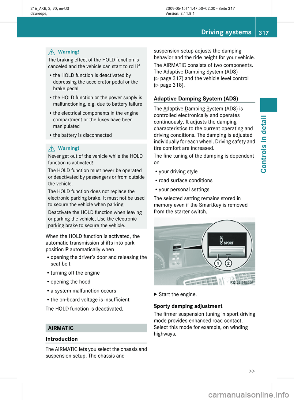
from the starter switch. X
Start the engine.
Sporty damping adjustment
The firmer suspension tuning in sport driving
mode provides enhanced road contact.
Select this mode for example, on winding
highways. Driving systems
317Controls in detail
216_AKB; 3; 90, en-US
d2ureepe, Version: 2.11.8.1 2009-05-15T11:47:50+02:00 - Seite 317 Z
Page 320 of 500
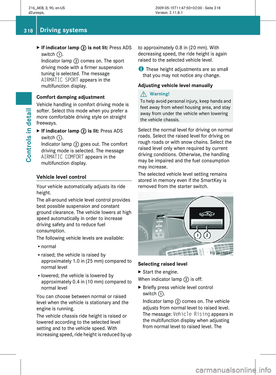
X
If indicator lamp ; is not lit: Press ADS
switch :.
Indicator lamp ; comes on. The sport
driving mode with a firmer suspension
tuning is selected. The message
AIRMATIC SPORT appears in the
multifunction display.
Comfort damping adjustment
Vehicle handling in comfort driving mode is
softer. Select this mode when you prefer a
more comfortable driving style on straight
freeways.
X If indicator lamp ; is lit: Press ADS
switch :.
Indicator lamp ; goes out. The comfort
driving mode is selected. The message
AIRMATIC COMFORT appears in the
multifunction display.
Vehicle level control Your vehicle automatically adjusts its ride
height.
The all-around vehicle level control provides
best possible suspension and constant
ground clearance. The vehicle lowers at high
speed automatically in order to increase
driving safety and to reduce fuel
consumption.
The following vehicle levels are available:
R
normal
R raised; the vehicle is raised by
approximately 1.0 in (25 mm) compared to
normal level
R lowered; the vehicle is lowered by
approximately 0.4 in (10 mm) compared to
normal level
You can choose between normal or raised
level when the vehicle is stationary and the
engine is running.
The vehicle chassis ride height is raised or
lowered according to the selected level
setting and to the vehicle speed. With
increasing speed, ride height is reduced by up to approximately 0.8 in (20 mm). With
decreasing speed, the ride height is again
raised to the selected vehicle level.
i
These height adjustments are so small
that you may not notice any change.
Adjusting vehicle level manually G
Warning!
To help avoid personal injury, keep hands and
feet away from wheel housing area, and stay
away from under the vehicle when lowering
the vehicle chassis.
Select the normal level for driving on normal
roads. Select the raised level for driving on
rough roads or with snow chains. Select the
raised level only when required by current
driving conditions. Otherwise, the handling
may be impaired and the fuel consumption
may increase.
The selected vehicle level setting remains
stored in memory even if the SmartKey is
removed from the starter switch. Selecting raised level
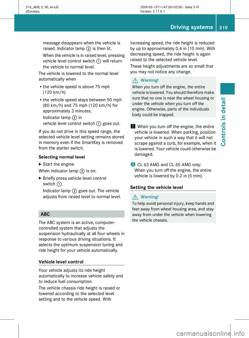
X
Start the engine.
When indicator lamp ; is off:
X Briefly press vehicle level control
switch :.
Indicator lamp ; comes on. The vehicle
adjusts from normal level to raised level.
The message: Vehicle Rising appears in
the multifunction display when adjusting
from normal level to raised level. The 318
Driving systemsControls in detail
216_AKB; 3; 90, en-US
d2ureepe,
Version: 2.11.8.1 2009-05-15T11:47:50+02:00 - Seite 318
Page 321 of 500
message disappears when the vehicle is
raised. Indicator lamp
; is then lit.
When the
vehicle is in raised level, pressing
vehicle level control switch : will return
the vehicle to normal level.
The vehicle is lowered to the normal level
automatically when
R the vehicle speed is above 75 mph
(120 km/h)
R the vehicle speed stays between 50 mph
(80 km/h) and 75 mph (120 km/h) for
approximately 3 minutes.
Indicator lamp
; in
vehicle level control switch : goes out.
If you do not drive in this speed range, the
selected vehicle level setting remains stored
in memory even if the SmartKey is removed
from the starter switch.
Selecting normal level
X Start the engine.
When indicator lamp ; is on:
X Briefly press vehicle level control
switch :.
Indicator lamp ; goes out. The vehicle
adjusts from raised level to normal level. ABC
The ABC system is an active, computer-
controlled system that adjusts the
suspension hydraulically at all four wheels in
response to various driving situations. It
selects the optimum suspension tuning and
ride height for your vehicle automatically.
Vehicle level control Your vehicle adjusts its ride height
automatically to increase vehicle safety and
to reduce fuel consumption.
The vehicle chassis ride height is raised or
lowered according to the selected level
setting and to the vehicle speed. With increasing speed, the ride height is reduced
by up to approximately 0.4 in
(10 mm). With
decreasing speed, the ride height is again
raised to the selected vehicle level.
These height adjustments are so small that
you may not notice any change. G
Warning!
When you turn off the engine, the entire
vehicle is
lowered. You should therefore make
sure that no one is near the wheel housing or
under the vehicle when you turn off the
engine. Otherwise, parts of the individuals
body could be trapped.
! When you turn off the engine, the entire
vehicle is lowered. When parking, position
your vehicle in such a way that it will not
scrape against a curb, for example, when it
is lowered. Your vehicle could otherwise be
damaged.
i CL 63 AMG and CL 65 AMG only:
When you turn off the engine, the entire
vehicle is lowered by 0.2 in (5 mm).
Setting the vehicle level G
Warning!
To help avoid personal injury, keep hands and
feet away from wheel housing area, and stay
away from under the vehicle when lowering
the vehicle chassis. Driving systems
319
Controls in detail
216_AKB; 3; 90, en-US
d2ureepe, Version: 2.11.8.1 2009-05-15T11:47:50+02:00 - Seite 319 Z
Page 336 of 500
look through the windshield. You are always
responsible for safety and must drive in
accordance with traffic conditions.
Otherwise, you could endanger yourself and
others.
The system may be impaired or unavailable
when
R
visibility is poor, e.g. due to snow, rain, fog,
or heavy spray
R the camera area of the windshield is dirty,
fogged up or covered by a sticker for
example
R driving through curves or on inclines or
declines G
Warning!
The Night View Assist cannot record objects
immediately in front of or next to the vehicle.
When maneuvering, continue to look through
the windshield. Make sure no persons or
animals are in the area in which you are
maneuvering. You could otherwise injure
them.
The Night View Assist image in the
multifunction display is not impaired by the
headlamps of approaching vehicles.
As a result, you can better follow the course
of the road and detect obstacles earlier on.
i Infrared light is invisible to the human eye
and thus does not blind. The Night View
Assist can remain switched on
permanently even with oncoming traffic
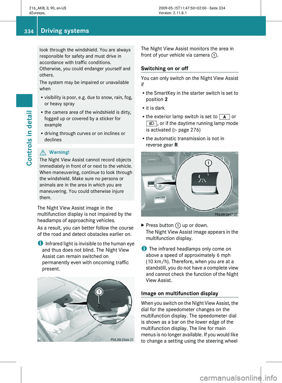
present. The Night View Assist monitors the area in
front of your vehicle via camera
:.
Switching on or off You can only switch on the Night View Assist
if
R
the SmartKey in the starter switch is set to
position 2
R it is dark
R the exterior lamp switch is set to c or
L, or if the daytime running lamp mode
is activated ( Y page 276)
R the automatic transmission is not in
reverse gear R X
Press button : up or down.
The Night View Assist image appears in the
multifunction display.
i The infrared headlamps only come on
above a speed of approximately 6 mph
(10 km/h). Therefore, when you are at a
standstill, you do not have a complete view
and cannot check the function of the Night
View Assist.
Image on multifunction display When you switch on the Night View Assist, the
dial for the speedometer changes on the
multifunction display. The speedometer dial
is shown as a bar on the lower edge of the
multifunction display. The line for main
menus is no longer available. If you would like
to change a setting using the steering wheel334
Driving systemsControls in detail
216_AKB; 3; 90, en-US
d2ureepe,
Version: 2.11.8.1 2009-05-15T11:47:50+02:00 - Seite 334
Page 347 of 500
The rear window defroster uses a large
amount of power. To keep the battery drain
to a minimum, switch off the defroster as
soon as the rear window is clear. The
defroster is switched off automatically after
approximately 6 to 17 minutes of operation
depending on the outside temperature.
X
Switch on the ignition.
X Switching on: Press rocker switch ¤
up or down.
The indicator lamp in the rocker switch
comes on.
X Switching off: Press rocker switch ¤
up or down.
The rear window defroster switches off when
the battery voltage is too low. Too many
electrical consumers may be operating
simultaneously.
X Switch off consumers that are currently not
needed if required. Power tilt/sliding sunroof
Opening and closing
G
Observe Safety notes, see page 51. G
Warning!
When opening or closing the tilt/sliding
sunroof, make sure there is no danger of
anyone being
harmed by the opening/closing
procedure.
The tilt/sliding sunroof is equipped with the
express operation and automatic reversal
function. If the movement of the tilt/sliding
sunroof is blocked during the closing
procedure, the tilt/sliding sunroof will stop
and open slightly.
The tilt/sliding sunroof operates differently
when the sunroof switch is pressed and held.
See the “Closing when the tilt/sliding sunroof
is blocked” section for details.
The opening/closing procedure of the tilt/
sliding sunroof can be immediately halted by
releasing the sunroof switch or, if the sunroof switch was moved past the resistance point
and
released,
by moving the sunroof switch in
any direction. G
Warning!
The tilt/sliding sunroof is made out of glass.
In the event of an accident, the glass may
shatter. This may result in an opening in the
roof.
In a vehicle rollover, occupants not wearing
their seat belts or not wearing them properly
may be thrown out of the opening. Such an
opening also
presents a potential for injury for
occupants wearing their seat belts properly as
entire body parts or portions of them may
protrude from the passenger compartment.
! To avoid damaging the seals, do not
transport any objects with sharp edges
which can stick out of the tilt/sliding
sunroof.
Do not open the tilt/sliding sunroof if there
is snow or ice on the roof, as this could
result in malfunctions.
If you cannot open or close the tilt/sliding
sunroof due to a malfunction contact
Roadside Assistance or an authorized
Mercedes-Benz Center.
! Please keep in mind that weather
conditions can sometimes change rapidly.
Make sure to close the tilt/sliding sunroof
when leaving the vehicle. If water enters
the vehicle interior, vehicle electronics
could be damaged which is not covered by
the Mercedes-Benz Limited Warranty.
i You can also open or close the tilt/sliding
sunroof using the SmartKey or the
KEYLESS-GO function, see “Summer
opening feature” ( Y page 283) and
“Convenience closing feature”
(Y page 284).
i After switching off the ignition or
removing the SmartKey from the starter
switch, you can operate the tilt/sliding Power tilt/sliding sunroof
345
Controls in detail
216_AKB; 3; 90, en-US
d2ureepe, Version: 2.11.8.1 2009-05-15T11:47:50+02:00 - Seite 345 Z
Page 351 of 500
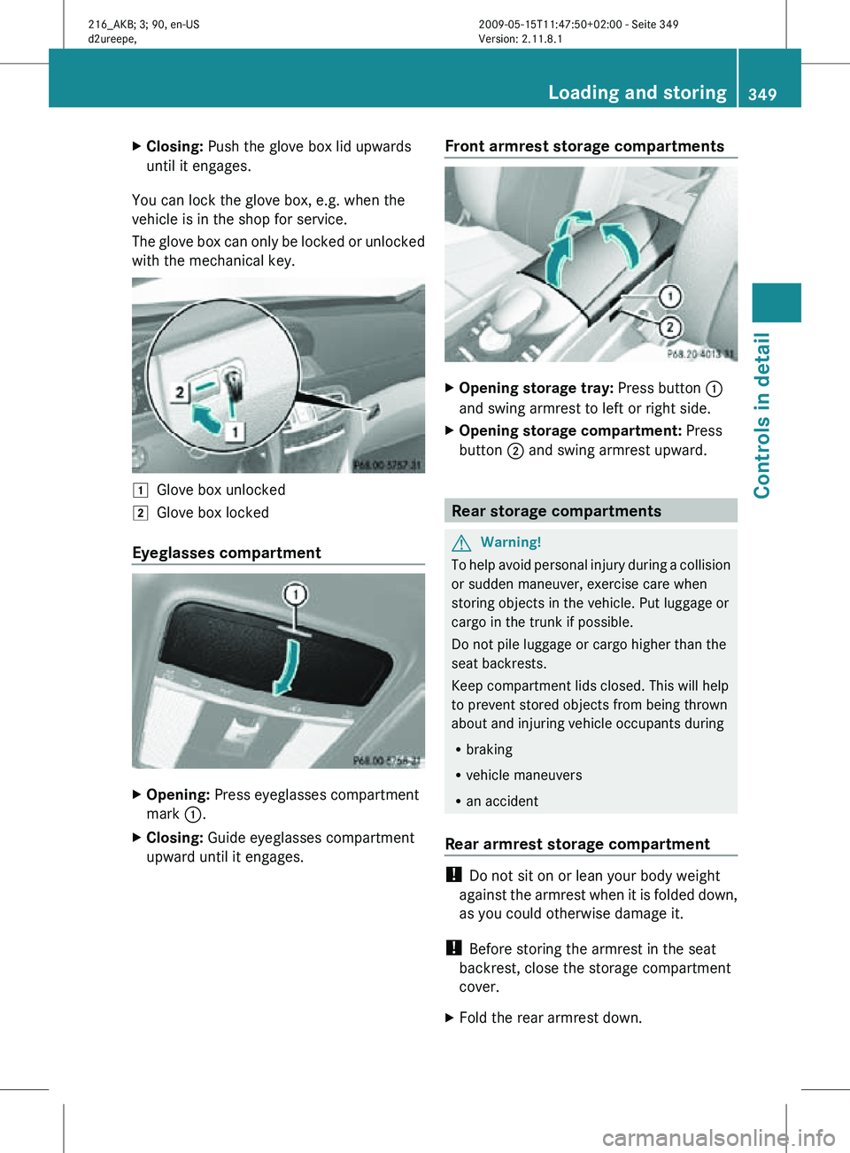
X
Closing: Push the glove box lid upwards
until it engages.
You can lock the glove box, e.g. when the
vehicle is in the shop for service.
The glove box can only be locked or unlocked
with the mechanical key. 1
Glove box unlocked
2 Glove box locked
Eyeglasses compartment X
Opening: Press eyeglasses compartment
mark :.
X Closing: Guide eyeglasses compartment
upward until it engages. Front armrest storage compartments X
Opening storage tray: Press button :
and swing armrest to left or right side.
X Opening storage compartment: Press
button ; and swing armrest upward. Rear storage compartments
G
Warning!
To help avoid personal injury during a collision
or sudden maneuver, exercise care when
storing objects in the vehicle. Put luggage or
cargo in the trunk if possible.
Do not pile luggage or cargo higher than the
seat backrests.
Keep compartment lids closed. This will help
to prevent stored objects from being thrown
about and injuring vehicle occupants during
R braking
R vehicle maneuvers
R an accident
Rear armrest storage compartment !
Do not sit on or lean your body weight
against the armrest when it is folded down,
as you could otherwise damage it.
! Before storing the armrest in the seat
backrest, close the storage compartment
cover.
X Fold the rear armrest down. Loading and storing
349Controls in detail
216_AKB; 3; 90, en-US
d2ureepe, Version: 2.11.8.1 2009-05-15T11:47:50+02:00 - Seite 349 Z
Page 358 of 500
X
Wait for a voice connection to the
Customer Assistance Center.
X Close cover ; after the emergency call is
concluded. G
Warning!
If you feel at any way in jeopardy when in the
vehicle (e.g. smoke or fire in the vehicle,
vehicle in a dangerous road location), please
do not wait for voice contact after you have
pressed the emergency button. Carefully
leave the vehicle and move to a safe location.
The Customer Assistance Center will
automatically contact local emergency
officials with the vehicle’s approximate
location if they receive an automatic SOS
signal and cannot make voice contact with the
vehicle occupants.
X Terminating calls: Press button ~ on
the multifunction steering wheel.
or
X Press the respective button for ending a
telephone call on the telephone keypad.
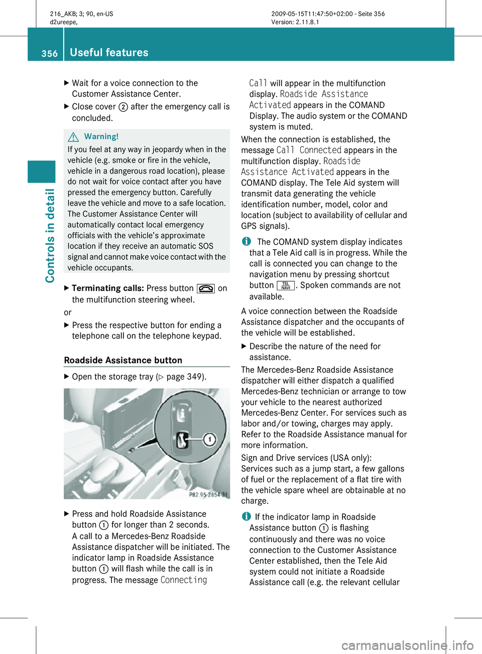
Roadside Assistance button X
Open the storage tray (Y page 349). X
Press and hold Roadside Assistance
button : for longer than 2 seconds.
A call to a Mercedes-Benz Roadside
Assistance dispatcher will be initiated. The
indicator lamp in Roadside Assistance
button : will flash while the call is in
progress. The message Connecting Call will appear in the multifunction
display.
Roadside Assistance
Activated appears in the COMAND
Display. The audio system or the COMAND
system is muted.
When the connection is established, the
message Call Connected appears in the
multifunction display. Roadside
Assistance Activated appears in the
COMAND display. The Tele Aid system will
transmit data generating the vehicle
identification number, model, color and
location (subject to availability of cellular and
GPS signals).
i The COMAND system display indicates
that a Tele Aid call is in progress. While the
call is connected you can change to the
navigation menu by pressing shortcut
button S. Spoken commands are not
available.
A voice connection between the Roadside
Assistance dispatcher and the occupants of
the vehicle will be established.
X Describe the nature of the need for
assistance.
The Mercedes-Benz Roadside Assistance
dispatcher will either dispatch a qualified
Mercedes-Benz technician or arrange to tow
your vehicle to the nearest authorized
Mercedes-Benz Center. For services such as
labor and/or towing, charges may apply.
Refer to the Roadside Assistance manual for
more information.
Sign and Drive services (USA only):
Services such as a jump start, a few gallons
of fuel or the replacement of a flat tire with
the vehicle spare wheel are obtainable at no
charge.
i If the indicator lamp in Roadside
Assistance button : is flashing
continuously and there was no voice
connection to the Customer Assistance
Center established, then the Tele Aid
system could not initiate a Roadside
Assistance call (e.g. the relevant cellular 356
Useful featuresControls in detail
216_AKB; 3; 90, en-US
d2ureepe,
Version: 2.11.8.1 2009-05-15T11:47:50+02:00 - Seite 356
Page 359 of 500
phone network is not available). The
message
Call Failed appears in the
multifunction display. Call could not
be connected! appears in the COMAND
display. Confirm the message pressing W
(Y page 71).
X Terminating calls: Press button ~ on
the multifunction steering wheel.
or
X Press the respective button for ending a
telephone call on the telephone keypad.
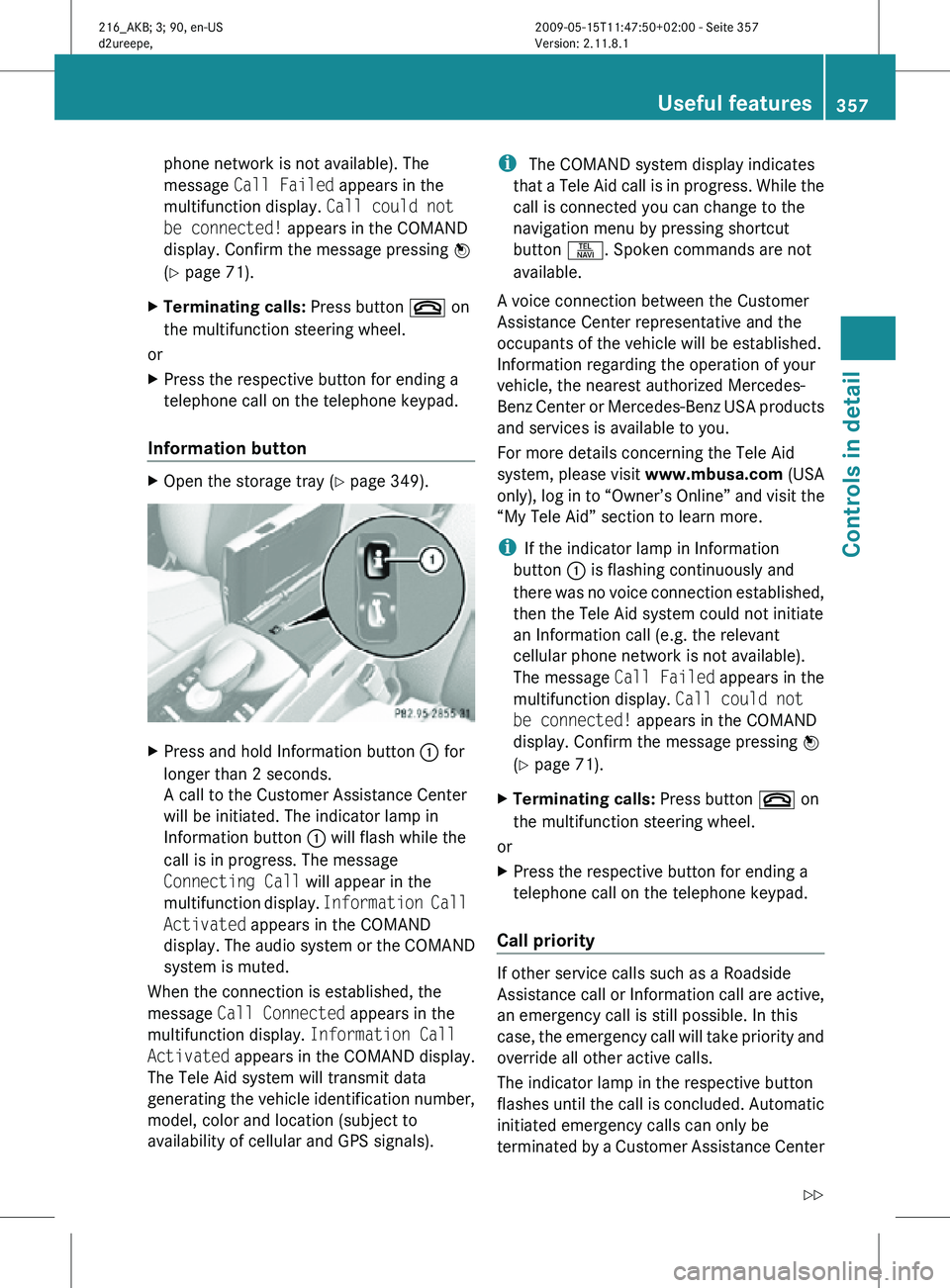
Information button X
Open the storage tray (Y page 349). X
Press and hold Information button : for
longer than 2 seconds.
A call to the Customer Assistance Center
will be initiated. The indicator lamp in
Information button : will flash while the
call is in progress. The message
Connecting Call will appear in the
multifunction display. Information Call
Activated appears in the COMAND
display. The audio system or the COMAND
system is muted.
When the connection is established, the
message Call Connected appears in the
multifunction display. Information Call
Activated appears in the COMAND display.
The Tele Aid system will transmit data
generating the vehicle identification number,
model, color and location (subject to
availability of cellular and GPS signals). i
The COMAND system display indicates
that a Tele Aid call is in progress. While the
call is connected you can change to the
navigation menu by pressing shortcut
button S. Spoken commands are not
available.
A voice connection between the Customer
Assistance Center representative and the
occupants of the vehicle will be established.
Information regarding the operation of your
vehicle, the nearest authorized Mercedes-
Benz Center or Mercedes-Benz USA products
and services is available to you.
For more details concerning the Tele Aid
system, please visit www.mbusa.com (USA
only), log in to “Owner’s Online” and visit the
“My Tele Aid” section to learn more.
i If the indicator lamp in Information
button : is flashing continuously and
there was no voice connection established,
then the Tele Aid system could not initiate
an Information call (e.g. the relevant
cellular phone network is not available).
The message Call Failed appears in the
multifunction display. Call could not
be connected! appears in the COMAND
display. Confirm the message pressing W
(Y page 71).
X Terminating calls: Press button ~ on
the multifunction steering wheel.
or
X Press the respective button for ending a
telephone call on the telephone keypad.
Call priority If other service calls such as a Roadside
Assistance call or Information call are active,
an emergency call is still possible. In this
case, the emergency call will take priority and
override all other active calls.
The indicator lamp in the respective button
flashes until the call is concluded. Automatic
initiated emergency calls can only be
terminated by a Customer Assistance Center Useful features
357Controls in detail
216_AKB; 3; 90, en-US
d2ureepe, Version: 2.11.8.1 2009-05-15T11:47:50+02:00 - Seite 357 Z
Page 360 of 500
representative. All other calls can be
terminated by pressing button ~ on the
multifunction steering wheel or the
respective
button
for ending a telephone call
on the telephone keypad.
Destination Download to the COMAND
system i
The components
and operating principles
of the COMAND system can be found on
(Y page 69).
Destination Download allows you access to a
database of over 10 million points of interest
(POIs) that can be downloaded to your
vehicle’s navigation system. If you know the
destination, the address can be downloaded,
or can be provided with points of interests
near your location.
Route guidance
You will be prompted to confirm that route
guidance to the entered address is to be
started.
X Slide ZVÆ or rotate cVd to select Yes
menu item and confirm by pressing W.
The system calculates the route and
subsequently starts
the route guidance to the
defined address.
i If you select No, you can save the address
to your address book.
i The Destination Download feature is
available if the relevant mobile phone
network is available and data connection is
possible.
Search & Send i
In order to utilize Search & Send your
vehicle must be equipped with Tele Aid,
Navigation, and an active Tele Aid
subscription.
“Search & Send” is a navigation destination
address entry service. A destination address
located using Google Maps ®
or Yahoo Local Maps
®
websites can be delivered via Tele Aid
directly to the Navigation system in your
vehicle.
Specify and Send a Destination Address
i Please refer to any specific instructions
provided by either website regarding
entering or sending an address. Each
website
functions differently and is subject
to change.
X Go to www.maps.google.com or
www.maps.yahoo.com and enter a
destination address in the address entry
field.
X Depending on which website you are using,
click on
the appropriate button to send the
destination address to your Tele Aid
account email address.
X Enter the email address you specified when
you activated your Tele Aid account in the
appropriate field when the “Send” dialog
box appears.
X Click “Send”.
Retrieve Destination Address
X Press the Tele Aid Information button to
begin the download of the destination
address to your vehicle's navigation
system.
i If you have sent more than one
destination address to your vehicle you
must make one Information call for each
destination address download.
X Select Yes when the message appears
asking if
you would like to start navigation.
This will open the start navigation screen.
X Select Start.
or
X Select No if you wish to save the
downloaded destination address in the
From Memory destination list for future
use. 358
Useful features
Controls in detail
216_AKB; 3; 90, en-US
d2ureepe,
Version: 2.11.8.1 2009-05-15T11:47:50+02:00 - Seite 358