MERCEDES-BENZ CL COUPE 2009 Owner's Guide
Manufacturer: MERCEDES-BENZ, Model Year: 2009, Model line: CL COUPE, Model: MERCEDES-BENZ CL COUPE 2009Pages: 421, PDF Size: 10.78 MB
Page 31 of 421
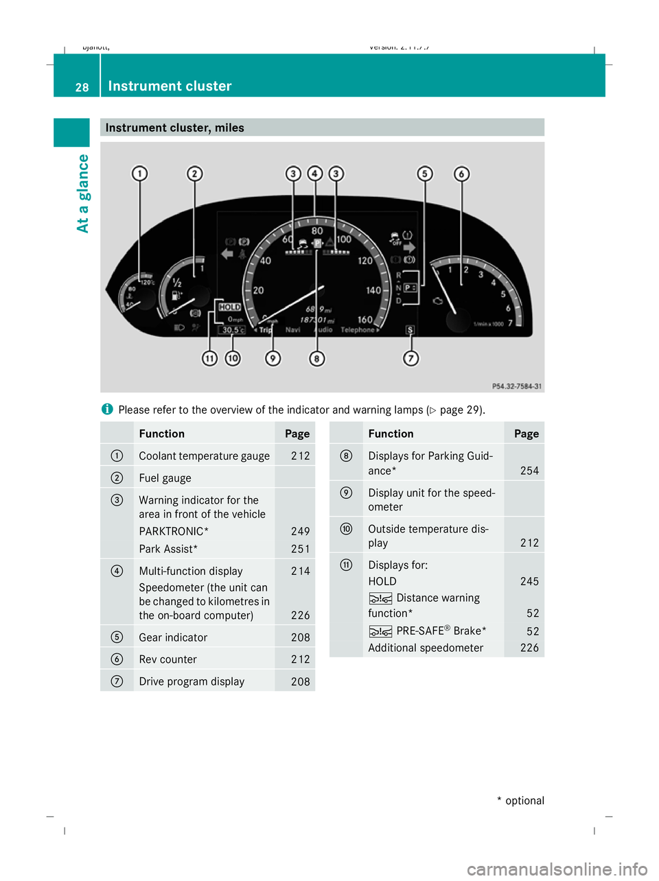
Instrument cluster, miles
i
Please refer to the overview of the indicator and warning lamps ( Ypage 29). Function Page
:
Coolant temperature gauge 212
;
Fuel gauge
=
Warning indicator for the
area in front of the vehicle
PARKTRONIC* 249
Park Assist* 251
?
Multi-function display 214
Speedometer (the unit can
be changed to kilometres in
the on-board computer)
226
A
Gear indicator 208
B
Rev counter 212
C
Drive program display
208 Function Page
D
Displays for Parking Guid-
ance*
254
E
Display unit for the speed-
ometer
F
Outside temperature dis-
play
212
G
Displays for:
HOLD 245
Ä
Distance warning
function* 52
Ä
PRE-SAFE ®
Brake* 52
Additional speedometer 22628
Instrument clusterAt a glance
* optional
216_AKB; 2; 3, en-GB
bjanott
,V ersion: 2.11.7.7
2009-02-27T14:54:17+01:00 - Seite 28
Dateiname: 6515230602_buchblock.pdf; erzeugt am 04. Mar 2009 11:14:41; WK
Page 32 of 421
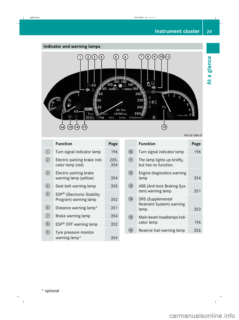
Indicator and warning lamps
Function Page
:
Turn signal indicator lamp 196
;
Electric parking brake indi-
cator lamp (red) 205,
354 =
Electric parking brake
warning lamp (yellow)
354
?
Seat belt warning lamp 355
A
ESP
®
(Electronic Stability
Program) warning lamp 352
B
Distance warning lamp* 351
C
Brake warning lamp 354
D
ESP
®
OFF warning lamp 352
E
Tyre pressure monitor
warning lamp*
354 Function Page
F
Turn signal indicator lamp 196
G
The lamp lights up briefly,
but has no function.
H
Engine diagnostics warning
lamp 354
I
ABS (Anti-lock Braking Sys-
tem) warning lamp
351
J
SRS (Supplemental
Restraint System) warning
lamp 353
K
Main-beam headlamps indi-
cator lamp 196
L
Reserve fuel warning lamp 356Instrument cluster
29At a glance
* optional
216_AKB; 2; 3, en-GB
bjanott
,V ersion: 2.11.7.7
2009-02-27T14:54:17+01:00 - Seite 29 Z
Dateiname: 6515230602_buchblock.pdf; erzeugt am 04. Mar 2009 11:14:41; WK
Page 33 of 421
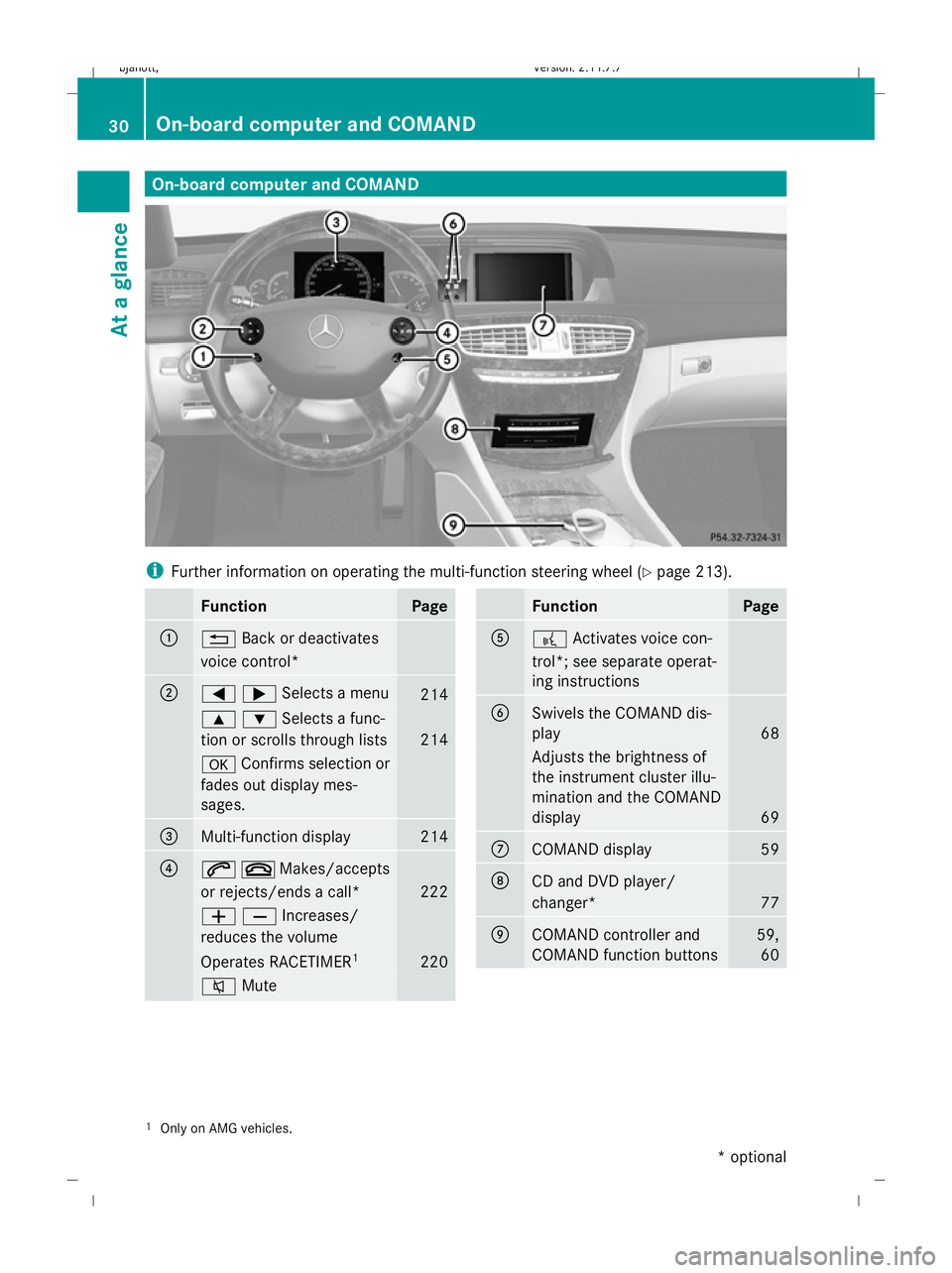
On-board computer and COMAND
i
Further information on operating the multi-function steering wheel (Y page 213).Function Page
:
%
Back or deactivates
voice control* ;
=;Selects a menu
214
9:Selects a func-
tion or scrolls through lists 214
a
Confirms selection or
fades out display mes-
sages. =
Multi-function display 214
?
6~Makes/accepts
or rejects/ends a call* 222
WXIncreases/
reduces the volume Operates RACETIMER
1 220
8
Mute Function Page
A
?
Activates voice con-
trol*; see separate operat-
ing instructions B
Swivels the COMAND dis-
play
68
Adjusts the brightness of
the instrument cluster illu-
mination and the COMAND
display
69
C
COMAND display 59
D
CD and DVD player/
changer*
77
E
COMAND controller and
COMAND function buttons 59,
60 1
Only on AMG vehicles. 30
On-board computer and COMANDAt a glance
* optional
216_AKB; 2; 3, en-GB
bjanott,
Version: 2.11.7.7
2009-02-27T14:54:17+01:00 - Seite 30
Dateiname: 6515230602_buchblock.pdf; erzeugt am 04. Mar 2009 11:14:42; WK
Page 34 of 421
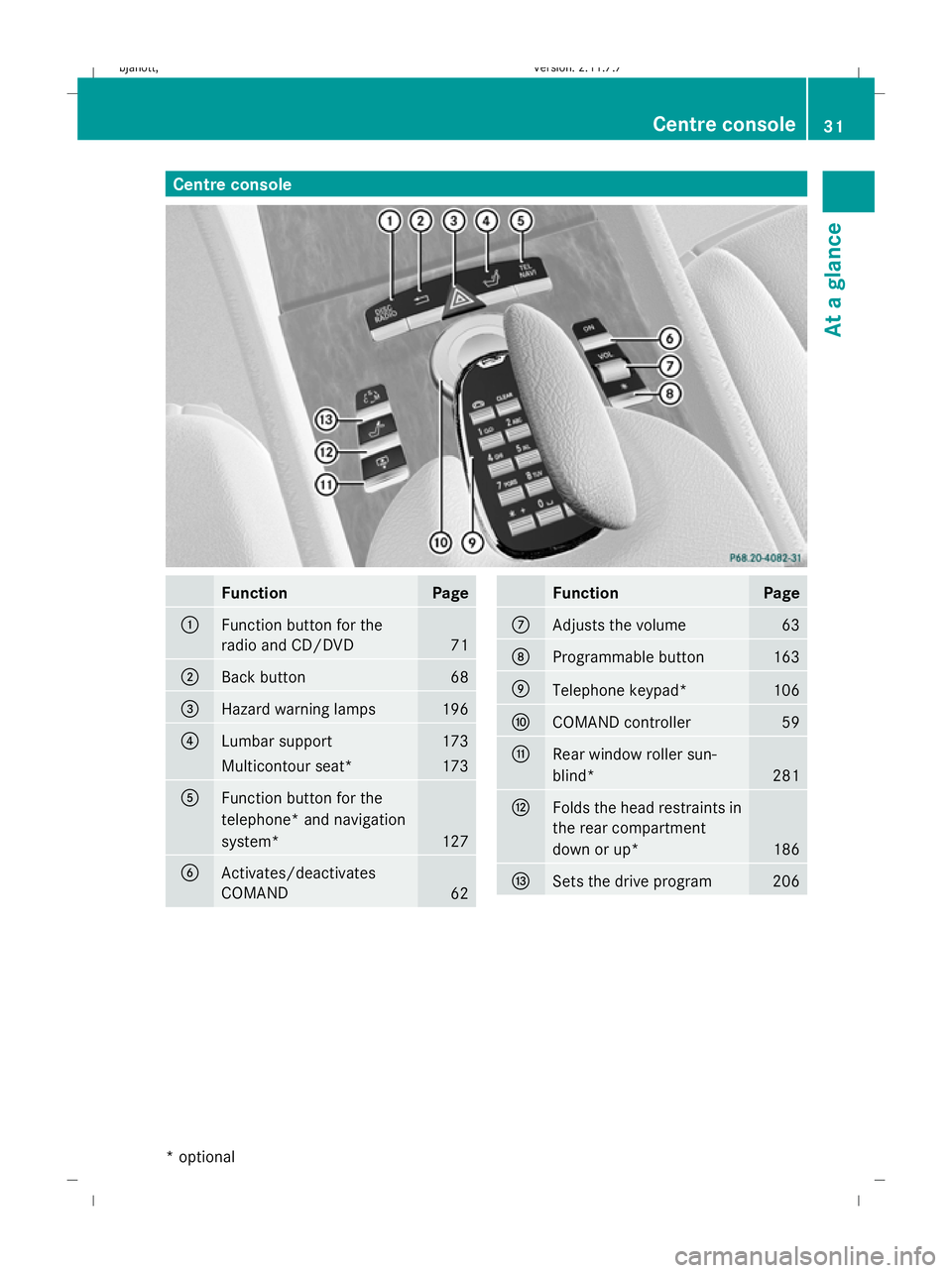
Centre console
Function Page
:
Function button for the
radio and CD/DVD
71
;
Back button 68
=
Hazard warning lamps 196
?
Lumbar support 173
Multicontour seat* 173
A
Function button for the
telephone* and navigation
system*
127
B
Activates/deactivates
COMAND
62 Function Page
C
Adjusts the volume 63
D
Programmable button 163
E
Telephone keypad* 106
F
COMAND controller 59
G
Rear window roller sun-
blind*
281
H
Folds the head restraints in
the rear compartment
down or up* 186
I
Sets the drive program 206Centre console
31At a glance
* optional
216_AKB; 2; 3, en-GB
bjanott
,V ersion: 2.11.7.7
2009-02-27T14:54:17+01:00 - Seite 31 Z
Dateiname: 6515230602_buchblock.pdf; erzeugt am 04. Mar 2009 11:14:43; WK
Page 35 of 421
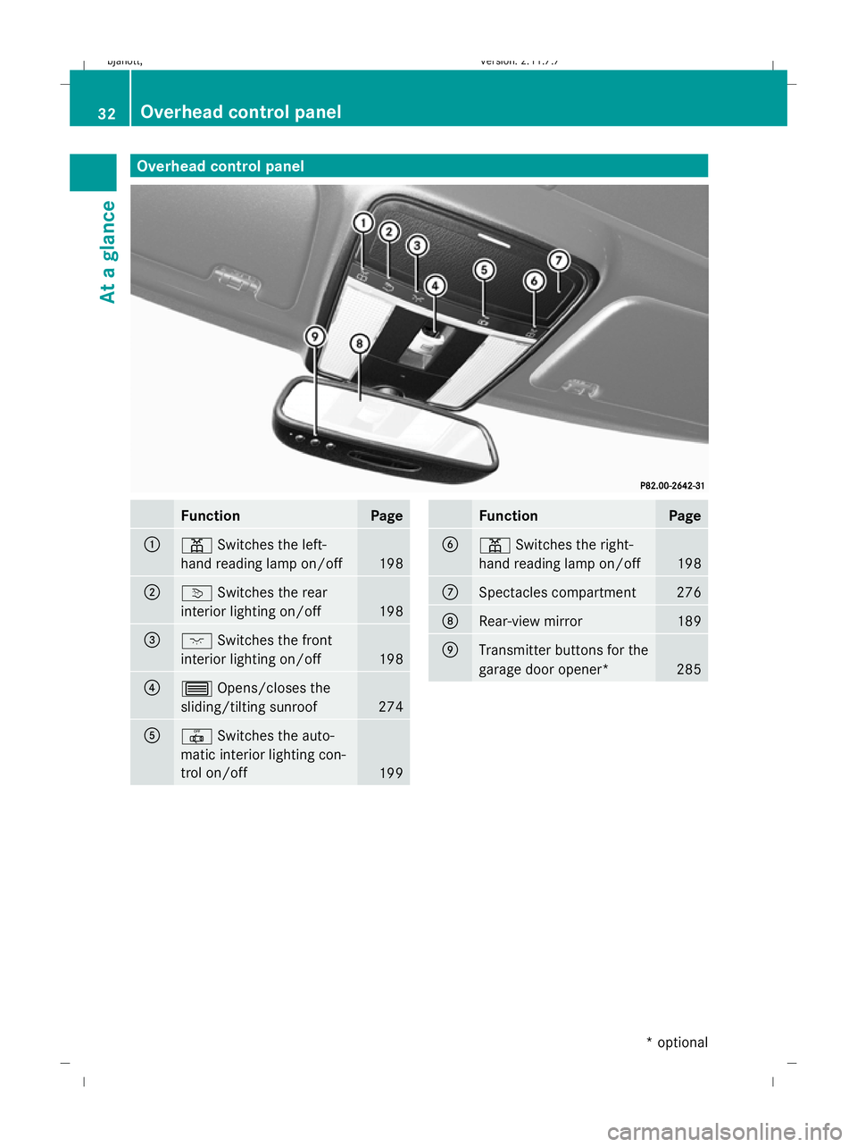
Overhead control panel
Function Page
:
p
Switches the left-
hand reading lamp on/off 198
;
v
Switches the rear
interior lighting on/off 198
=
c
Switches the front
interior lighting on/off 198
?
3
Opens/closes the
sliding/tilting sunroof 274
A
|
Switches the auto-
matic interior lighting con-
trol on/off 199 Function Page
B
p
Switches the right-
hand reading lamp on/off 198
C
Spectacles compartment 276
D
Rear-view mirror 189
E
Transmitter buttons for the
garage door opener*
28532
Overhead control panelAt a glance
* optional
216_AKB; 2; 3, en-GB
bjanott,
Version: 2.11.7.7 2009-02-27T14:54:17+01:00 - Seite 32
Dateiname: 6515230602_buchblock.pdf; erzeugt am 04. Mar 2009 11:14:44; WK
Page 36 of 421
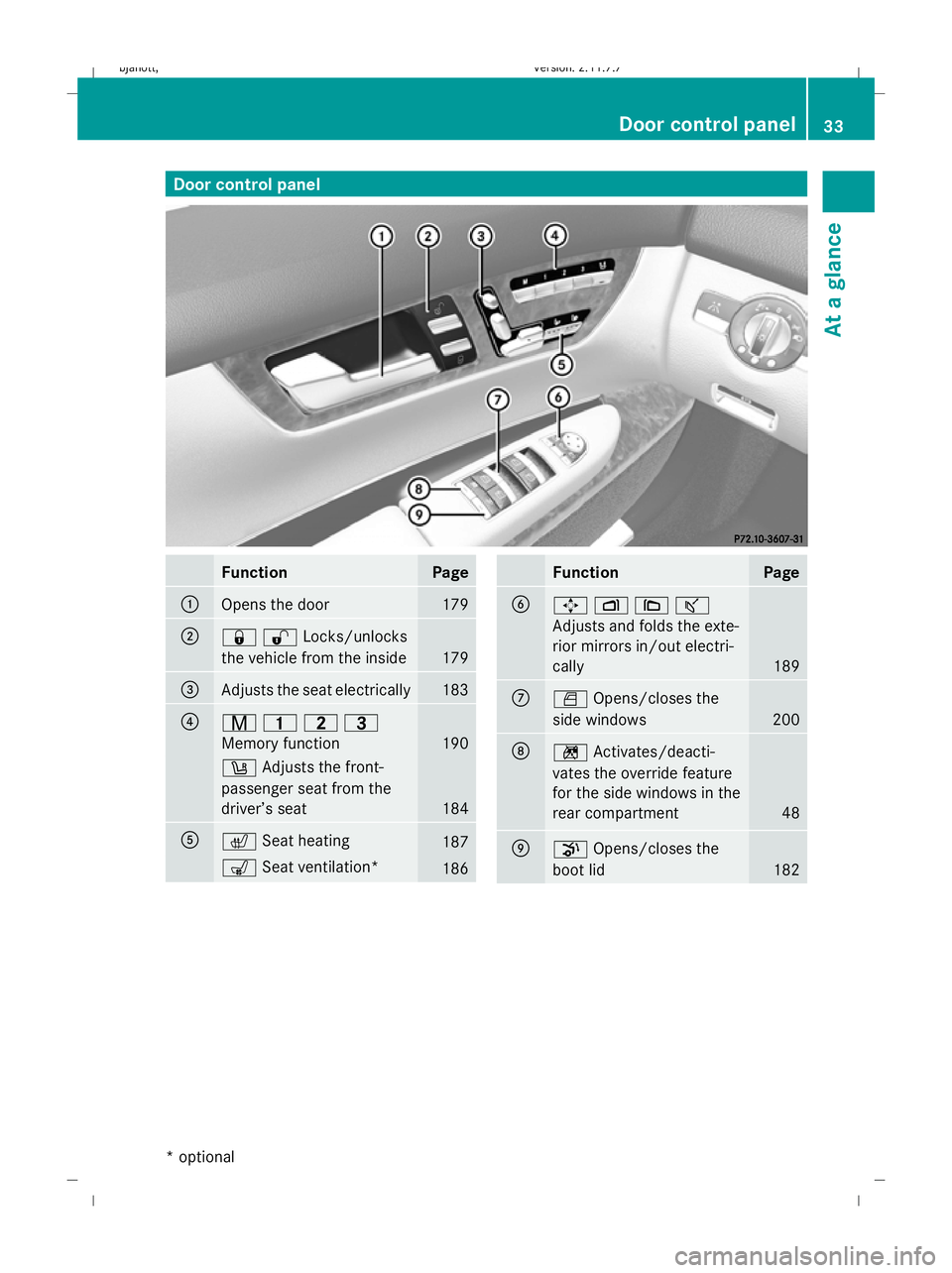
Door control panel
Function Page
:
Opens the door 179
;
&%Locks/unlocks
the vehicle from the inside 179
=
Adjusts the seat electrically 183
?
r
45=
Memory function 190
w
Adjusts the front-
passenger seat from the
driver’s seat 184
A
c
Seat heating 187
s
Seat ventilation* 186 Function Page
B
7
Z\ª
Adjusts and folds the exte-
rior mirrors in/out electri-
cally 189
C
W
Opens/closes the
side windows 200
D
n
Activates/deacti-
vates the override feature
for the side windows in the
rear compartment 48
E
p
Opens/closes the
boot lid 182Door control panel
33At a glance
* optional
216_AKB; 2; 3, en-GB
bjanott,
Version: 2.11.7.7 2009-02-27T14:54:17+01:00 - Seite 33 Z
Dateiname: 6515230602_buchblock.pdf; erzeugt am 04. Mar 2009 11:14:45; WK
Page 37 of 421

34 216_AKB; 2; 3, en-GB
bjanott,
Version: 2.11.7.7 2009-02-27T14:54:17+01:00 - Seite 34Dateiname: 6515230602_buchblock.pdf; erzeugt am 04. Mar 2009 11:14:45; WK
Page 38 of 421
Occupant safety
.................................. 36
Driving safety systems .......................48
Anti-theft systems .............................. 54 35Safety
216_AKB; 2; 3, en-GB
bjanott,
Version: 2.11.7.7 2009-02-27T14:54:17+01:00 - Seite 35
Dateiname: 6515230602_buchblock.pdf; erzeugt am 04. Mar 2009 11:14:46; WK
Page 39 of 421
Occupant safety
Notes on occupant safety
Seat belts, together with belt tensioners, belt
force limiters and airbags, are complemen-
tary, coordinated restraint systems. They
reduce the risk of injury in specific, pre-
defined types of accident situations and,
thereby, increase occupant safety. However,
seat belts and airbags generally do not pro-
tect against objects penetrating the vehicle
from the outside.
To ensure that the restraint systems can
deliver their full potential protection, you
should ensure that:
R the seat and head restraint are adjusted
properly (Y page 183).
R the seat belt has been fastened properly
(Y page 191).
R the airbags can inflate properly if they are
deployed (Y page 39).
R the steering wheel is adjusted properly
(Y page 187).
R the restraint systems have not been modi-
fied.
i An airbag increases the protection of
vehicle occupants wearing a seat belt.
However, airbags are only an additional
restraint system which complements, but
does not replace, the seat belt. All vehicle
occupants must wear their seat belt cor-
rectly at all times, even if the vehicle is
equipped with airbags. This is because – on
the one hand – airbags are not deployed in
all types of accident, as in some situations
airbag deployment would not increase the
protection afforded to vehicle occupants,
provided they are wearing their seat belt
correctly. On the other hand, airbag deploy-
ment only provides increased protection if
the seat belt is worn correctly because: R
the seat belt helps to keep the vehicle
occupant in the best position in relation
to the airbag.
R for example, in a head-on collision, the
seat belt can more adequately prevent
the occupant from being propelled
towards the point of the impact, and is
thus better suited to prevent injury.
Therefore, in accident situations where an
airbag is deployed, it only provides protec-
tion in addition to the seat belt if the seat
belt is being worn correctly. G
Risk of accident and injury
Always have maintenance work carried out at
a qualified specialist workshop which has the
necessary specialist knowledge and tools to
carry out the work required.
Mercedes-Benz recommends that you use a
Mercedes-Benz Service Centre for this pur-
pose.
In particular, work relevant to safety or on
safety-related systems must be carried out at
a qualified specialist workshop. If this work is
not carried out correctly, the operating safety
of your vehicle may be affected. There is a risk
of an accident and injury. G
Risk of injury
Modifications to or work performed incor-
rectly on the following parts can result in the
restraint systems not functioning as intended:
R the restraint system, consisting of seat
belts and their anchorage points, belt ten-
sioners, belt force limiters and airbags
R the wiring
R any networked electronic systems
Airbags and belt tensioners could fail, e.g. in
the event of an accident, the deceleration
force of which would normally be sufficient to
trigger the systems, or could be triggered
unintentionally. For this reason, never make
any modifications to the restraint systems. 36
Occupant safetySafety
216_AKB; 2; 3, en-GB
bjanott,
Version: 2.11.7.7 2009-02-27T14:54:17+01:00 - Seite 36
Dateiname: 6515230602_buchblock.pdf; erzeugt am 04. Mar 2009 11:14:46; WK
Page 40 of 421
You must not tamper with electronic compo-
nents or their software.
SRS (Supplemental Restraint System)
The SRS reduces the risk of occupants com-
ing into contact with the vehicle's interior in
the event of an accident. It can also reduce
the forces to which occupants are subjected
during an accident.
The SRS consists of:
R The 6 SRS warning lamp
R belt tensioners
R belt force limiters
R airbags
The 6 6 SRS warning lamp SRS functions are checked regularly when
you turn on the ignition and when the engine
is running. Therefore, malfunctions can be
detected in good time.
The 6 SRS warning lamp in the instrument
cluster lights up when the ignition is switched
on. It goes out no later than a few seconds
after the engine is started. G
Risk of injury
If SRS is malfunctioning, individual systems
may be activated unintentionally or not be
deployed in the event of an accident with
heavy braking.
A malfunction has occurred if the 6SRS
warning lamp:
R does not light up when you switch on the
ignition
R does not go out after the engine has been
running for a few seconds
R lights up again once the engine is running
In this case, have SRS checked immediately
at a qualified specialist workshop. Triggering of belt tensioners, belt force
limiters and airbags In the event of a collision, the sensor in the
airbag control unit evaluates important phys-
ical data such as duration, direction and force
of the vehicle deceleration or acceleration.
Based on the evaluation of this data and
depending on the vehicle's rate of longitudi-
nal deceleration in a collision, in the first
stage the airbag control unit pre-emptively
triggers the belt tensioners.
i
The front belt tensioners can only be trig-
gered if the belt tongue is correctly
engaged in the seat belt buckle.
The front airbags are only deployed if there is
an even higher rate of vehicle deceleration in
a longitudinal direction.
Your vehicle has adaptive, dual stage front
airbags. When the first activation threshold is
reached, the front airbag is filled with enough
propellant gas to reduce the risk of injuries.
The front airbag is only fully inflated if a sec-
ond threshold is reached within a few milli-
seconds, due to the control unit having detec-
ted further deceleration.
Criteria for triggering belt tensioners and
airbags
In the first stage of a collision, the airbag con-
trol unit evaluates the duration and direction
of vehicle acceleration or deceleration in
order to determine whether it is necessary to
trigger the belt tensioner and/or airbag.
The belt tensioner and airbag triggering
thresholds are variable and are adapted to the
rate of deceleration of the vehicle. This proc-
ess is pre-emptive in nature as the airbag
must be deployed during – and not at the end
of – the collision.
i Airbags are not deployed in all types of
accidents. They are controlled by complex
sensor technology and evaluation logic.
This process is pre-emptive in nature as
airbag deployment must take place during
the impact and must be adapted to provide Occupant safety
37Safety
216_AKB; 2; 3, en-GB
bjanott,V ersion: 2.11.7.7
2009-02-27T14:54:17+01:00 - Seite 37 Z
Dateiname: 6515230602_buchblock.pdf; erzeugt am 04. Mar 2009 11:14:46; WK