tow MERCEDES-BENZ CL COUPE 2009 Repair Manual
[x] Cancel search | Manufacturer: MERCEDES-BENZ, Model Year: 2009, Model line: CL COUPE, Model: MERCEDES-BENZ CL COUPE 2009Pages: 421, PDF Size: 10.78 MB
Page 381 of 421
To reduce the tyre pressure:
press pres-
sure release button Enext to pressure
gauge F.
X Drive to the nearest workshop and have the
tyre changed there.
X Have the TIREFIT kit replaced as soon as
possible at a qualified specialist workshop,
e.g. at a Mercedes-Benz Service Centre. G
Risk of accident
Do not exceed the maximum speed of
80 km/h.
The "max. 80 km/h" label must be affixed in
the driver's field of vision.
The vehicle's handling characteristics may be
affected. H
Environmental note
Have the used TIREFIT kit disposed of profes-
sionally, e.g. at a Mercedes-Benz Service
Centre.
X Have the TIREFIT kit replaced every four
years at a qualified specialist workshop,
e.g. a Mercedes-Benz Service Centre. Changing a wheel and fitting the
spare wheel*
G
Risk of accident
The wheel dimensions and tyre size of the
"Minispare" emergency spare wheel *are dif-
ferent from those of the damaged wheel.
Your vehicle's handling characteristics will
change when a "Minispare" emergency spare
wheel* is fitted. Adapt your style of driving
accordingly.
The "Minispare" emergency spare wheel*
may only be used for a short time. Do not
exceed the maximum speed of 80 km/h and
do not deactivate ESP ®
.
Never drive the vehicle with more than one
"Minispare" emergency spare wheel* fitted. G
Risk of accident
Have the "Minispare" emergency spare
wheel* or the spare wheel* replaced with a
new wheel as soon as possible at a qualified
specialist workshop which has the necessary
specialist knowledge and tools to carry out
the work required. Mercedes-Benz recom-
mends that you use a Mercedes-Benz Service
Centre for this purpose. In particular, work
relevant to safety or on safety-related sys-
tems must be carried out at a qualified spe-
cialist workshop.
Preparing the vehicle X
Prepare the vehicle as described
(Y page 373).
X Place the wheels in the straight-ahead posi-
tion.
X Remove the following items from the stow-
age well under the boot floor:
R
the "Minispare" emergency spare
wheel* or the spare wheel*
R the container with the wheel bolts for the
"Minispare" emergency spare wheel* or
the spare wheel*
R the vehicle tool kit
R the wheel chock
R the jack
X Secure the vehicle to prevent it from rolling
away.
On level ground: place chocks or similar
items under the front and rear of the wheel
that is diagonally opposite the wheel you
wish to change.
X On downhill gradients: place chocks or
similar items behind the wheels of the front
and rear axle. 378
Flat tyrePractical advice
* optional
216_AKB; 2; 3, en-GB
bjanott,
Version: 2.11.7.7 2009-02-27T14:54:17+01:00 - Seite 378
Dateiname: 6515230602_buchblock.pdf; erzeugt am 04. Mar 2009 11:16:49; WK
Page 384 of 421
X
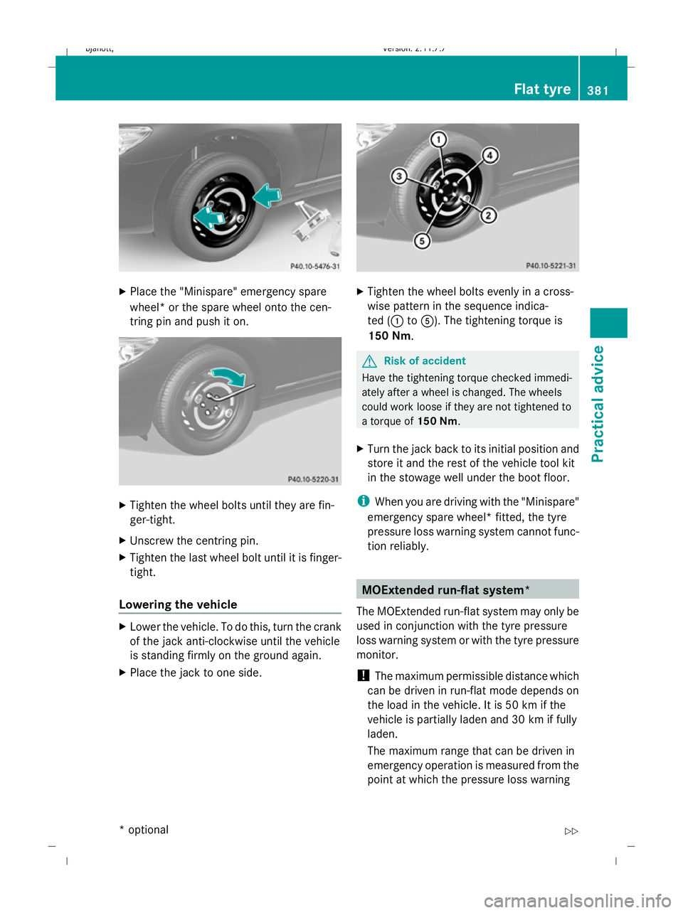
Place the "Minispare" emergency spare
wheel* or the spare wheel onto the cen-
tring pin and push it on. X
Tighten the wheel bolts until they are fin-
ger-tight.
X Unscrew the centring pin.
X Tighten the last wheel bolt until it is finger-
tight.
Lowering the vehicle X
Lower the vehicle. To do this, turn the crank
of the jack anti-clockwise until the vehicle
is standing firmly on the ground again.
X Place the jack to one side. X
Tighten the wheel bolts evenly in a cross-
wise pattern in the sequence indica-
ted (: toA). The tightening torque is
150 Nm. G
Risk of accident
Have the tightening torque checked immedi-
ately after a wheel is changed. The wheels
could work loose if they are not tightened to
a torque of 150 Nm.
X Turn the jack back to its initial position and
store it and the rest of the vehicle tool kit
in the stowage well under the boot floor.
i When you are driving with the "Minispare"
emergency spare wheel* fitted, the tyre
pressure loss warning system cannot func-
tion reliably. MOExtended run-flat system*
The MOExtended run-flat system may only be
used in conjunction with the tyre pressure
loss warning system or with the tyre pressure
monitor.
! The maximum permissible distance which
can be driven in run-flat mode depends on
the load in the vehicle. It is 50 km if the
vehicle is partially laden and 30 km if fully
laden.
The maximum range that can be driven in
emergency operation is measured from the
point at which the pressure loss warning Flat tyre
381Practical advice
* optional
216_AKB; 2; 3, en-GB
bjanott,
Version: 2.11.7.7 2009-02-27T14:54:17+01:00 - Seite 381 Z
Dateiname: 6515230602_buchblock.pdf; erzeugt am 04. Mar 2009 11:16:51; WK
Page 389 of 421
ger. If necessary, depress the brake pedal
with maximum force.
R you can no longer turn the key in the igni-
tion lock and, on vehicles with KEYLESS
GO*, pressing the start/stop button will
have no effect.
R the selector lever is locked in position P.
! Always disconnect the battery in
the order described below. Never swap the
terminal clamps. Otherwise, you may dam-
age the vehicle electronics.
i On vehicles with KEYLESS GO*: pull the
start/stop button out (Y page 183) and use
the key with KEYLESS GO like the normal
key.
Disconnecting the battery X
Use the electric parking brake to secure the
vehicle and use the DIRECT SELECT lever
to set the transmission to P.
X Switch off all electrical consumers.
X Turn the key to position 0in the ignition
lock and remove it.
X Open the bonnet.
X Remove the negative terminal clamp from
the battery.
X Remove the cover from the positive termi-
nal.
X Remove the positive terminal clamp from
the battery.
X Disconnect the breather hose.
Removing the battery X
Loosen the brackets which hold the battery
in place and remove the battery. Fitting and connecting the battery
Fitting the battery X
Insert the battery into the battery case.
X Secure the battery with the bracket in the
battery case.
Reconnecting the battery !
Always reconnect the battery in the
sequence described below. Never swap the
terminal clamps. You may otherwise dam-
age the vehicle electronics.
X Switch off all electrical consumers.
X Connect the positive terminal clamp and
secure the cover.
X Connect the negative terminal clamp.
X Connect the breather hose. Make sure that
a cell cap is fitted between the battery and
the breather hose.
X Close the bonnet. Towing and tow-starting
Points to remember
G
Risk of accident
If you have the vehicle towed, you must use a
rigid towing bar if:
R the engine is not running.
R there is a brake system malfunction.
R there is a malfunction in the power supply
or the vehicle's electrical system.
The power steering and the brake force boos-
ter do not work when the engine is not run-
ning. Greater braking force will then be
required and brake pedal travel will be longer.
If necessary, depress the brake pedal with full
force.
Before towing away, make sure that the steer-
ing can be moved and is not locked. 386
Towing and tow-startingPractical advice
* optional
216_AKB; 2; 3, en-GB
bjanott
,V ersion: 2.11.7.7
2009-02-27T14:54:17+01:00 - Seite 386
Dateiname: 6515230602_buchblock.pdf; erzeugt am 04. Mar 2009 11:16:53; WK
Page 390 of 421
If you tow or tow-start another vehicle, its
weight must not exceed the maximum per-
missible gross vehicle weight of your vehicle. G
Risk of accident
The vehicle is braked when Hold or Distronic
Plus* is activated. Therefore, deactivate
HOLD and Distronic Plus if the vehicle is to be
towed.
It is better to have the vehicle transported
than to have it towed.
When towing, observe the legal requirements
in all countries concerned.
! Make sure that the electric parking brake
is released. If the electric parking brake is
faulty, consult a qualified specialist work-
shop. Mercedes-Benz recommends that
you use a Mercedes-Benz Service Centre.
! When towing, pull away slowly and with-
out jerking. If the tractive power is too high,
the vehicles could be damaged.
! Do not use the towing eye for recovery,
as this could damage the vehicle. If in
doubt, recover the vehicle with a crane.
! You may tow the vehicle for a maximum
of 50 km. A towing speed of 50 km/h must
not be exceeded.
For towing distances over 50 km, the entire
vehicle must be lifted up and transported.
! On vehicles with KEYLESS GO*, use the
key instead of the Start/Stop button. Turn
the key to position 2in the ignition lock and
set the automatic transmission to N. Then
turn the key back to 0and leave it in the
ignition lock.
! Only secure the tow cable or towing bar
to the towing eyes. You could otherwise
damage the vehicle. R
Tow-starting the vehicle is not permitted.
R Vehicles with 4MATIC* must not be towed
with the front or rear axle raised.
R If the engine does not start, try jump-start-
ing it (Y page 384).
R If it is not possible to jump-start the vehicle,
have it towed to the nearest qualified spe-
cialist workshop, e.g. a Mercedes-Benz
Service Centre.
R If the vehicle has suffered transmission
damage, only tow it with the propeller shaft
disconnected.
R The automatic transmission DIRECT
SELECT lever must be in the Nposition
when towing the vehicle.
R The ignition must be switched off if you are
towing the vehicle with the front/rear axle
raised. Otherwise, intervention by ESP ®
could damage the brake system.
R Before towing the vehicle, make sure that
the battery is connected and charged. Oth-
erwise:
- you cannot switch on the ignition.
- you cannot move the DIRECT SELECT
lever to N.
- you have no support when braking.
R On vehicles with KEYLESS GO*, use the key
instead of the Start/Stop button
(Y page 182).
i Switch off the automatic locking feature
before the vehicle is towed (Y page 167).
Otherwise, you could be locked out when
pushing or towing the vehicle. Towing and tow-starting
387Practical advice
* optional
216_AKB; 2; 3, en-GB
bjanott,
Version: 2.11.7.7 2009-02-27T14:54:17+01:00 - Seite 387 Z
Dateiname: 6515230602_buchblock.pdf; erzeugt am 04. Mar 2009 11:16:53; WK
Page 391 of 421
Fitting the towing eye
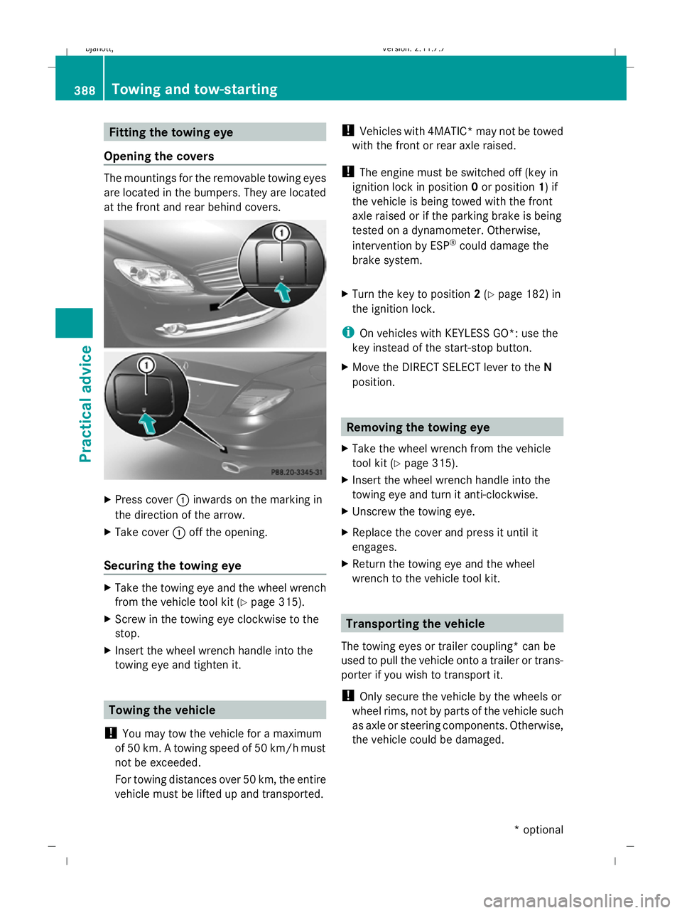
Opening the covers The mountings for the removable towing eyes
are located in the bumpers. They are located
at the front and rear behind covers. X
Press cover :inwards on the marking in
the direction of the arrow.
X Take cover :off the opening.
Securing the towing eye X
Take the towing eye and the wheel wrench
from the vehicle tool kit (Y page 315).
X Screw in the towing eye clockwise to the
stop.
X Insert the wheel wrench handle into the
towing eye and tighten it. Towing the vehicle
! You may tow the vehicle for a maximum
of 50 km. A towing speed of 50 km/h must
not be exceeded.
For towing distances over 50 km, the entire
vehicle must be lifted up and transported. !
Vehicles with 4MATIC* may not be towed
with the front or rear axle raised.
! The engine must be switched off (key in
ignition lock in position 0or position 1) if
the vehicle is being towed with the front
axle raised or if the parking brake is being
tested on a dynamometer. Otherwise,
intervention by ESP ®
could damage the
brake system.
X Turn the key to position 2(Y page 182) in
the ignition lock.
i On vehicles with KEYLESS GO*: use the
key instead of the start-stop button.
X Move the DIRECT SELECT lever to the N
position. Removing the towing eye
X Take the wheel wrench from the vehicle
tool kit (Y page 315).
X Insert the wheel wrench handle into the
towing eye and turn it anti-clockwise.
X Unscrew the towing eye.
X Replace the cover and press it until it
engages.
X Return the towing eye and the wheel
wrench to the vehicle tool kit. Transporting the vehicle
The towing eyes or trailer coupling *can be
used to pull the vehicle onto a trailer or trans-
porter if you wish to transport it.
! Only secure the vehicle by the wheels or
wheel rims, not by parts of the vehicle such
as axle or steering components. Otherwise,
the vehicle could be damaged. 388
Towing and tow-startingPractical advice
* optional
216_AKB; 2; 3, en-GB
bjanott,
Version: 2.11.7.7 2009-02-27T14:54:17+01:00 - Seite 388
Dateiname: 6515230602_buchblock.pdf; erzeugt am 04. Mar 2009 11:16:53; WK
Page 392 of 421
Fuses
Notes on changing fuses
The fuses in your vehicle serve to close down
faulty circuits. If a fuse blows, all the compo-
nents on the circuit and their functions will
fail.
Blown fuses must be replaced with fuses of
the same rating, which you can recognise by
the colour and value. The fuse ratings are lis-
ted in the fuse allocation chart. A Mercedes-
Benz Service Centre will be happy to advise
you. G
Risk of fire
Only use fuses that have been approved for
Mercedes-Benz vehicles and which have the
required fuse rating for the systems con-
cerned. Do not attempt to repair or bridge
faulty fuses. A circuit overload could other-
wise cause a fire. Have the cause traced and
rectified at a qualified specialist workshop,
e.g. a Mercedes-Benz Service Centre.
If the newly inserted fuse also blows, have the
cause traced and rectified at a qualified spe-
cialist workshop, e.g. a Mercedes-Benz
Service Centre.
! Only use fuses that have been approved
for Mercedes-Benz vehicles and which
have the correct fuse rating for the system
concerned. Otherwise, components or sys-
tems could be damaged.
! Turn off the internal on-board electrical
system of the vehicle if you are carrying out
work on the fuses. Further information can
be found in the index under "Disconnecting
the battery".
The fuses are located in various fuse boxes:
R fuse boxes on the right-hand and left-hand
sides of the dashboard
R fuse box in the engine compartment on the
left-hand side of the vehicle R
fuse box in the engine compartment on the
right-hand side of the vehicle
R fuse box in the rear
Fuse allocation chart The fuse allocation chart is located with the
vehicle tool kit in the stowage well under the
boot floor (Y
page 280). Before changing a fuse
X Park the vehicle.
X Switch off all electrical consumers.
X Remove the key from the ignition lock. Dashboard fuse boxes
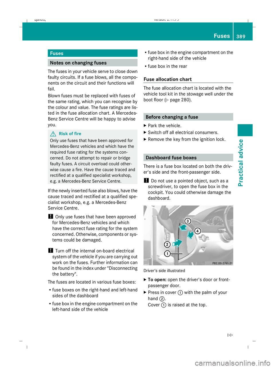
There is a fuse box located on both the driv-
er's side and the front-passenger side.
! Do not use a pointed object, such as a
screwdriver, to open the fuse box in the
cockpit. You could otherwise damage the
dashboard. Driver's side illustrated
X
To open: open the driver's door or front-
passenger door.
X Press in cover :with the palm of your
hand ;.
Cover :is raised at the top. Fuses
389Practical advice
216_AKB; 2; 3, en-GB
bjanott,V ersion: 2.11.7.7
2009-02-27T14:54:17+01:00 - Seite 389 Z
Dateiname: 6515230602_buchblock.pdf; erzeugt am 04. Mar 2009 11:16:54; WK