trailer MERCEDES-BENZ CLA-Class 2014 C117 Owner's Manual
[x] Cancel search | Manufacturer: MERCEDES-BENZ, Model Year: 2014, Model line: CLA-Class, Model: MERCEDES-BENZ CLA-Class 2014 C117Pages: 358, PDF Size: 6.6 MB
Page 12 of 358
Deactivating/activating (except
AMG vehicles) ................................ 205
Deactivating/activating (notes;
except AMG vehicles) ...................... 69
Display message ............................ 214
ETS .................................................. 68
ETS/4ETS ........................................ 68
Function/note s................................ 67
General notes .................................. 67
Important safety information ........... 68
Trailer stabilization ........................... 71
Warning lamp ................................. 247
ETS/4ETS (Electronic Traction Sys-
tem) ...................................................... 68
ETS (Electronic Traction System) ....... 68
Exhaust check ................................... 161
Exhaust pipe (cleaning instruc-
tions) .................................................. 292
Exterior lighting Setting options .............................. 108
see Lights
Exterior mirrors
Adjusting ....................................... 103
Dipping (automatic) ....................... 104
Folding in/out (automatically )....... 104
Folding in/out (electrically) ........... 103
Folding in when locking (on-board
computer) ...................................... 210
Out of position (troubleshooting) ... 104
Setting ........................................... 104
Storing settings (memory func-
tion) ............................................... 105
Storing the parking position .......... 104
Eyeglasses compartment ................. 257F
Filler cap see Fuel filler flap
Filling capacities (Technical data) ... 347
Flat tire MOExtended tire s.......................... 297
Preparing the vehicle ..................... 296
TIREFIT kit ...................................... 298
Floormats ........................................... 279
Fog lamps Extended rang e.............................. 112
Switching on/of f........................... 109 Front fog lamps
Display message ............................ 227
Switching on/of f........................... 109
Front windshield
see Windshield
Fuel
Additives ........................................ 349
Consumption statistics .................. 199
Displaying the current consump-
tion ................................................ 200
Displaying the range ...................... 200
Driving tips .................................... 161
Fuel gaug e....................................... 31
Grade (gasoline )............................ 348
Important safety notes .................. 348
Premium-grade unleaded gaso-
line ................................................. 348
Problem (malfunction) ................... 157
Refueling ........................................ 155
Tank content/reserve fue l............. 348
Fuel filler flap
Opening ......................................... 156
Fuel level
Calling up the range (on-board
computer) ...................................... 200
Fuel tank
Capacity ........................................ 348
Problem (malfunction) ................... 157
Fuses
Allocation chart ............................. 311
Before changing ............................. 310
Fuse box in the engine compart-
ment .............................................. 310
Fuse box in the front-passenger
footwell .......................................... 311
Important safety notes .................. 310 G
Garage door opener Clearing the memory ..................... 277
General notes ................................ 274
Important safety notes .................. 275
Opening/closing the garage doo r..2 77
Programming (button in the rear-
view mirror) ................................... 275
Gear indicator (on-board com-
puter) ................................................. .210 10
Index
Page 21 of 358
Top Tether
............................................ 61
Towing Important safety guidelines ........... 307
Installing the towing eye ................ 308
Removing the towing eye ............... 309
Towing a trailer
ESP ®
(Electronic Stability Pro-
gram) .............................................. .71
Towing away
With both axles on the ground ....... 309
With front axle raised ..................... 309
Tow-starting
Emergency engine starting ............ 310
Important safety notes .................. 307
Installing the towing eye ................ 308
Removing the towing eye ............... 309
Transmission
see Automatic transmission
Transmission position display ......... 147
Transporting the vehicle .................. 309
Trim pieces (cleaning instruc-
tions) .................................................. 293
Trip computer (on-board com-
puter) .................................................. 199
Trip meter see Trip odometer
Trip odometer
Calling up ....................................... 199
Resetting (on-board computer) ...... 200
Trunk
Emergency release .......................... 86
Emergency release button ............... 86
Important safety notes .................... 84
Opening/closing (manually from
outside) ............................................ 84
Opening (automatically from out-
side) ................................................. 85
Opening automatically from
inside .............................................. .85
Trunk emergency release button ....... 86
Trunk lid Display message ............................ 241
Opening dimensions ...................... 353
Trunk load (maximum) ...................... 353
Turn signals Changing bulbs (front) ................... 117
Changing bulbs (rear ).................... 117 Display message ............................ 226
Switching on/of f........................... 110
Type identification plate
see Vehicle identification plate U
Unlocking Emergency unlocking ....................... 83
From inside the vehicle (central
unlocking button) ............................. 82 V
Vanity mirror (in the sun visor) ........ 264
Vehicle Correct use ...................................... 26
Equipment ....................................... 22
Individual settings .......................... 207
Limited Warranty ............................. 27
Loading .......................................... 324
Locking (in an emergency) ............... 83
Locking (SmartKey ).......................... 76
Lowering ........................................ 340
Maintenance .................................... 23
Parking for a long period ................ 160
Pulling away ................................... 142
Raising ........................................... 337
Reporting problems ......................... 26
Securing from rolling away ............ 337
Towing away .................................. 307
Tow-starting ................................... 307
Transporting .................................. 309
Unlocking (in an emergency) ........... 83
Unlocking (SmartKey )...................... 76
Vehicle data ................................... 353
Vehicle data ....................................... 353
Vehicle dimensions ........................... 353
Vehicle emergency locking ................ 83
Vehicle identification number see VIN
Vehicle identification plate .............. 346
Vehicle maintenance see ASSYST PLUS
Vehicle tool kit .................................. 296
Video (DVD) ........................................ 203
VIN ...................................................... 346 Index
19
Page 73 of 358
If you deactivate ESP
®
:
R ESP ®
no longer improves driving stability.
R engine torque is no longer limited and the
drive wheels are able to spin.
The spinning of the wheels results in a cut-
ting action for better traction on loose sur-faces.
R traction control is still activated.
R PRE-SAFE ®
is no longer available, nor is it
activated if you brake firmly and ESP ®
intervenes.
R COLLISION PREVENTION ASSIST is no lon-
ger available; nor is it activated if you brake
firmly with assistance from ESP ®
.
R ESP ®
still provides support when you
brake.
ESP ®
trailer stabilization General information
If your vehicle/trailer combination begins to
swerve, ESP ®
assists you in this situation.
ESP ®
slows the vehicle down by braking and
limiting the engine output until the vehicle/
trailer combination has stabilized.
Important safety notes G
WARNING
If road and weather conditions are poor,
trailer stabilization will not be able to prevent the vehicle/trailer combination from swerv-
ing. Trailers with a high center of gravity can
tip over before ESP ®
can detect this. There is
a risk of an accident.
Always adapt your driving style to the prevail- ing road and weather conditions.
If your vehicle with trailer (vehicle/trailer
combination) begins to lurch, you can only
stabilize the vehicle/trailer combination by
depressing the brake firmly.
ESP ®
trailer stabilization is active above
speeds of about 40 mph (65 km/h). ESP
®
trailer stabilization does not work if
ESP ®
is deactivated or disabled because of a
malfunction. EBD (electronic brake force distribu-
tion)
General information EBD monitors and controls the brake pres-
sure on the rear wheels to improve driving
stability while braking.
Important safety notes i
Observe the "Important safety notes" sec-
tion for driving safety systems (Y page 63). G
WARNING
If EBD has malfunctioned, the rear wheels can still lock, e.g. under full braking. This increa-
ses the risk of skidding and an accident.
You should therefore adapt your driving style
to the different handling characteristics. Havethe brake system checked at a qualified spe-
cialist workshop.
Observe information regarding indicator and
warning lamps (Y page 245) as well as dis-
play messages (Y page 216). ADAPTIVE BRAKE
ADAPTIVE BRAKE enhances braking safety
and offers increased braking comfort. In addi-
tion to the braking function, ADAPTIVE BRAKE
also has the HOLD function (Y page 176) and
hill start assist (Y page 142). For further
information, see Driving tips (Y page 162). STEER CONTROL
General information STEER CONTROL helps you by transmitting a
noticeable steering force to the steering Driving safety systems
71Safety Z
Page 180 of 358
X
Fully depress the accelerator pedal.
The engine speed is increased.
The RACE START Release brake to RACE START Release brake to
start
start message appears in the multifunc-
tion display.
i If you do not release the brake pedal
within a short time, RACE START will be
canceled. The multifunction display shows
the RACE START Canceled
RACE START Canceled message.
X Take your foot off the brake, but keep the
accelerator pedal depressed.
The vehicle pulls away at maximum accel-
eration.
The RACE RACE START
START Active Active message appears
in the multifunction display.
RACE START is deactivated when the vehicle
reaches a speed of approximately 30 mph
(Canada: 50 km/h). Drive program Sis acti-
vated. SPORT handling mode remains activa-
ted.
RACE START is deactivated immediately if
you release the accelerator pedal during
RACE START or if any of the activation condi-
tions are no longer fulfilled. The RACE
RACE START START
Not Possible
Not Possible orRACE START Canceled
RACE START Canceled
message appears in the multifunction dis-
play.
i If RACE START is used repeatedly within a
short period of time, it is only available
again after the vehicle has been driven a
certain distance. 4MATIC
4MATIC ensures that all four wheels are per-
manently driven. Together with ESP ®
, it
improves the traction of your vehicle when-
ever a drive wheel spins due to insufficient
grip.
If you fail to adapt your driving style, 4MATIC can neither reduce the risk of accident nor
override the laws of physics. 4MATIC cannot
take account of road, weather and traffic con-
ditions. 4MATIC is only an aid. You are
responsible for the distance to the vehicle in front, for vehicle speed, for braking in good
time and for staying in your lane.
If a drive wheel spins due to insufficient grip:
R Only depress the accelerator pedal as far as
necessary when pulling away.
R Accelerate less when driving.
! Never tow the vehicle with one axle
raised. This may damage the transfer case.
Damage of this sort is not covered by the
Mercedes-Benz Limited Warranty. All
wheels must remain either on the ground or be fully raised. Observe the instructions for
towing the vehicle with all wheels in full
contact with the ground.
i In wintry driving conditions, the maximum
effect of 4MATIC can only be achieved if
you use winter tires (M+S tires), with snow
chains if necessary. PARKTRONIC
Important safety notes PARKTRONIC is an electronic parking aid with
ultrasonic sensors. It monitors the area
around your vehicle using six sensors in the
front bumper and six sensors in the rear
bumper. PARKTRONIC indicates visually and
audibly the distance between your vehicle
and an object.
PARKTRONIC is only an aid. It is not a replace-
ment for your attention to your immediate
surroundings. You are always responsible for
safe maneuvering, parking and exiting a park- ing space. When maneuvering, parking or
pulling out of a parking space, make sure that
there are no persons, animals or objects in
the area in which you are maneuvering.
! When parking, pay particular attention to
objects above or below the sensors, such
as flower pots or trailer drawbars. PARK-
TRONIC does not detect such objects when they are in the immediate vicinity of the
vehicle. You could damage the vehicle or
the objects. 178
Driving systemsDriving and parking
Page 184 of 358
Parking tips:
R On narrow roads, drive as close to the park-
ing space as possible.
R Parking spaces that are littered or over-
grown might be identified or measured
incorrectly.
R Parking spaces that are partially occupied
by trailer drawbars might not be identified
as such or be measured incorrectly.
R Snowfall or heavy rain may lead to a parking
space being measured inaccurately.
R Pay attention to the PARKTRONIC
(Y page 180) warning messages during the
parking procedure.
R You can intervene in the steering procedure
to correct it at any time. Active Parking
Assist will then be canceled.
R When transporting a load which protrudes
from your vehicle, you should not use
Active Parking Assist.
R Never use Active Parking Assist when snow
chains are installed.
R Make sure that the tire pressures are
always correct. This has a direct influence
on the parking characteristics of the vehi-
cle.
Use Active Parking Assist for parking spaces:
R that are parallel or at right-angles to the
direction of travel
R that are on straight roads, not bends
R that are on the same level as the road, e.g.
not on the pavement
Detecting parking spaces Objects located above the height range of
Active Parking Assist will not be detected
when the parking space is measured. These
are not taken into account when the parking
procedure is calculated, e.g. overhanging
loads, tail sections or loading ramps of goods vehicles. G
WARNING
If there are objects above the detection range, Active Parking Assist may turn prematurely.
You may cause a collision as a result. There is
a risk of an accident.
If there are objects above the detection range,
stop and deactivate Active Parking Assist.
For further information on the detection
range (Y page 179).
Active Parking Assist does not support you
with parking spaces at right-angles to the
direction of travel if:
R two parking spaces are located directly
next to one another
R the parking space is directly next to a low
obstacle such as a low curb
R you park forwards
Active Parking Assist does not support you
with parking spaces that are parallel or at
right-angles to the direction of travel if:
R the parking space is on a curb
R the parking space is apparently blocked,
for example by foliage or grass paving
blocks
R the range of movement is too small
R the parking space is bordered by an obsta-
cle which is not clearly defined such as a
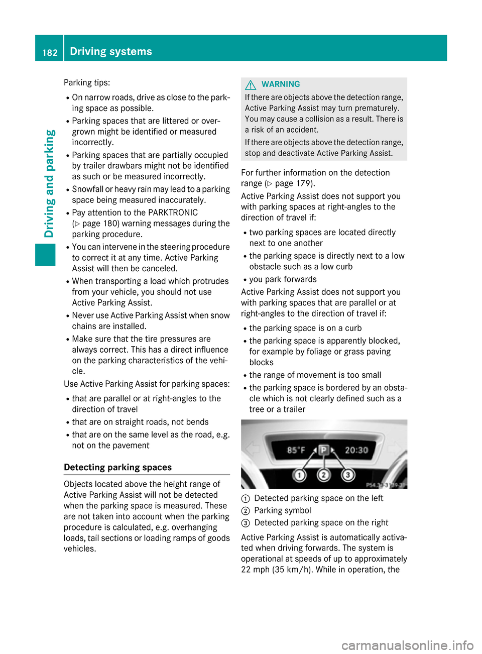
tree or a trailer 0043
Detected parking space on the left
0044 Parking symbol
0087 Detected parking space on the right
Active Parking Assist is automatically activa-
ted when driving forwards. The system is
operational at speeds of up to approximately
22 mph (35 km/h). While in operation, the 182
Driving systemsDriving and parking
Page 189 of 358
Displays in the Audio/COMAND display
The rear view camera may show a distorted
view of obstacles, show them incorrectly or
not at all. The rear view camera does not show objects in the following positions:
R very close to the rear bumper
R under the rear bumper
R in close range above the handle on the
trunk lid
! Objects not at ground level may appear to
be further away than they actually are, e.g.:
R the bumper of a parked vehicle
R the drawbar of a trailer
R the ball coupling of a trailer tow hitch
R the rear section of an HGV
R a slanted post
Use the guidelines only for orientation.
Approach objects no further than the bot-
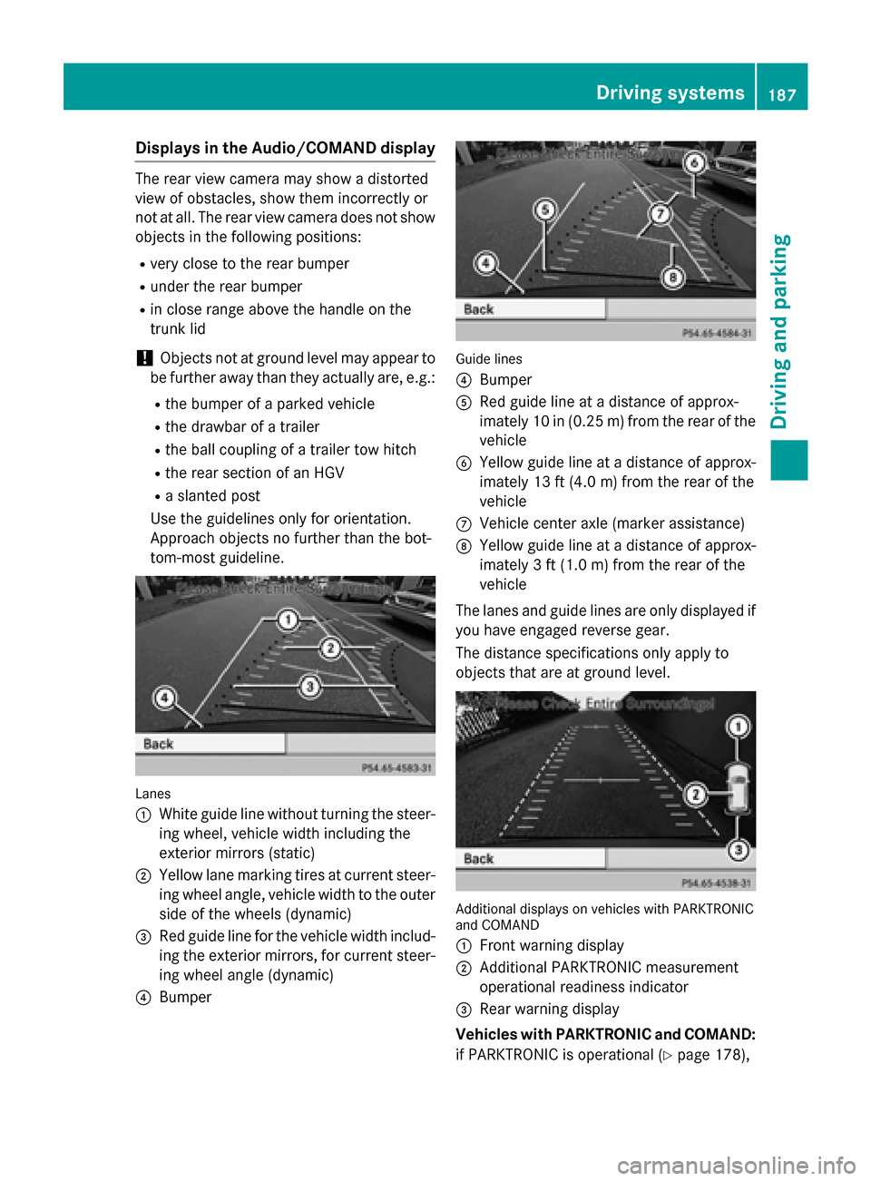
tom-most guideline. Lanes
0043
White guide line without turning the steer-
ing wheel, vehicle width including the
exterior mirrors (static)
0044 Yellow lane marking tires at current steer-
ing wheel angle, vehicle width to the outer
side of the wheels (dynamic)
0087 Red guide line for the vehicle width includ-
ing the exterior mirrors, for current steer- ing wheel angle (dynamic)
0085 Bumper Guide lines
0085
Bumper
0083 Red guide line at a distance of approx-
imately 10 in (0.25 m) from the rear of the
vehicle
0084 Yellow guide line at a distance of approx-
imately 13 ft (4.0 m) from the rear of the
vehicle
006B Vehicle center axle (marker assistance)
006C Yellow guide line at a distance of approx-
imately 3 ft (1.0 m) from the rear of the
vehicle
The lanes and guide lines are only displayed if
you have engaged reverse gear.
The distance specifications only apply to
objects that are at ground level. Additional displays on vehicles with PARKTRONIC
and COMAND
0043
Front warning display
0044 Additional PARKTRONIC measurement
operational readiness indicator
0087 Rear warning display
Vehicles with PARKTRONIC and COMAND:
if PARKTRONIC is operational (Y page 178), Driving syste
ms
187Driving an d parking Z
Page 309 of 358
Position number
0084identifies the charged battery of the other vehicle or an equivalent jump-
starting device.
X Press together cover 0043of positive clamp 0044and slide it back.
X Connect positive terminal 0044on your vehicle to positive terminal 0087of donor battery 0084
using the jumper cable, beginning with your own battery.
X Start the engine of the donor vehicle and run it at idling speed.
X Connect negative terminal 0085of donor battery 0084to ground point 0083of your vehicle using
the jumper cable, connecting the jumper cable to battery of other vehicle 0084first.
X Start the engine.
X Before disconnecting the jumper cables, let the engine run for several minutes.
X First, remove the jumper cables from ground point 0083and negative terminal 0085, then from
positive clamp 0044and positive terminal 0087. Begin each time at the contacts on your own
vehicle first.
X Close cover 0043of positive terminal 0044after removing the jumper cables.
X Have the battery checked at a qualified specialist workshop.
i Jump-starting is not considered to be a normal operating condition.
i Jumper cables and further information regarding jump-starting can be obtained at any
qualified specialist workshop. Towing and tow-starting
Important safety notes
G
WARNING
Functions relevant to safety are restricted or
no longer available if:
R the engine is not running.
R the brake system or the power steering is
malfunctioning.
R there is a malfunction in the voltage supply
or the vehicle's electrical system.
If your vehicle is being towed, much more
force may be necessary to steer or brake.
There is a risk of an accident.
In such cases, use a tow bar. Before towing,
make sure that the steering moves freely. G
WARNING
If the weight of the vehicle to be towed or tow- started is greater than the permissible gross
weight of your vehicle:
R the towing eye could detach itself
R the vehicle/trailer combination could roll-
over.
There is a risk of an accident.
When towing or tow-starting another vehicle,
its weight should not be greater than the per-
missible gross weight of your vehicle.
Information on your vehicle's gross vehicle
weight rating can be found on the vehicle
identification plate (Y page 346). Towing and tow-starting
307Breakdown assistance Z
Page 312 of 358
X
Turn the SmartKey to position 2in the igni-
tion lock.
X Shift the transmission to position N.
As soon as the vehicle has been loaded:
X Prevent the vehicle from rolling away by
applying the electric parking brake.
X Shift the transmission to position P.
X Turn the SmartKey to position 0in the igni-
tion lock and remove it.
X Secure the vehicle.
The towing eye can be used to pull the vehicle
onto a trailer or transporter for transporting
purposes. Tow-starting (emergency engine
starting)
! Vehicles with automatic transmission
must not be tow-started. You could other-
wise damage the automatic transmission.
i You can find information on "Jump-start-
ing" under (Y page 305). Fuses
Important safety notes
G
WARNING
If you manipulate or bridge a faulty fuse or if
you replace it with a fuse with a higher amper- age, the electric cables could be overloaded.
This could result in a fire. There is a risk of an
accident and injury.
Always replace faulty fuses with the specified
new fuses having the correct amperage.
! Only use fuses that have been approved
for Mercedes-Benz vehicles and which
have the correct fuse rating for the system concerned. Only use fuses marked with an
"S". Otherwise, components or systems
could be damaged.
The fuses in your vehicle serve to close down faulty circuits. If a fuse blows, all the compo- nents on the circuit and their functions stop
operating.
Blown fuses must be replaced with fuses of
the same rating, which you can recognize by
the color and value. The fuse ratings are listed
in the fuse allocation chart.
If a newly inserted fuse also blows, have the
cause traced and rectified at a qualified spe-
cialist workshop, e.g. an authorized
Mercedes-Benz Center. Before changing a fuse
X Secure the vehicle against rolling away
(Y page 157).
X Switch off all electrical consumers.
X Turn the SmartKey to position 0in the igni-
tion lock and remove it (Y page 141). All
indicator lamps in the instrument cluster
must be off.
The fuses are located in various fuse boxes:
R Fuse box in the engine compartment on the
left-hand side of the vehicle, when viewed
in the direction of travel
R Fuse box in the front-passenger footwell
The fuse allocation chart is on the fuse box in
the front-passenger footwell (Y page 311). Fuse box in the engine compartment
G
WARNING
When the hood is open and the windshield
wipers are set in motion, you can be injured by the wiper linkage. There is a risk of injury.
Always switch off the windshield wipers and
the ignition before opening the hood.
! Make sure that no moisture can enter the
fuse box when the cover is open.
! When closing the cover, make sure that it
is lying correctly on the fuse box. Moisture
seeping in or dirt could otherwise impair
the operation of the fuses. 310
FusesBreakdown assistance
Page 326 of 358
Loading the vehicle
Instruction labels for tires and loads
G
WARNING
Overloaded tires can overheat, causing a
blowout. Overloaded tires can also impair the steering and driving characteristics and lead
to brake failure. There is a risk of accident.
Observe the load rating of the tires. The load
rating must be at least half of the GAWR of
your vehicle. Never overload the tires by
exceeding the maximum load. 0043
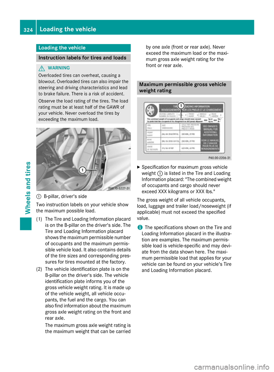
B-pillar, driver's side
Two instruction labels on your vehicle show
the maximum possible load.
(1) The Tire and Loading Information placard is on the B-pillar on the driver's side. The
Tire and Loading Information placard
shows the maximum permissible number
of occupants and the maximum permis-
sible vehicle load. It also contains details
of the tire sizes and corresponding pres-
sures for tires mounted at the factory.
(2) The vehicle identification plate is on the B-pillar on the driver's side. The vehicle
identification plate informs you of the
gross vehicle weight rating. It is made up
of the vehicle weight, all vehicle occu-
pants, the fuel and the cargo. You can
also find information about the maximum gross axle weight rating on the front and
rear axle.
The maximum gross axle weight rating is the maximum weight that can be carried by one axle (front or rear axle). Never
exceed the maximum load or the maxi-
mum gross axle weight rating for the
front or rear axle. Maximum permissible gross vehicle
weight rating
X
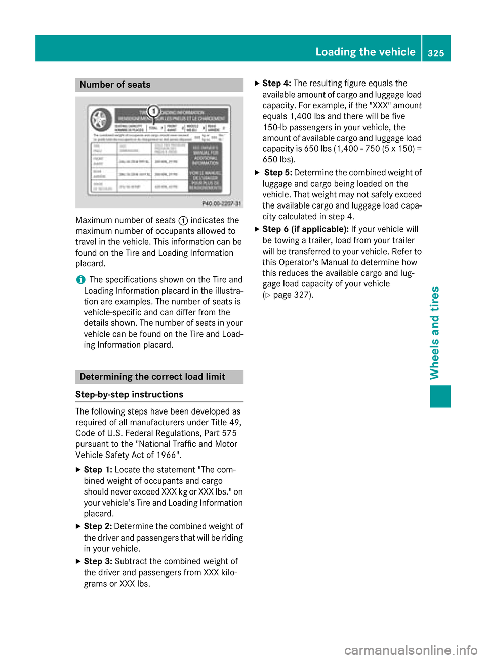
Specification for maximum gross vehicle
weight 0043is listed in the Tire and Loading
Information placard: "The combined weight of occupants and cargo should never
exceed XXX kilograms or XXX lbs."
The gross weight of all vehicle occupants,
load, luggage and trailer load/noseweight (if
applicable) must not exceed the specified
value.
i The specifications shown on the Tire and
Loading Information placard in the illustra-
tion are examples. The maximum permis-
sible load is vehicle-specific and may devi-
ate from the data shown here. The maxi-
mum permissible load that applies for your vehicle can be found on your vehicle's Tire
and Loading Information placard. 324
Loading the vehicleWheels and tires
Page 327 of 358
Number of seats
Maximum number of seats
0043indicates the
maximum number of occupants allowed to
travel in the vehicle. This information can be
found on the Tire and Loading Information
placard.
i The specifications shown on the Tire and
Loading Information placard in the illustra-
tion are examples. The number of seats is
vehicle-specific and can differ from the
details shown. The number of seats in your vehicle can be found on the Tire and Load-
ing Information placard. Determining the correct load limit
Step-by-step instructions The following steps have been developed as
required of all manufacturers under Title 49,
Code of U.S. Federal Regulations, Part 575
pursuant to the "National Traffic and Motor
Vehicle Safety Act of 1966".
X Step 1: Locate the statement "The com-
bined weight of occupants and cargo
should never exceed XXX kg or XXX lbs." on your vehicle’s Tire and Loading Information
placard.
X Step 2: Determine the combined weight of
the driver and passengers that will be riding
in your vehicle.
X Step 3: Subtract the combined weight of
the driver and passengers from XXX kilo-
grams or XXX lbs. X
Step 4: The resulting figure equals the
available amount of cargo and luggage load capacity. For example, if the "XXX" amount
equals 1,400 lbs and there will be five
150-l b passengers in your vehicle, the
amount of available cargo and luggage load
capacity is 650 lbs (1,400 00F8750 (5 x 150) =
650 lbs).
X Step 5: Determine the combined weight of
luggage and cargo being loaded on the
vehicle. That weight may not safely exceed
the available cargo and luggage load capa- city calculated in step 4.
X Step 6 (if applicable): If your vehicle will
be towing a trailer, load from your trailer
will be transferred to your vehicle. Refer to this Operator's Manual to determine how
this reduces the available cargo and lug-
gage load capacity of your vehicle
(Y page 327). Loading the vehicle
325Wheels and tires Z