reset MERCEDES-BENZ CLS 2018 Owners Manual
[x] Cancel search | Manufacturer: MERCEDES-BENZ, Model Year: 2018, Model line: CLS, Model: MERCEDES-BENZ CLS 2018Pages: 334, PDF Size: 7.87 MB
Page 7 of 334
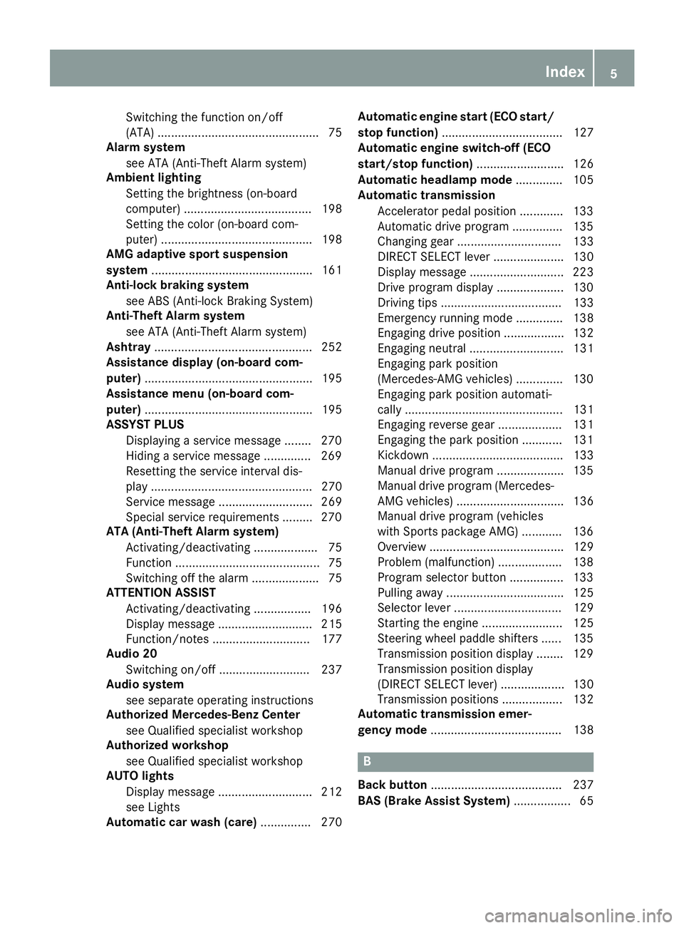
Switching the function on/off
(ATA) ................................................ 75
Alarm system
see ATA (Anti-Theft Alarm system)
Ambient lighting
Setting the brightness (on-board
computer) ...................................... 198
Setting the color (on-board com-
puter) ............................................. 198
AMG adaptive sport suspension
system ................................................ 161
Anti-lock braking system
see ABS (Anti-lock Braking System)
Anti-Theft Alarm system
see ATA (Anti-Theft Alarm system)
Ashtray ............................................... 252
Assistance display (on-board com-
puter) .................................................. 195
Assistance menu (on-board com-
puter) .................................................. 195
ASSYST PLUS
Displaying a service message ........ 270
Hiding a service message .............. 269
Resetting the service interval dis-
play ................................................ 270
Service message ............................ 269
Special service requirements ......... 270
ATA (Anti-Theft Alarm system)
Activating/deactivating ................... 75
Function ........................................... 75
Switching off the alarm .................... 75
ATTENTION ASSIST
Activating/deactivating ................. 196
Display message ............................ 215
Function/notes ............................. 177
Audio 20
Switching on/off ........................... 237
Audio system
see separate operating instructions
Authorized Mercedes-Benz Center
see Qualified specialist workshop
Authorized workshop
see Qualified specialist workshop
AUTO lights
Display message ............................ 212
see Lights
Automatic car wash (care) ............... 270 Automatic engine start (ECO start/
stop function) .................................... 127
Automatic engine switch-off (ECO
start/stop function) .......................... 126
Automatic headlamp mode .............. 105
Automatic transmission
Accelerator pedal position ............. 133
Automatic drive program ............... 135
Cha nging gear ............................... 133
DIR
ECT SELECT lever ..................... 130
Display message ............................ 223
Drive program display .................... 130
Driving tips .................................... 133
Emergency running mode .............. 138
Engaging drive position .................. 132
Engaging neutral ............................ 131
Engaging park position
(Mercedes-AMG vehicles) .............. 130
Engaging park position automati-
cally ............................................... 131
Engaging reverse gear ................... 131
Engaging the park position ............ 131
Kickdown ....................................... 133
Manual drive program .................... 135
Manual drive program (Mercedes-
AMG vehicles) ................................ 136
Manual drive program (vehicles
with Sports package AMG) ............ 136
Overview ........................................ 129
Problem (malfunction) ................... 138
Program selector button ................ 133
Pulling away ................................... 125
Selector lever ................................ 129
Starting the engine ........................ 125
Steering wheel paddle shifters ...... 135
Transmission position display ........ 129
Transmission position display
(DIRECT SELECT lever) ................... 130
Transmission positions .................. 132
Automatic transmission emer-
gency mode ....................................... 138
B
Back button ....................................... 237
BAS (Brake Assist System) ................. 65Index 5
Page 16 of 334
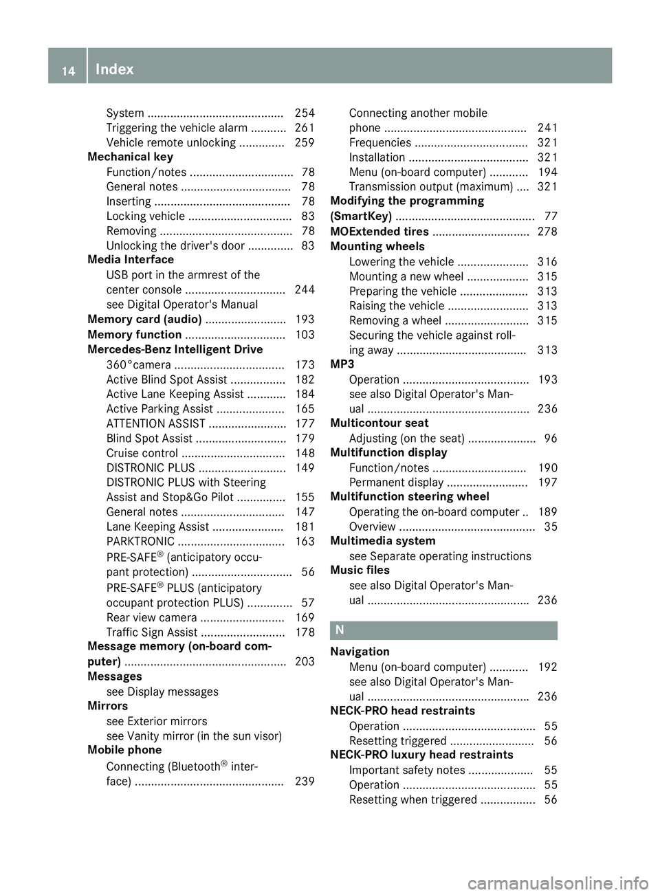
System .......................................... 254
Triggering the vehicle alarm ........... 261
Vehicle remote unlocking .............. 259
Mechanical key
Function/notes ................................ 78
General notes .................................. 78
Inserting .......................................... 78
Locking vehicle ................................ 83
Removing ......................................... 78
Unlocking the driver's door .............. 83
Media Interface
USB port in the armrest of the
center console ............................... 244
see Digital Operator's Manual
Memory card (audio) ......................... 193
Memory function ............................... 103
Mercedes-Benz Intelligent Drive
360°camera .................................. 173
Active Blind Spot Assist ................. 182
Active Lane Keeping Assist ............ 184
Active Parking Assist ..................... 165
ATTENTION ASSIST ........................ 177
Blind Spot Assist ............................ 179
Cruise control ................................ 148
DISTRONIC PLUS ........................... 149
DISTRONIC PLUS with Steering
Assist and Stop&Go Pilot ............... 155
General notes ................................ 147
Lane Keeping Assist ...................... 181
PARKTRONIC ................................. 163
PRE-SAFE ®
(anticipatory occu-
pant protection) ............................... 56
PRE-SAFE ®
PLUS (anticipatory
occupant protection PLUS) .............. 57
Rear view camera .......................... 169
Traffic Sign Assist .......................... 178
Message memory (on-board com-
puter) .................................................. 203
Messages
see Display messages
Mirrors
see Exterior mirrors
see Vanity mirror (in the sun visor)
Mobile phone
Connecting (Bluetooth ®
inter-
face) .............................................. 239 Connecting another mobile
phone ............................................ 241
Frequencies ................................... 321
Installation ..................................... 321
Menu (on-board computer) ............ 194
Transmission output (maximum) .... 321
Modifying the programming
(SmartKey) ........................................... 77
MOExtended tires .............................. 278
Mounting wheels
Lowering the vehicle ...................... 316
Mounting a new wheel ................... 315
P reparing the vehicle ..................... 313
Raising the vehicle ......................... 313
Removing a wheel .......................... 315
Securing the vehicle against roll-
ing away ........................................ 313
MP3
Operation ....................................... 193
see also Digital Operator's Man-
ual .................................................. 236
Multicontour seat
Adjusting (on the seat) ..................... 96
Multifunction display
Function/notes ............................. 190
Permanent display ......................... 197
Multifunction steering wheel
Operating the on-board compute r. .1 89
Overview .......................................... 35
Multimedia system
see Separate operating instructions
Music files
see also Digital Operator's Man-
ual ................................................. .2 36
N
Navigation
Menu (on-board computer) ............ 192
see also Digital Operator's Man-
ual ................................................. .2 36
NECK-PRO head restraints
Operation ......................................... 55
Resetting triggered .......................... 56
NECK-PRO luxury head restraints
Important safety notes .................... 55
Operation ......................................... 55
Resetting when triggered ................. 5614
Index
Page 20 of 334
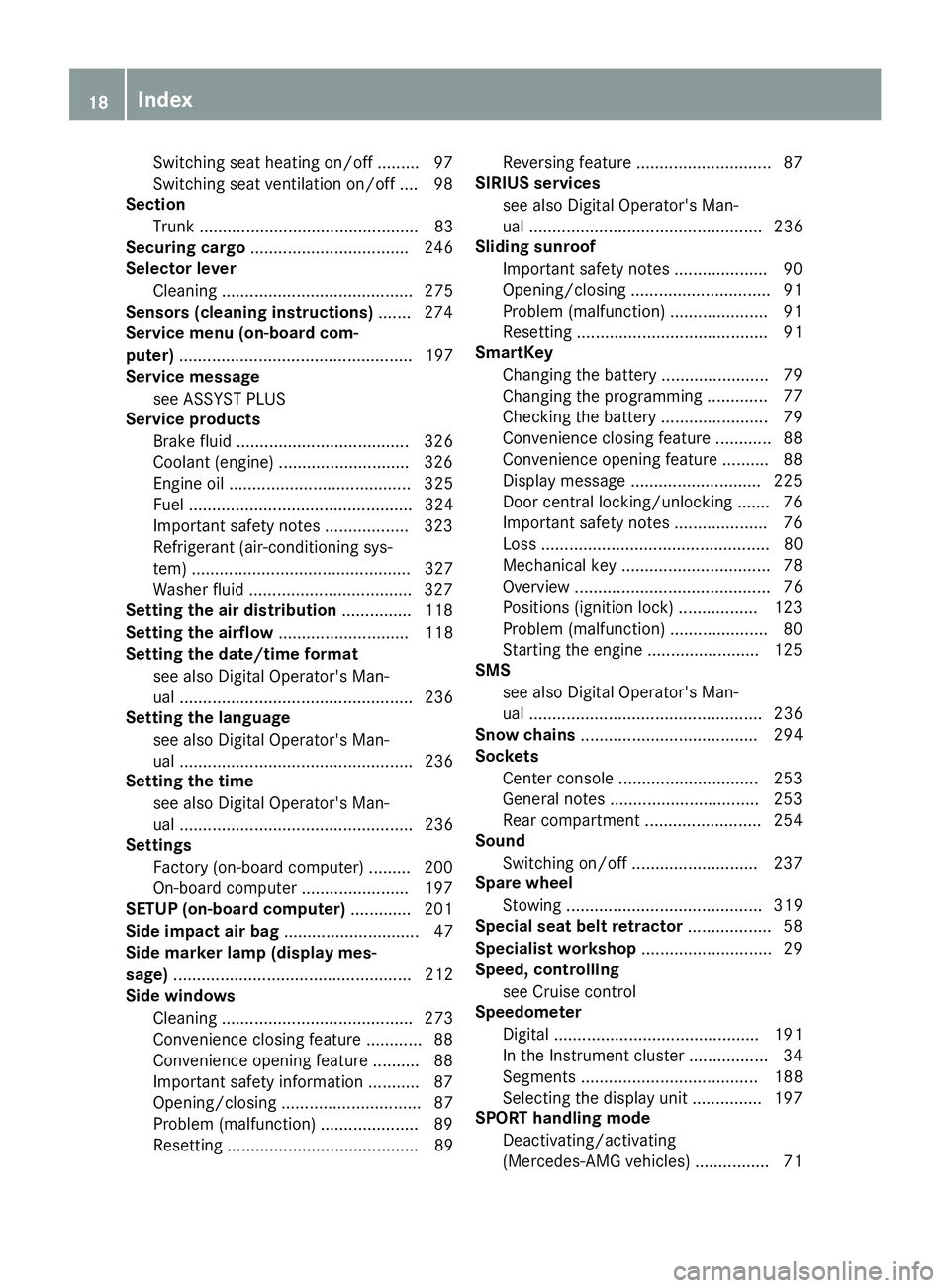
Switching seat heating on/off ......... 97
Switching seat ventilation on/off .... 98
Section
Trunk ............................................... 83
Securing cargo .................................. 246
Selector lever
Cleaning ......................................... 275
Sensors (cleaning instructions) ....... 274
Service menu (on-board com-
puter) .................................................. 197
Service message
see ASSYST PLUS
Service products
Brake fluid ..................................... 326
Coolant (engine) ............................ 326
Engine oil ....................................... 325
Fuel ................................................ 324
Important safety notes .................. 323
Refrigerant (air-conditioning sys-
tem) ............................................... 327
Washer fluid ................................... 327
Setting the air distribution ............... 118
Setting the airflow ............................ 118
Setting the date/time format
see also Digital Operator's Man-
ual .................................................. 236
Setting the language
see also Digital Operator's Man-
ual .................................................. 236
Setting the time
see also Digital Operator's Man-
ual .................................................. 236
Settings
Factory (on-board computer) ......... 200
On-board computer ....................... 197
SETUP (on-board computer) ............. 201
Side impact air bag ............................. 47
Side marker lamp (display mes-
sage) ................................................... 212
Side windows
Cleaning ......................................... 273
Convenience closing feature ............ 88
Convenience opening feature .......... 88
Important safety information ........... 87
Opening/closing .............................. 87
Problem (malfunction) ..................... 89
Resetting ......................................... 89 Reversing feature ............................. 87
SIRIUS services
see also Digital Operator's Man-
ual .................................................. 236
Sliding sunroof
Important safety notes .................... 90
Opening/closing .............................. 91
Problem (malfunction) ..................... 91
Resetting ......................................... 91
SmartKey
Changing the battery ....................... 79
Changing the programmi ng ............. 77
C h ecking the battery ....................... 79
Convenience closing feature ............ 88
Convenience opening feature .......... 88
Display message ............................ 225
Door central locking/unlocking ....... 76
Important safety notes .................... 76
Loss ................................................. 80
Mechanical key ................................ 78
Overview .......................................... 76
Positions (ignition lock) ................. 123
Problem (malfunction) ..................... 80
Starting the engine ........................ 125
SMS
see also Digital Operator's Man-
ual .................................................. 236
Snow chains ...................................... 294
Sockets
Center console .............................. 253
General notes ................................ 253
Rear compartment ......................... 254
Sound
Switching on/off ........................... 237
Spare wheel
Stowing .......................................... 319
Special seat belt retractor .................. 58
Specialist workshop ............................ 29
Speed, controlling
see Cruise control
Speedometer
Digital ............................................ 191
In the Instrument cluster ................. 34
Segments ...................................... 188
Selecting the display unit ............... 197
SPORT handling mode
Deactivating/activating
(Mercedes-AMG vehicles) ................ 7118
Index
Page 23 of 334
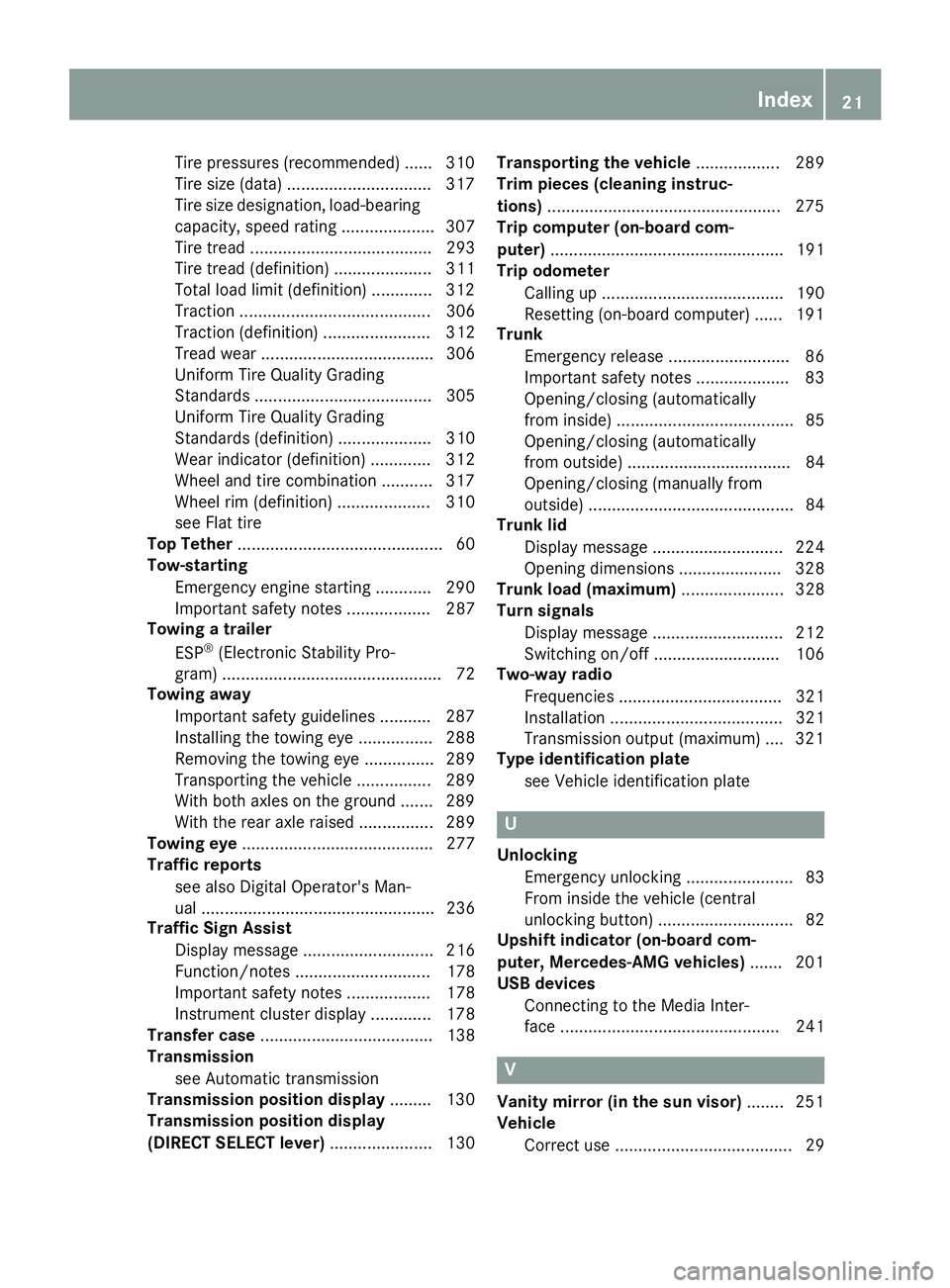
Tire pressures (recommended) ...... 310
Tire size (data) .............................. .3 17
Tire size designation, load-bearing
capacity, speed rating .................... 307
Tire tread ....................................... 293
Tire tread (definition) ..................... 311
Total load limit (definition) ............. 312
Traction ......................................... 306
Traction (definition) ....................... 312
Tread wear ..................................... 306
Uniform Tire Quality Grading
Standards ...................................... 305
Uniform Tire Quality Grading
Standards (definition) .................... 310
Wear indicator (definition) ............. 312
Wheel and tire combination ........... 317
Wheel rim (definition) .................... 310
see Flat tire
Top Tether ............................................ 60
Tow-starting
Emergency engine starting ............ 290
Important safety notes .................. 287
Towing a trailer
ESP ®
(Electronic Stability Pro-
gram) ............................................... 72
Towing away
Important safety guidelines ........... 287
Installing the towing eye ................ 288
Removing the towing eye ............... 289
Transporting the vehicle ................ 289
With both axles on the ground ....... 289
With the rear axle raised ................ 289
Towing eye ......................................... 277
Traffic reports
see also Digital Operator's Man-
ual .................................................. 236
Traffic Sign Assist
Display message ............................ 216
Function/notes ............................. 178
Important safety notes .................. 178
Instrument cluster display ............. 178
Transfer case ..................................... 138
Transmission
see Automatic transmission
Transmission position display ......... 130
Transmission position display
(DIRECT SELECT lever) ...................... 130 Transporting the vehicle .................. 289
Trim pieces (cleaning instruc-
tion s) .................................................. 275
Trip computer (on-board com-
puter) .................................................. 191
Trip odometer
Calling up ....................................... 190
Resetting (on-board computer) ...... 191
Trunk
Emergency release .......................... 86
Important safety notes .................... 83
Opening/closing (automatically
from inside) ...................................... 85
Opening/closing (automatically
from outside) ................................... 84
Opening/closing (manually from
outside) ............................................ 84
Trunk lid
Display message ............................ 224
Opening dimensions ...................... 328
Trunk load (maximum) ...................... 328
Turn signals
Display message ............................ 212
Switching on/off ........................... 106
Two-way radio
Frequencies ................................... 321
Installation ..................................... 321
Transmission output (maximum) .... 321
Type identification plate
see Vehicle identification plate
U
Unlocking
Emergency unlocking ....................... 83
From inside the vehicle (central
unlocking button) ............................. 82
Upshift indicator (on-board com-
puter, Mercedes-AMG vehicles) ....... 201
USB devices
Connecting to the Media Inter-
face ............................................... 241
V
Vanity mirror (in the sun visor) ........ 251
Vehicle
Correct use ...................................... 29 Index 21
Page 31 of 334
Diagnostics connection The diagnostic s connection is only intended fo r
th e connection of diagnostic equipmen t at a
qualified specialis t workshop .
G WARNING
If you connec t equipmen t to a diagnostic s
connection in th e vehicle, it may affec t th e
operation of vehicle systems . As a result , th e
operatin g safet y of th e vehicle could be affec -
ted. There is a ris k of an accident.
Only connec t equipmen t to a diagnostic s con-
nection in th e vehicle, whic h is approved fo r
your vehicle by Mercedes-Benz.
G WARNING
Objects in th e driver's footwell can restric t th e
peda l trave l or obstruct a depressed pedal.
The operatin g and road safet y of th e vehicle is
jeopardized. There is a ris k of an accident.
Mak e sur e that all objects in th e vehicle are
stowed correctly, and that they canno t ente r
th e driver's footwell. Install th e floormat s
securely and as specifie d in order to ensur e
sufficien t clearanc e fo r th e pedals. Do no t use
loose floormat s and do no t plac e floormat s on
to p of on e another.
! If th e engin e is switched of f and equipmen t
on th e diagnostic s connection is used , th e
starter battery may discharge.
Connectin g equipmen t to th e diagnostic s con-
nection can lead to emission s monitorin g infor-
mation bein g reset , fo r example. Thi s may lead
to th e vehicle failin g to mee t th e requirements of
th e next emission s test durin g th e main inspec-
tion .
Qualified specialist workshop An authorized Mercedes-Ben z Cente r is a quali-
fie d specialis t workshop . It has th e necessary
specialis t knowledge , tools and qualification s to
correctl y carry out th e wor k require d on your
vehicle. Thi s is especially th e cas e fo r wor k rel -
evant to safety.
Observ e th e note s in th e Maintenance Booklet . Always hav e th e followin g wor k carrie d out at an
authorized Mercedes-Ben z Center:R
wor k relevant to safet yR
servic e and maintenance wor kR
repair wor k R
alterations, installation wor k and modifica-
tion s R
wor k on electronic component s
Correct us eIf you remov e any warnin g stickers , you or oth-
ers could fail to recogniz e certain dangers.
Leave warnin g stickers in position .
Observ e th e followin g information when drivin g
your vehicle: R
th e safet y note s in this manual R
technical dat a fo r th e vehicleR
traffic rule s and regulation sR
laws and safet y standard s pertainin g to moto r
vehicles
Problem s wit h you r vehicleIf you should experience a problem wit h your
vehicle, particularly on e that you believe may
affec t it s saf e operation , we urg e you to contact
an authorized Mercedes-Ben z Cente r immedi-
ately to hav e th e problem diagnosed and recti -
fied. If th e problem is no t resolved to your sat -
isfaction , please discus s th e problem again wit h
an authorized Mercedes-Ben z Cente r or , if nec-
essary, contact us at on e of th e followin g
addresses.
In th e USA
Customer Assistanc e Cente r
Mercedes-Ben z USA, LL C
3 Mercedes Drive
Montvale, NJ 07645-0350
In Canad a
Customer Relation s Departmen t
Mercedes-Ben z Canada, Inc.
98 Vanderhoo f Avenue
Toronto , Ontario M4 G 4C9
Reporting safet y defect s
US A only:Operating safety 29
Introduction Z
Page 57 of 334
sive role in the deployment of an air bag. Nor do
they provide an indication of air bag deploy-
ment.
The vehicle can be deformed considerably, with-
out an air bag being deployed. This is the case if
only parts which are relatively easily deformed
are affected and the rate of deceleration is not
high. Conversely, air bags may be deployed even
though the vehicle suffers only minor deforma-
tion. This is the case if, for example, very rigid
vehicle parts such as longitudinal body mem-
bers are hit, and sufficient deceleration occurs
as a result.
If the restraint system control unit detects a side
impact or if the vehicle rolls over, the applicable
components of the restraint system are activa-
ted independently of each other depending on
the apparent type of accident. R
Side impact air bags and pelvis air bag on the
side the impact takes place, independently of
the Emergency Tensioning Device and the use
of the seat belt on the driver's seat and outer
seats in the second row -
the OCS system detects that the front-
passenger seat is occupied or -
the belt tongue is engaged in the belt
buckle of the front-passenger seat R
Window curtain air bag on the side of impact,
independently of the use of the seat belt and
independently of whether the front-
passenger seat is occupied R
Emergency Tensioning Devices, if the system
determines that deployment can offer addi-
tional protection in this situation R
Window curtain air bags on the driver's and
front-passenger side in certain situations
when the vehicle rolls over, if the system
determines that deployment can offer addi-
tional protection to that provided by the seat
belt
i Not all air bags are deployed in an accident.
The different air bag systems work independ-
ently of each other.
How the air bag system works is determined
by the severity of the accident detected,
especially the vehicle deceleration or accel-
eration and the apparent type of accident: R
Frontal collision R
Side impact R
Rollover NECK-PRO head restraints/NECK-
PRO luxury head restraints
Important safety notes
G WARNING
The function of the head restraint may be
impaired if you: R
attach objects such as coat hangers to the
head restraints, for example R
use head restraint covers
If you do so, the head restraints cannot fulfill
their intended protective function in the event
of an accident. In addition, objects attached
to the head restraints could endanger other
vehicle occupants. There is an increased risk
of injury.
Do not attach any objects to the head
restraints and do not use head restraint cov-
ers.
Method of operation NECK-PRO head restraints/NECK-PRO luxury
head restraints offer additional protection
against head and neck injuries. In the event of a
rear collision of a certain severity, the NECK-
PRO head restraints/NECK-PRO luxury head
restraints on the driver's and front-passenger
seats are moved forwards and upwards. This
provides better head support.
If the NECK-PRO head restraints/NECK-PRO
luxury head restraints have been triggered in an
accident, reset the NECK-PRO head restraints/
NECK-PRO luxury head restraints on the driver's
seat and the front-passenger seat
( Y
page 56). Otherwise, the additional protec-
tion will not be available in the event of another
rear-end collision. You can see that a NECK-PRO
head restraint/NECK-PRO luxury head restraint
has been triggered if it is tilted forward and can
no longer be adjusted.
Mercedes-Benz recommends that you have the
functionality of the NECK-PRO head restraints/
NECK-PRO luxury head restraints checked at a
qualified specialist workshop after a rear-end
collision.Occupant safety 55
Safety Z
Page 58 of 334
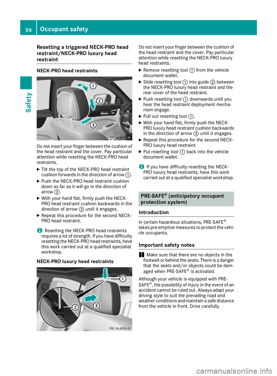
Resetting a triggered NECK-PRO head
restraint/NECK-PRO luxury head
restraint NECK-PRO head restraints
Do not insert your finger between the cushion of
the head restraint and the cover. Pay particular
attention while resetting the NECK-PRO head
restraints. X
Tilt the top of the NECK-PRO head restraint
cushion forwards in the direction of arrow �C .X
Push the NECK-PRO head restraint cushion
down as far as it will go in the direction of
arrow �D .X
With your hand flat, firmly push the NECK-
PRO head restraint cushion backwards in the
direction of arrow �
Page 89 of 334
Side windows
Important safety notes
G WARNING
While opening the side windows, body parts
could become trapped between the side win-
dow and the door frame as the side window
moves. There is a risk of injury.
Make sure that nobody touches the side win-
dow during the opening procedure. If some-
body becomes trapped, release the switch or
pull the switch to close the side window again.
G WARNING
While closing the side windows, body parts in
the closing area could become trapped. There
is a risk of injury.
When closing make sure that no parts of the
body are in the closing area. If somebody
becomes trapped, release the switch or press
the switch to open the side window again.
G WARNING
If children operate the side windows they
could become trapped, particularly if they are
left unsupervised. There is a risk of injury.
Activate the override feature for the rear side
windows. When leaving the vehicle, always
take the SmartKey with you and lock the vehi-
cle. Never leave children unsupervised in the
vehicle.
Side window reversing feature The side windows are equipped with an auto-
matic reversing feature. If a solid object blocks
or restricts a side window during the closing
process, the side window opens again automat-
ically. However, the automatic reversing feature
is only an aid and is not a substitute for your
attentiveness when closing a side window. G WARNING
The reversing feature does not react: R
to soft, light and thin objects, e.g. small fin-
gers R
over the last 1/6 in(4 mm) of the closing
movement R
during resetting R
when closing the side window again man-
ually immediately after automatic reversing
This means that the reversing feature cannot
prevent someone being trapped in these sit-
uations. There is a risk of injury.
Make sure that no body parts are in close
proximity during the closing procedure. If
someone becomes trapped, press the switch
to open the side window again.
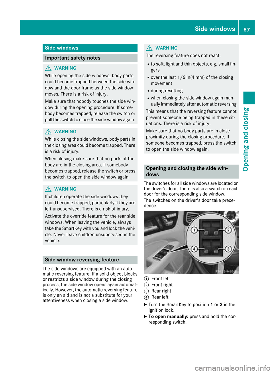
Opening and closing the side win-
dows The switches for all side windows are located on
the driver's door. There is also a switch on each
door for the corresponding side window.
The switches on the driver's door take prece-
dence.
�C
Front left
�D
Front right
�
Page 91 of 334
X
Make sure that all the side windows and the
sliding sunroof are closed. X
Make sure that all the side windows are
closed. X
To interrupt convenience closing: release
the �7 button.
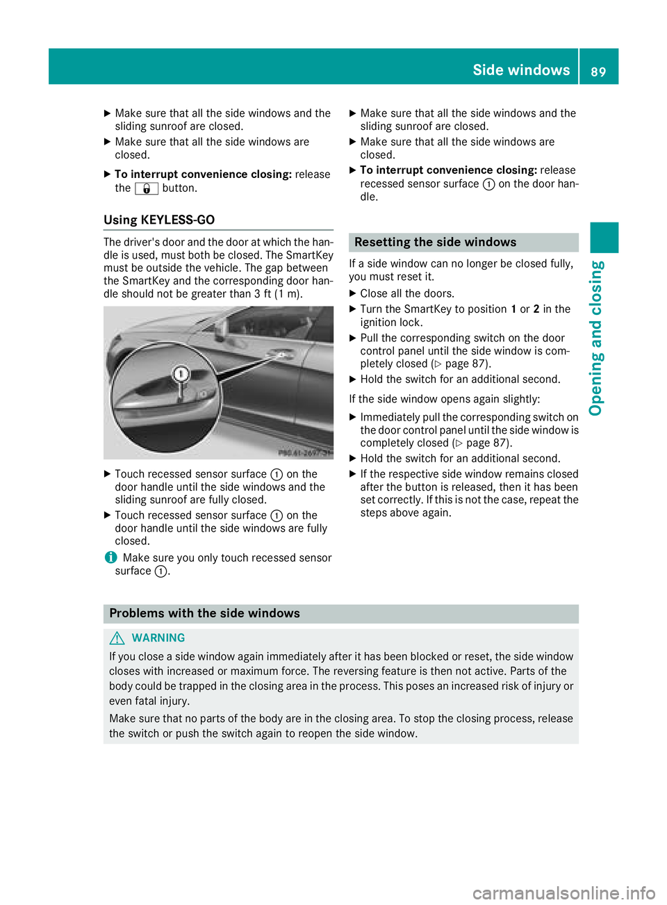
Using KEYLESS-GO The driver's door and the door at which the han-
dle is used, must both be closed. The SmartKey
must be outside the vehicle. The gap between
the SmartKey and the corresponding door han-
dle should not be greater than 3 ft (1 m).
X
Touch recessed sensor surface �C on the
door handle until the side windows and the
sliding sunroof are fully closed. X
Touch recessed sensor surface �C on the
door handle until the side windows are fully
closed.
i Make sure you only touch recessed sensor
surface �C . X
Make sure that all the side windows and the
sliding sunroof are closed. X
Make sure that all the side windows are
closed. X
To interrupt convenience closing: release
recessed sensor surface �C on the door han-
dle.
Resetting the side windows If a side window can no longer be closed fully,
you must reset it. X
Close all the doors. X
Turn the SmartKey to position 1 or 2 in the
ignition lock. X
Pull the corresponding switch on the door
control panel until the side window is com-
pletely closed ( Y
page 87). X
Hold the switch for an additional second.
If the side window opens again slightly: X
Immediately pull the corresponding switch on
the door control panel until the side window is
completely closed ( Y
page 87).X
Hold the switch for an additional second. X
If the respective side window remains closed
after the button is released, then it has been
set correctly. If this is not the case, repeat the
steps above again.
Problems with the side windows
G WARNING
If you close a side window again immediately after it has been blocked or reset, the side window
closes with increased or maximum force. The reversing feature is then not active. Parts of the
body could be trapped in the closing area in the process. This poses an increased risk of injury or
even fatal injury.
Make sure that no parts of the body are in the closing area. To stop the closing process, release
the switch or push the switch again to reopen the side window. Side windows 89
Opening and closing Z
Page 93 of 334
G WARNING
The reversing feature does not react: R
to soft, light and thin objects, e.g. small fin-
gers R
over the last 1/6 in (4 mm) of the closing
movement R
during resetting R
when closing the sliding sunroof again man-
ually immediately after automatic reversing
This means that the reversing feature cannot
prevent someone being trapped in these sit-
uations. There is a risk of injury.
Make sure that no body parts are in close
proximity during the closing procedure.
If somebody becomes trapped: R
release the switch immediately, or R
press the switch in any direction during the
automatic closing process
The closing process is stopped.
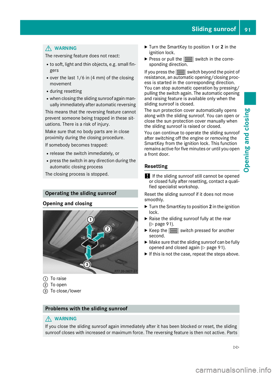
Operating the sliding sunroof
Opening and closing
�C
To raise
�D
To open
�