trunk release MERCEDES-BENZ CLS-Class 2015 W218 User Guide
[x] Cancel search | Manufacturer: MERCEDES-BENZ, Model Year: 2015, Model line: CLS-Class, Model: MERCEDES-BENZ CLS-Class 2015 W218Pages: 398, PDF Size: 7.43 MB
Page 171 of 398
Closing the fuel filler flap
X
Replace the cap on the filler neck and turn
clockwise until it engages audibly.
X Close the fuel filler flap.
Close the fuel filler flap before locking the
vehicle. Otherwise, the locking pin of the cen-
tral locking prevents the fuel filler flap from
closing.
If you are driving with the fuel filler cap open, the 8 reserve fuel warning lamp flashes. A
message appears in the multifunction display
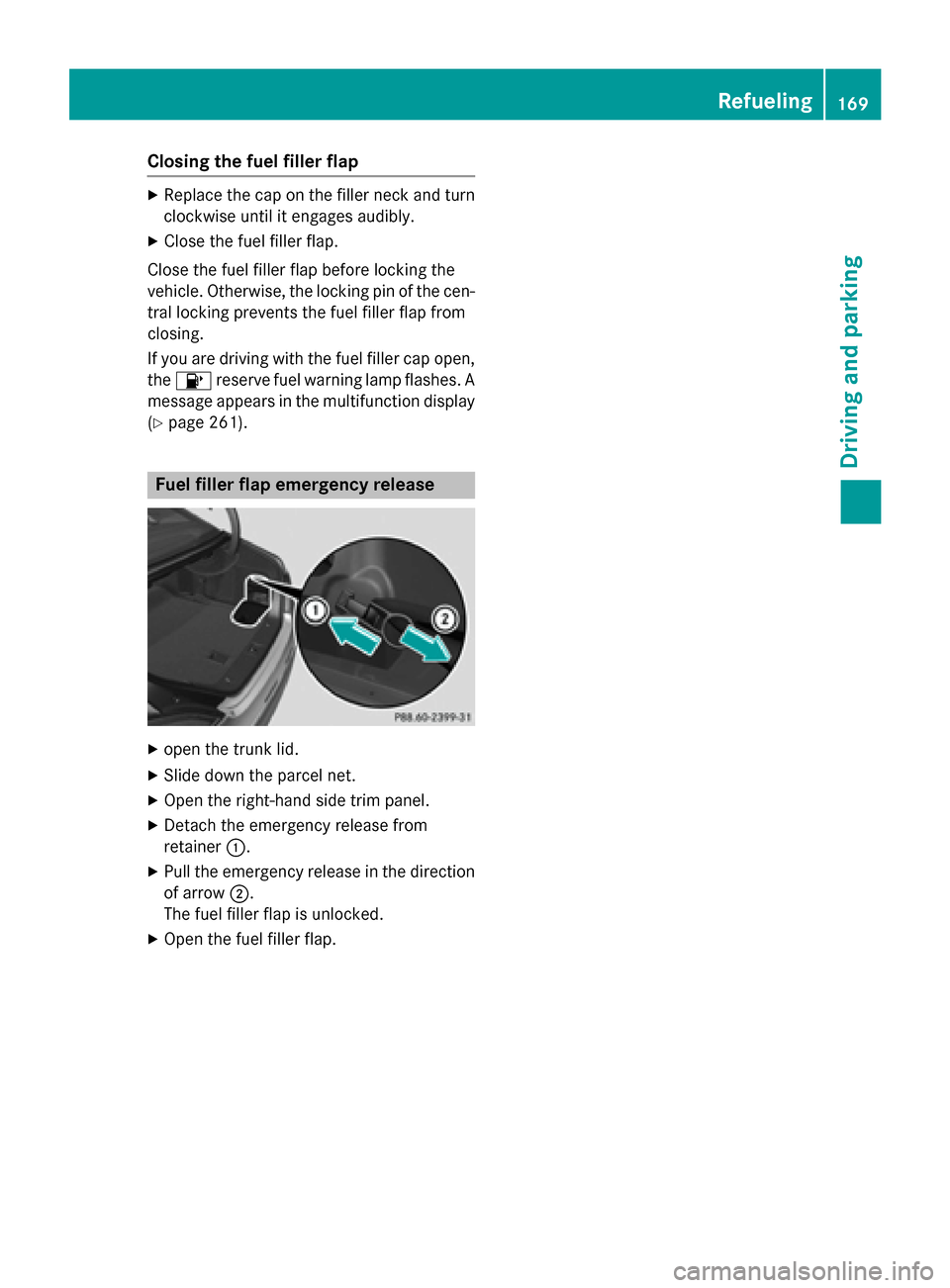
(Y page 261). Fuel filler flap emergency release
X
open the trunk lid.
X Slide down the parcel net.
X Open the right-hand side trim panel.
X Detach the emergency release from
retainer :.
X Pull the emergency release in the direction
of arrow ;.
The fuel filler flap is unlocked.
X Open the fuel filler flap. Refueling
169Driving and parking Z
Page 172 of 398
Problems with fuel and the fuel tank
Problem
Possible causes/consequences and
M
MSolutions Fuel is leaking from the
vehicle. G
WARNING
The fuel line or the fuel tank is faulty.
Risk of explosion or fire.
X Apply the electric parking brake.
X Switch off the engine.
X Remove the SmartKey from the ignition lock.
or, on vehicles with KEYLESS‑GO: X Open the driver's door.
The on-board electronics now have status 0. This is the same as
the SmartKey having been removed.
X Do not restart the engine under any circumstances.
X Consult a qualified specialist workshop. The fuel filler flap can-
not be opened. The fuel filler flap is not unlocked.
X Unlock the vehicle (Y page 84). The SmartKey battery is discharged or nearly discharged.
X Unlock the vehicle using the mechanical key (Y page 86).
X Open the trunk lid.
X
X Manually unlock the fuel filler flap using the emergency release
(Y page 169). The fuel filler flap is unlocked, but the opening mechanism is jam-
med.
X Consult a qualified specialist workshop. Parking
Important safety notes
G
WARNING
Flammable material such as leaves, grass or
twigs may ignite if they come into contact with hot parts of the exhaust system or exhaust
gas flow. There is a risk of fire.
Park the vehicle so that no flammable mate-
rials come into contact with parts of the vehi- cle which are hot. Take particular care not to park on dry grassland or harvested grain
fields. G
WARNING
If you switch off the ignition while driving,
safety-relevant functions are only available
with limitations, or not at all. This could affect, for example, the power steering and the brake
boosting effect. You will require considerably
more effort to steer and brake. There is a risk of an accident.
Do not switch off the ignition while driving. 170
ParkingDriving and parking
Page 292 of 398
Observe the loading guidelines (Y
page 286).
The left-hand and right-hand rear seat backr- ests can be folded down separately to
increase the trunk capacity.
Folding the seat backrest forward i
Vehicles with memory function: when you
fold one or both parts of the rear seat back- rest forwards, the respective front seat
moves forward slightly, when necessary, inorder to avoid contact.
X Vehicles without memory function: if nec-
essary, move the driver's or front-
passenger seat forward.
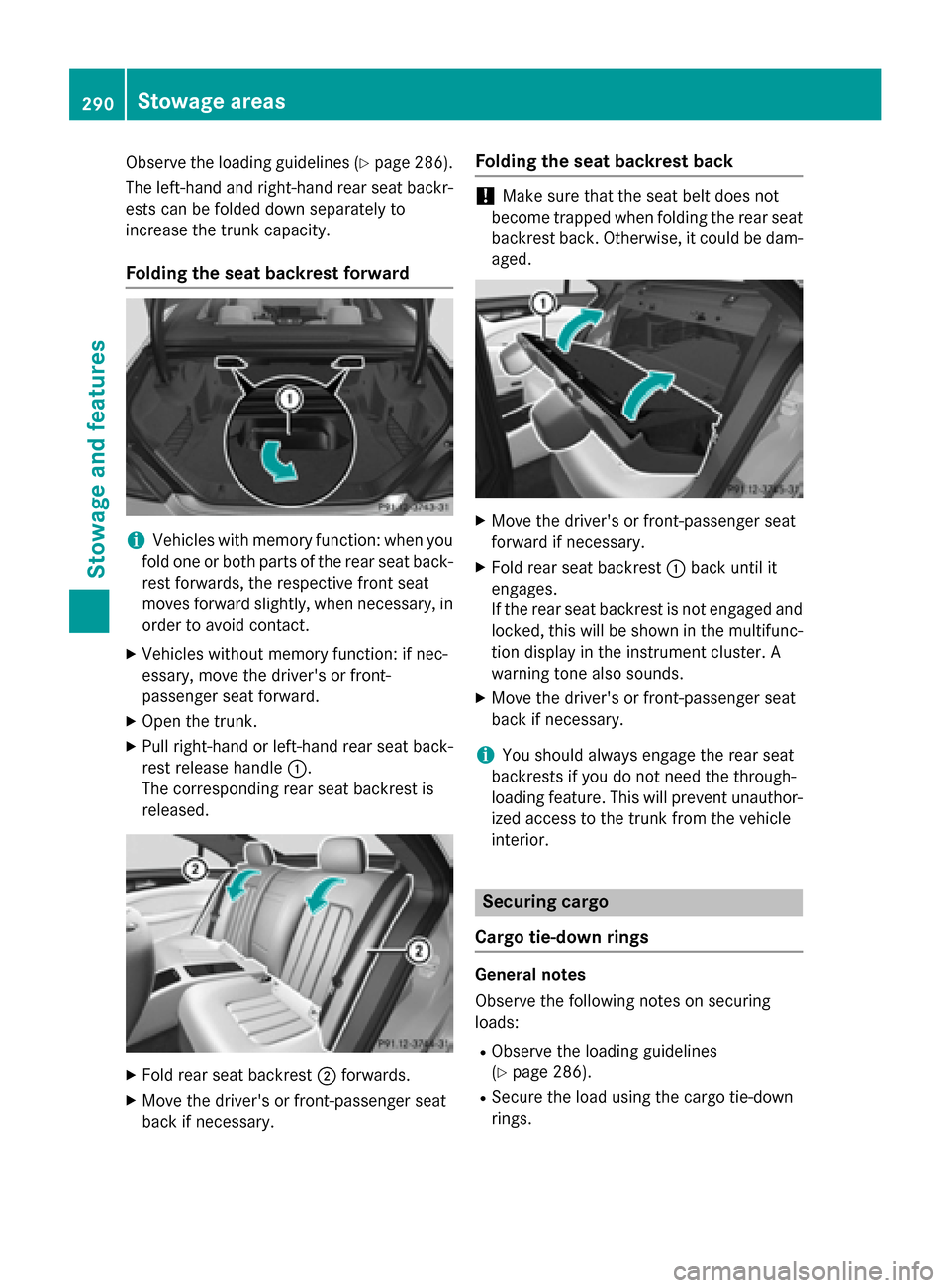
X Open the trunk.
X Pull right-hand or left-hand rear seat back-
rest release handle :.
The corresponding rear seat backrest is
released. X
Fold rear seat backrest ;forwards.
X Move the driver's or front-passenger seat
back if necessary. Folding the seat backrest back !
Make sure that the seat belt does not
become trapped when folding the rear seat backrest back. Otherwise, it could be dam- aged. X
Move the driver's or front-passenger seat
forward if necessary.
X Fold rear seat backrest :back until it
engages.
If the rear seat backrest is not engaged and
locked, this will be shown in the multifunc-
tion display in the instrument cluster. A
warning tone also sounds.
X Move the driver's or front-passenger seat
back if necessary.
i You should always engage the rear seat
backrests if you do not need the through-
loading feature. This will prevent unauthor-
ized access to the trunk from the vehicle
interior. Securing cargo
Cargo tie-down rings General notes
Observe the following notes on securing
loads:
R Observe the loading guidelines
(Y page 286).
R Secure the load using the cargo tie-down
rings. 290
Stowage areasStowage and features
Page 343 of 398
The fuses are located in various fuse boxes:
R Fuse box in the engine compartment on the
left-hand side of the vehicle, when viewed
in the direction of travel
R fuse box located in the trunk on the right-
hand side when viewed in the direction of
travel
the fuse allocation chart is located in the vehi-
cle tool kit in the stowage compartment
under the trunk floor (Y page 326).Fuse box in the engine compartment
Pay attention to the important safety notes
(Y page 340). G
WARNING
When the hood is open and the windshield
wipers are set in motion, you can be injured by the wiper linkage. There is a risk of injury.
Always switch off the windshield wipers and
the ignition before opening the hood.
! Make sure that no moisture can enter the
fuse box when the cover is open.
! When closing the cover, make sure that it
is lying correctly on the fuse box. Moisture
seeping in or dirt could otherwise impair
the operation of the fuses. X
Make sure that the windshield wipers are
turned off.
X Open the hood.
X Use a dry cloth to remove any moisture
from the fuse box. X
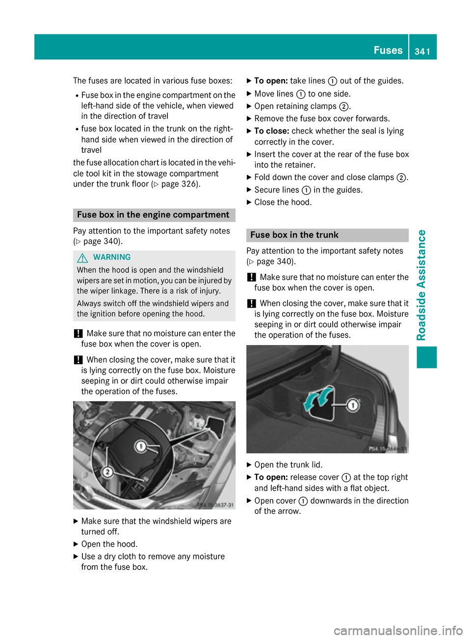
To open: take lines :out of the guides.
X Move lines :to one side.
X Open retaining clamps ;.
X Remove the fuse box cover forwards.
X To close: check whether the seal is lying
correctly in the cover.
X Insert the cover at the rear of the fuse box
into the retainer.
X Fold down the cover and close clamps ;.
X Secure lines :in the guides.
X Close the hood. Fuse box in the trunk
Pay attention to the important safety notes
(Y page 340).
! Make sure that no moisture can enter the
fuse box when the cover is open.
! When closing the cover, make sure that it
is lying correctly on the fuse box. Moisture seeping in or dirt could otherwise impair
the operation of the fuses. X
Open the trunk lid.
X To open: release cover :at the top right
and left-hand sides with a flat object.
X Open cover :downwards in the direction
of the arrow. Fuses
341Roadside Assistance Z
Page 382 of 398
tem/the tire pressure monitor when the
damaged wheel has been replaced with a
new wheel.
Vehicles with tire pressure monitor: after
mounting an emergency spare wheel, the
system may still display the tire pressure of the removed wheel for a few minutes. The
value displayed for the mounted emer-
gency spare wheel is not the same as the
current tire pressure of the emergency
spare wheel. "Minispare" emergency spare wheel/
collapsible spare wheel
Removing the "Minispare" emergency
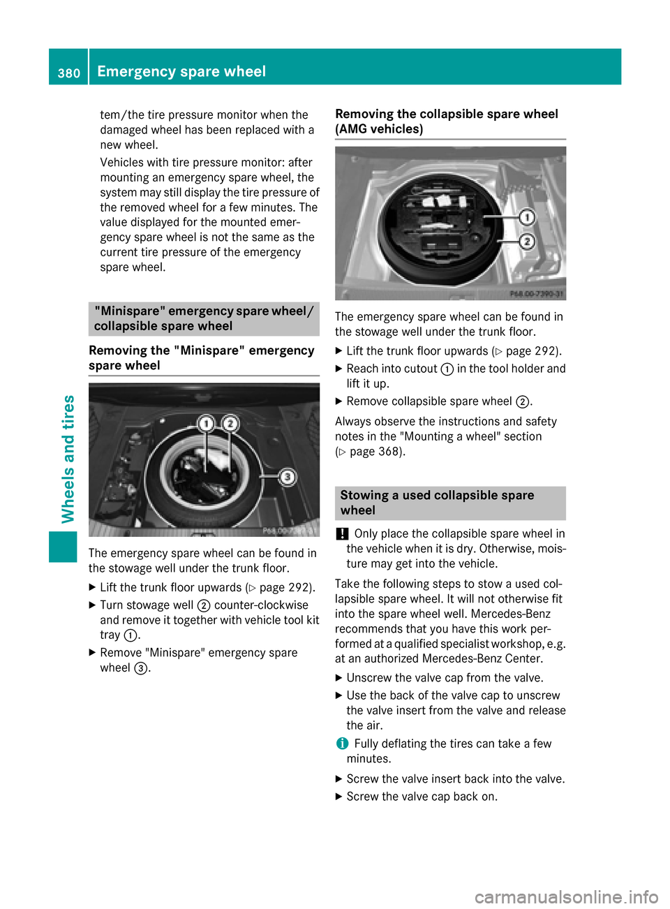
spare wheel The emergency spare wheel can be found in
the stowage well under the trunk floor.
X Lift the trunk floor upwards (Y page 292).
X Turn stowage well ;counter-clockwise
and remove it together with vehicle tool kit
tray :.
X Remove "Minispare" emergency spare
wheel =. Removing the collapsible spare wheel
(AMG vehicles) The emergency spare wheel can be found in
the stowage well under the trunk floor.
X Lift the trunk floor upwards (Y page 292).
X Reach into cutout :in the tool holder and
lift it up.
X Remove collapsible spare wheel ;.
Always observe the instructions and safety
notes in the "Mounting a wheel" section
(Y page 368). Stowing a used collapsible spare
wheel
! Only place the collapsible spare wheel in
the vehicle when it is dry. Otherwise, mois-
ture may get into the vehicle.
Take the following steps to stow a used col-
lapsible spare wheel. It will not otherwise fit
into the spare wheel well. Mercedes-Benz
recommends that you have this work per-
formed at a qualified specialist workshop, e.g. at an authorized Mercedes-Benz Center.
X Unscrew the valve cap from the valve.
X Use the back of the valve cap to unscrew
the valve insert from the valve and release
the air.
i Fully deflating the tires can take a few
minutes.
X Screw the valve insert back into the valve.
X Screw the valve cap back on. 380
Emergency spare
wheelWheels and tires
Page 383 of 398
X
Remove the protective sheet from the vehi-
cle tool kit and pull it over the collapsible
spare wheel.
X Stow the collapsible spare wheel in the
emergency spare wheel well under the
trunk. Inflating the collapsible spare wheel
! Inflate the collapsible spare wheel using
the tire inflation compressor before lower-
ing the vehicle. The wheel rim could other-
wise be damaged.
! Do not operate the tire inflation compres-
sor for longer than eight minutes at a time
without a break. It may otherwise overheat.
The tire inflation compressor can be oper-
ated again once it has cooled down. X
Mount the collapsible spare wheel as
described (Y page 368).
The collapsible spare wheel must be moun-
ted before it is inflated.
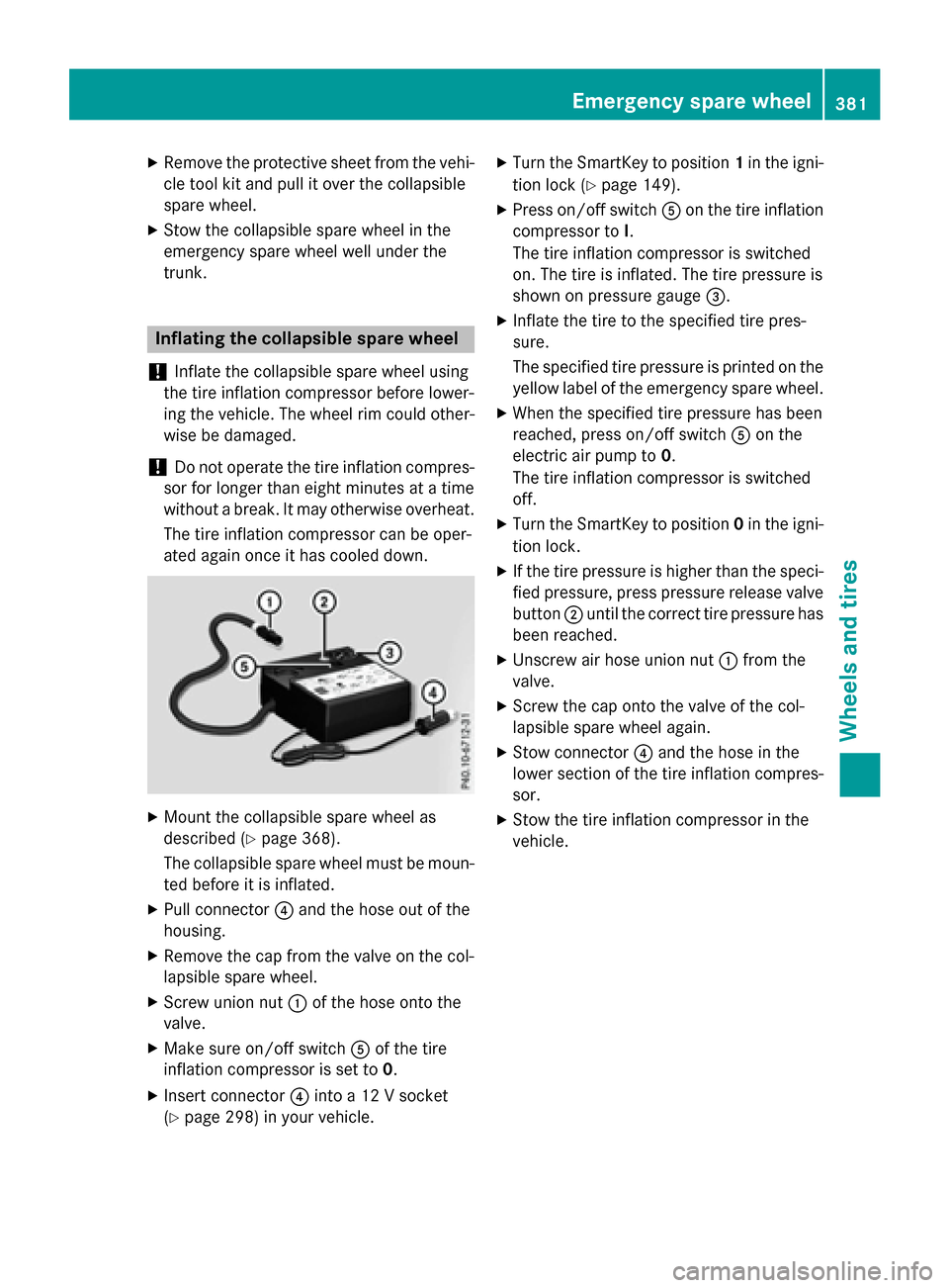
X Pull connector ?and the hose out of the
housing.
X Remove the cap from the valve on the col-
lapsible spare wheel.
X Screw union nut :of the hose onto the
valve.
X Make sure on/off switch Aof the tire
inflation compressor is set to 0.
X Insert connector ?into a 12 V socket
(Y page 298) in your vehicle. X
Turn the SmartKey to position 1in the igni-
tion lock (Y page 149).
X Press on/off switch Aon the tire inflation
compressor to I.
The tire inflation compressor is switched
on. The tire is inflated. The tire pressure is
shown on pressure gauge =.
X Inflate the tire to the specified tire pres-
sure.
The specified tire pressure is printed on the
yellow label of the emergency spare wheel.
X When the specified tire pressure has been
reached, press on/off switch Aon the
electric air pump to 0.
The tire inflation compressor is switched
off.
X Turn the SmartKey to position 0in the igni-
tion lock.
X If the tire pressure is higher than the speci-
fied pressure, press pressure release valve
button ;until the correct tire pressure has
been reached.
X Unscrew air hose union nut :from the
valve.
X Screw the cap onto the valve of the col-
lapsible spare wheel again.
X Stow connector ?and the hose in the
lower section of the tire inflation compres-
sor.
X Stow the tire inflation compressor in the
vehicle. Emergency spare wheel
381Wheels andtires Z