MERCEDES-BENZ CLS COUPE 2008 Owners Manual
Manufacturer: MERCEDES-BENZ, Model Year: 2008, Model line: CLS COUPE, Model: MERCEDES-BENZ CLS COUPE 2008Pages: 329, PDF Size: 29.26 MB
Page 181 of 329
Loading and stowing
178
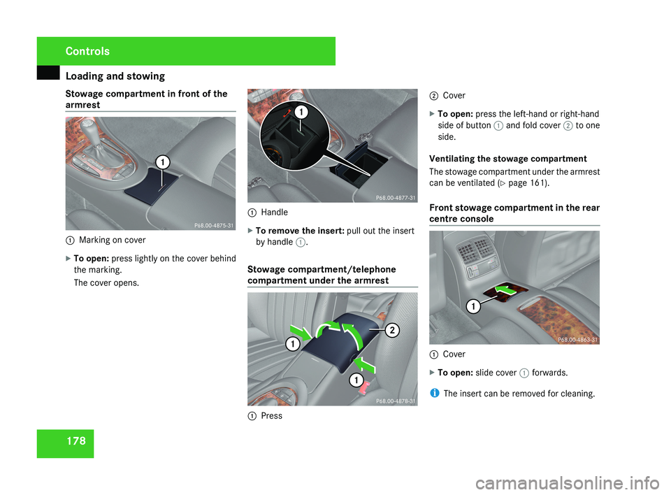
Stowage compartment in front of the
armrest
1
Marking on cover
X To open: press lightly on the cover behind
the marking.
The cover opens. 1
Handle
X To remove the insert: pull out the insert
by handle 1.
Stowage compartment/telephone
compartment under the armrest 1
Press 2
Cover
X To open: press the left-hand or right-hand
side of button 1 and fold cover 2 to one
side.
Ventilating the stowage compartment
The stowage compartment under the armrest
can be ventilated (Y page 161).
Front stowage compartment in the rear
centre console 1
Cover
X To open: slide cover 1 forwards.
i The insert can be removed for cleaning. Controls
219_AKB; 2; 4, en-GB
mkalafa,
2007-11-13T09:28:36+01:00 - Seite 178
Page 182 of 329
Loading and stowing
179
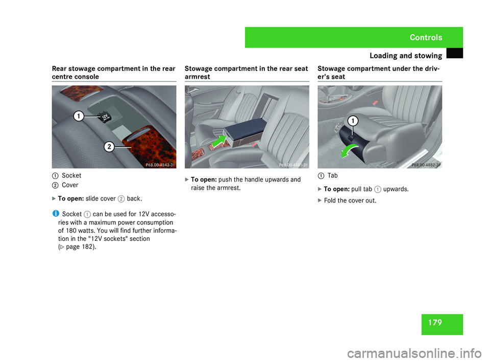
Rear stowage compartment in the rear
centre console
1
Socket
2 Cover
X To open: slide cover 2 back.
i Socket 1 can be used for 12V accesso-
ries with a maximum power consumption
of 180 watts. You will find further informa-
tion in the "12V sockets" section
(Y page 182). Stowage compartment in the rear seat
armrest X
To open: push the handle upwards and
raise the armrest. Stowage compartment under the driv-
er's seat 1
Tab
X To open: pull tab 1 upwards.
X Fold the cover out. Controls
219_AKB; 2; 4, en-GB
mkalafa,
2007-11-13T09:28:36+01:00 - Seite 179
Page 183 of 329
Features
180 Features
Sun visors
G
Risk of accident
Keep the mirrors in the sun visors covered
while driving. You could otherwise be daz-
zled by bright lights, impairing your view of
traffic conditions. As a result you could
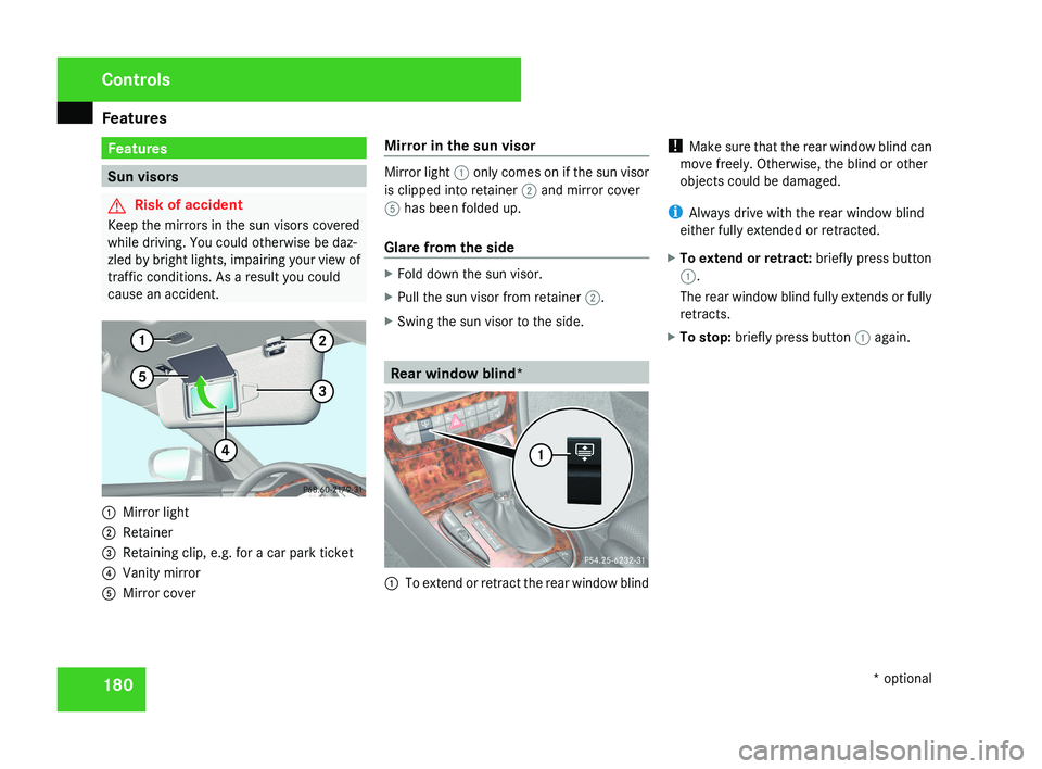
cause an accident.1 Mirror light
2 Retainer
3 Retaining clip, e.g. for a car park ticket
4 Vanity mirror
5 Mirror cover Mirror in the sun visor
Mirror light
1 only comes on if the sun visor
is clipped into retainer 2 and mirror cover
5 has been folded up.
Glare from the side
X Fold down the sun visor.
X Pull the sun visor from retainer 2.
X Swing the sun visor to the side.
Rear window blind*
1 To extend or retract the rear window blind !
Make sure that the rear window blind can
move freely. Otherwise, the blind or other
objects could be damaged.
i Always drive with the rear window blind
either fully extended or retracted.
X To extend or retract: briefly press button
1.
The rear window blind fully extends or fully
retracts.
X To stop: briefly press button 1 again.
Controls
* optional
219_AKB; 2; 4, en-GB
mkalafa,
2007-11-13T09:28:36+01:00 - Seite 180
Page 184 of 329
Features
181Ashtray*
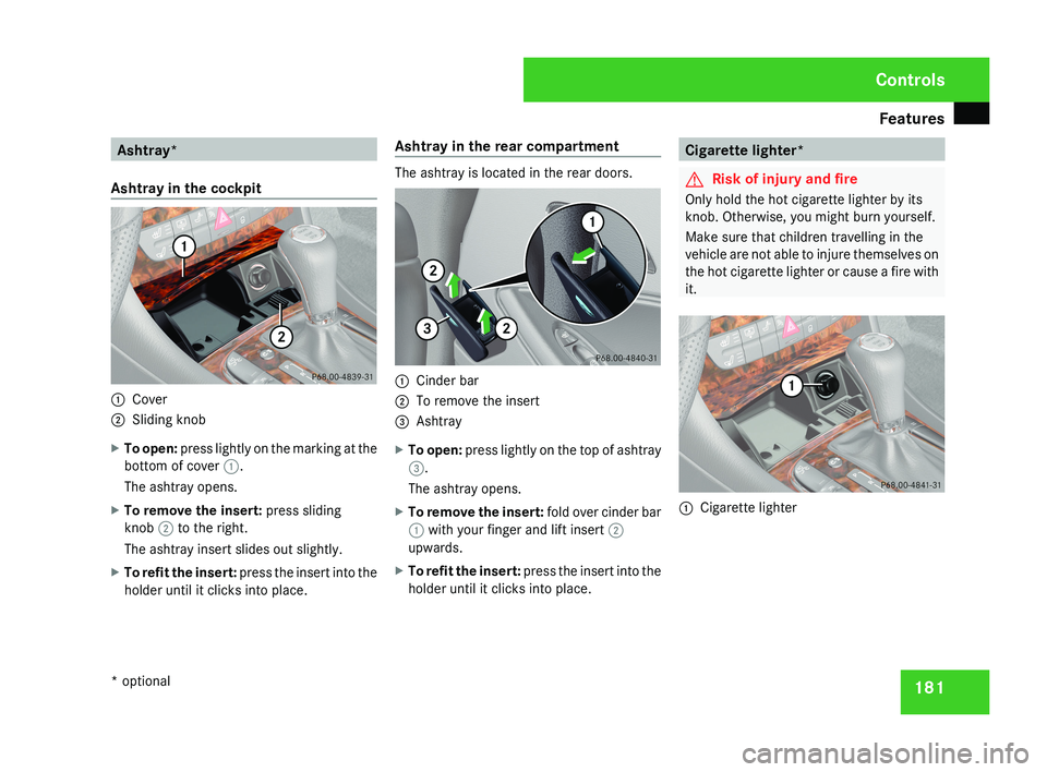
Ashtray in the cockpit 1
Cover
2 Sliding knob
X To open: press lightly on the marking at the
bottom of cover 1.
The ashtray opens.
X To remove the insert: press sliding
knob 2 to the right.
The ashtray insert slides out slightly.
X To refit the insert: press the insert into the
holder until it clicks into place. Ashtray in the rear compartment The ashtray is located in the rear doors.
1
Cinder bar
2 To remove the insert
3 Ashtray
X To open: press lightly on the top of ashtray
3.
The ashtray opens.
X To remove the insert: fold over cinder bar
1 with your finger and lift insert 2
upwards.
X To refit the insert: press the insert into the
holder until it clicks into place. Cigarette lighter*
G
Risk of injury and fire
Only hold the hot cigarette lighter by its
knob. Otherwise, you might burn yourself.
Make sure that children travelling in the
vehicle are not able to injure themselves on
the hot cigarette lighter or cause a fire with
it. 1
Cigarette lighter Controls
* optional
219_AKB; 2; 4, en-GB
mkalafa,
2007-11-13T09:28:36+01:00 - Seite 181
Page 185 of 329
Features
182
X
Make sure that the key is in position 2 in
the ignition lock.
X Press lightly on the marking at the bottom
of the cover.
The ashtray opens.
X Press in cigarette lighter 1.
Cigarette lighter 1 will pop out automati-
cally when the heating element is red-hot. 12V socket
The socket can be used for accessories with
a maximum power consumption of 180 watts.
X Make sure that the key is in position 2 in
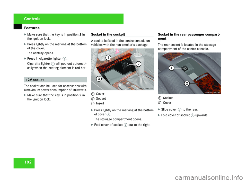
the ignition lock. Socket in the cockpit A socket is fitted in the centre console on
vehicles with the non-smoker's package.
1
Cover
2 Socket
3 Insert
X Press lightly on the marking at the bottom
of cover 1.
The stowage compartment opens.
X Fold cover of socket 2 out to the right. Socket in the rear passenger compart-
ment The rear socket is located in the stowage
compartment of the centre console.
1
Socket
2 Cover
X Slide cover 2 to the rear.
X Fold cover of socket 1 upwards.Controls
219_AKB; 2; 4, en-GB
mkalafa,
2007-11-13T09:28:36+01:00 - Seite 182
Page 186 of 329
Features
183Mobile phone*
G
Risk of accident
Observe the legal requirements of the
country in which you are currently driving
regarding operating mobile communica-
tions equipment in a vehicle.
If
it is permitted by law to operate commu-
nications equipment while the vehicle is in
motion, you must only do so when the traf-
fic situation allows. You could otherwise be
distracted from the traffic conditions,
cause an accident and injure yourself and
others.
Two-way radios and fax equipment used
without low-reflection exterior aerials can
interfere with the vehicle's electronics and
thereby jeopardise the operating safety of
the vehicle and your safety. You must there-
fore only use this equipment if it is correctly
connected to a separate reflection-free
exterior aerial. G
Risk of injury
Excessive electromagnetic radiation may
cause
damage to your health and the health
of others. Using an exterior aerial takes into
account current scientific discussions relating to the possible health risk posed by
electromagnetic fields.
i In
order to ensure optimum signal quality
for mobile phones and to minimise mutual
interference between the vehicle electron-
ics and mobile phones, Mercedes-Benz rec-
ommends the use of an approved exterior
aerial. An exterior aerial conducts the elec-
tromagnetic fields generated by a wireless
device to the exterior of the vehicle; the
field strength within the vehicle interior is
lower than in a vehicle that does not have
an exterior aerial.
i There are various mobile phone brackets
that may be fitted to your vehicle; in some
cases these are country-specific. You can
obtain these mobile phone brackets from a
qualified specialist workshop, e.g. a
Mercedes-Benz Service Centre. The func-
tions and services available when you use
the phone depend on your mobile phone
model and service provider.
The mobile phone bracket is in the armrest.
X Open the telephone compartment
(Y page 178). Inserting the mobile phone into the
mobile phone bracket If the mobile phone is inserted into the mobile
phone
bracket, you can only speak to the per-
son you are calling using the hands-free sys-
tem.
! Do not attempt to remove the mobile
phone and the telephone bracket together.
You could otherwise damage the mobile
phone bracket.
X Remove the cover of the aerial plug from
the
back of the mobile phone and keep it in
a safe place. Controls
* optional
219_AKB; 2; 4, en-GB
mkalafa,
2007-11-13T09:28:36+01:00 - Seite 183
Page 187 of 329
Features
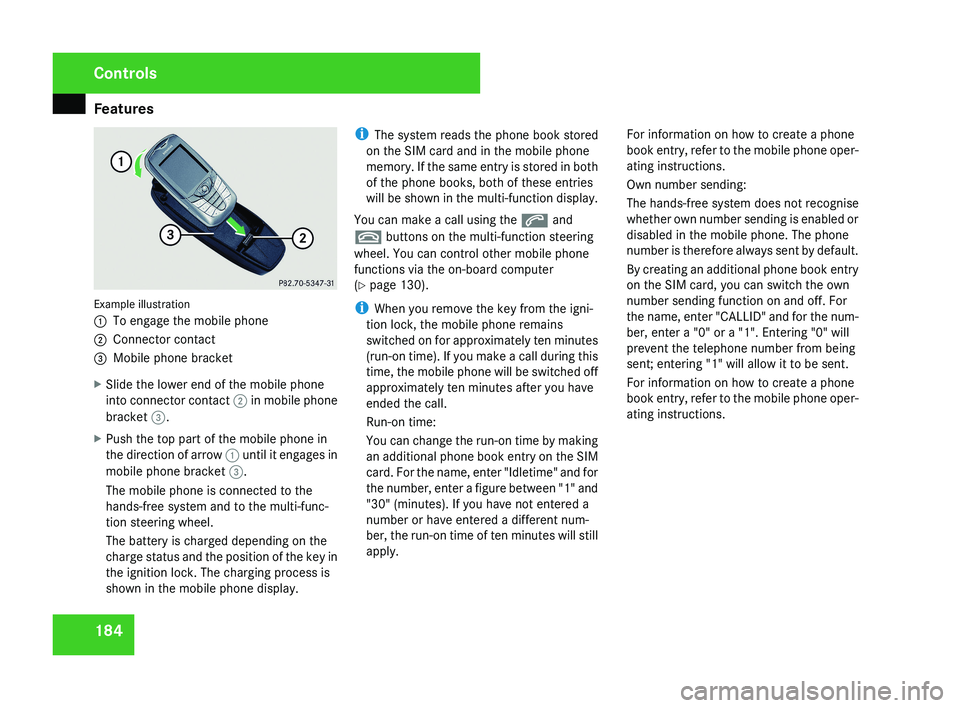
184Example illustration
1
To engage the mobile phone
2 Connector contact
3 Mobile phone bracket
X Slide the lower end of the mobile phone
into connector contact 2 in mobile phone
bracket 3.
X Push the top part of the mobile phone in
the direction of arrow 1 until it engages in
mobile phone bracket 3.
The mobile phone is connected to the
hands-free system and to the multi-func-
tion steering wheel.
The battery is charged depending on the
charge status and the position of the key in
the ignition lock. The charging process is
shown in the mobile phone display. i
The system reads the phone book stored
on the SIM card and in the mobile phone
memory. If the same entry is stored in both
of the phone books, both of these entries
will be shown in the multi-function display.
You can make a call using the s and
t buttons on the multi-function steering
wheel. You can control other mobile phone
functions via the on-board computer
(Y page 130).
i When you remove the key from the igni-
tion lock, the mobile phone remains
switched on for approximately ten minutes
(run-on time). If you make a call during this
time, the mobile phone will be switched off
approximately ten minutes after you have
ended the call.
Run-on time:
You can change the run-on time by making
an additional phone book entry on the SIM
card. For the name, enter "Idletime" and for
the number, enter a figure between "1" and
"30" (minutes). If you have not entered a
number or have entered a different num-
ber, the run-on time of ten minutes will still
apply. For information on how to create a phone
book entry, refer to the mobile phone oper-
ating instructions.
Own number sending:
The hands-free system does not recognise
whether own number sending is enabled or
disabled in the mobile phone. The phone
number is therefore always sent by default.
By creating an additional phone book entry
on the SIM card, you can switch the own
number sending function on and off. For
the name, enter "CALLID" and for the num-
ber, enter a "0" or a "1". Entering "0" will
prevent the telephone number from being
sent; entering "1" will allow it to be sent.
For information on how to create a phone
book entry, refer to the mobile phone oper-
ating instructions.
Controls
219_AKB; 2; 4, en-GB
mkalafa,
2007-11-13T09:28:36+01:00 - Seite 184
Page 188 of 329
Features
185
Removing the mobile phone from the
mobile phone bracket
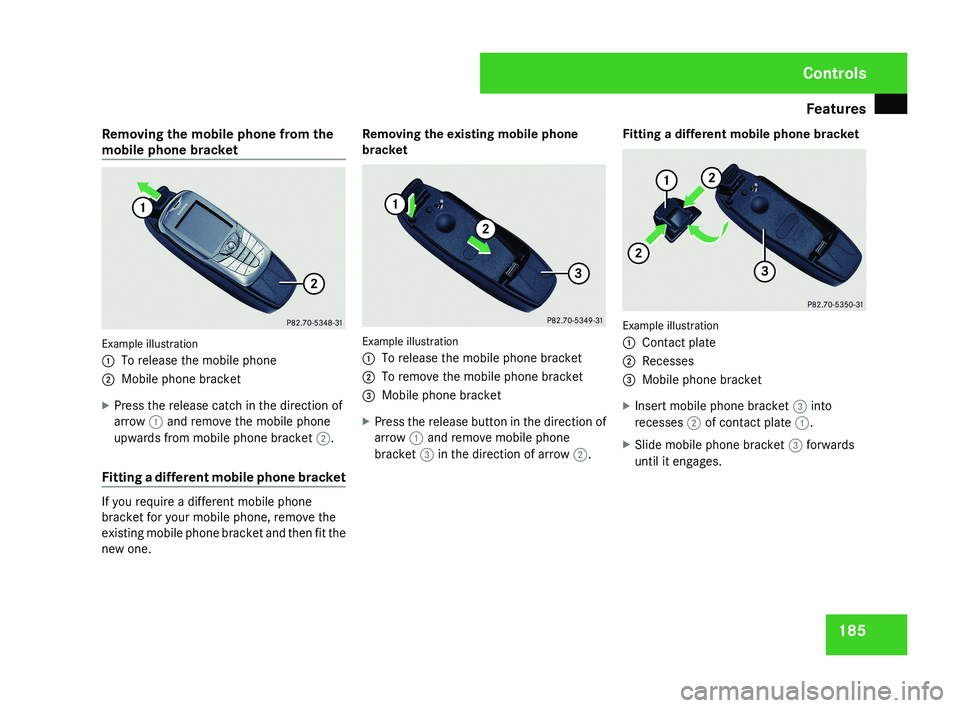
Example illustration
1
To release the mobile phone
2 Mobile phone bracket
X Press the release catch in the direction of
arrow 1 and remove the mobile phone
upwards from mobile phone bracket 2.
Fitting a different mobile phone bracket If you require a different mobile phone
bracket for your mobile phone, remove the
existing mobile phone bracket and then fit the
new one. Removing the existing mobile phone
bracket
Example illustration
1
To release the mobile phone bracket
2 To remove the mobile phone bracket
3 Mobile phone bracket
X Press the release button in the direction of
arrow 1 and remove mobile phone
bracket 3 in the direction of arrow 2. Fitting a different mobile phone bracket Example illustration
1
Contact plate
2 Recesses
3 Mobile phone bracket
X Insert mobile phone bracket 3 into
recesses 2 of contact plate 1.
X Slide mobile phone bracket 3 forwards
until it engages. Controls
219_AKB; 2; 4, en-GB
mkalafa,
2007-11-13T09:28:36+01:00 - Seite 185
Page 189 of 329
Features
186 Garage door opener*
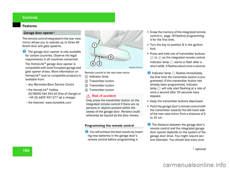
The remote control integrated in the rear-view
mirror allows you to operate up to three dif-
ferent door and gate systems.
i The garage door opener is only available
for certain countries. Observe the legal
requirements in all countries concerned.
The HomeLink ®
garage door opener is
compatible with most European garage and
gate opener drives. More information on
HomeLink ®
and/or compatible products is
available from:
R any Mercedes-Benz Service Centre
R the HomeLink ®
hotline
(0) 08000 466 354 65 (free of charge) or
+49 (0) 6839 907-277 (at a charge)
R the Internet: www.homelink.comRemote control in the rear-view mirror
1 Indicator lamp
2 Transmitter button
3 Transmitter button
4 Transmitter button
G Risk of accident
Only press the transmitter button on the
integrated remote control if there are no
persons or objects present within the
sweep of the garage door. Persons could
otherwise be injured as the door moves.
Programming the remote control
i You will achieve the best results by insert-
ing new batteries in the garage door's
remote control before programming it. X
Erase the memory of the integrated remote
control ( Y page 187)before programming
it for the first time.
X Turn the key to position 2 in the ignition
lock.
X Press and hold one of transmitter buttons
2 to 4 on the integrated remote control.
Indicator lamp 1 starts to flash after a
short while. It flashes about once a second.
i Indicator lamp 1 flashes immediately
the first time the transmitter button is pro-
grammed. If this transmitter button has
already been programmed, indicator
lamp 1 will only start flashing at a rate of
once a second after 20 seconds have
elapsed.
X Keep the transmitter buttons depressed.
X Point the garage door's remote control with
the transmitter towards the left-hand side
of the rear-view mirror from a distance of 5
to 20 cm.
i The distance between the garage door's
remote control and the integrated garage
door opener depends on the system of the
garage door drive. You might require sev-
eral attempts. You should test every posi-
Controls
* optional
219_AKB; 2; 4, en-GB
mkalafa,
2007-11-13T09:28:36+01:00 - Seite 186
Page 190 of 329
Features
187
tion for at least 20 seconds before trying
another position.
X Keep the transmitter button on the garage
door's
remote control depressed until indi-
cator lamp 1 starts to flash rapidly.
The programming was successful if indica-
tor lamp 1 flashes rapidly.
X Release the transmitter buttons on the
garage
door's remote control and the inte-
grated remote control.
If indicator lamp 1 goes out after approxi-
mately 20 seconds and did not flash rapidly
before this:
X Release the transmitter buttons on the
integrated and portable remote controls.
X Repeat the programming procedure. At the
same time change the distance between
the garage door's remote control and the
transmitter
buttons in the rear-view mirror.
i If the garage door system works with a
rolling code, after programming you must
synchronise the remote control integrated
in
the rear-view mirror with the garage door
system receiver.
You will find further information in the
garage door opening system's operating instructions, e.g. the sections on “Synchro-
nising the transmitter” or “Registering a
new
transmitter”. You can also call the hot-
line mentioned above.
Opening or closing the garage door Once programmed, the integrated remote
control
will assume the function of the garage
door system's remote control. Please read
the operating instructions for the garage door
system.
X Turn the key to position 2 in the ignition
lock.
X Press the transmitter button on the rear-
view mirror that you have programmed to
operate the garage door.
Garage door system with fixed code: indi-
cator lamp 1 lights up continuously.
Garage
door system with rolling code: indi-
cator lamp 1 flashes briefly and then lights
up for approximately two seconds. This is
repeated for up to 20 seconds.
i The transmitter will transmit a signal for
as long as the transmitter button is being
pressed. The transmission will be halted
after a maximum of 20 seconds and indi- cator lamp 1 will flash. Press the trans-
mitter button again if necessary.
Clearing the remote control memory X
Turn the key to position 2 in the ignition
lock.
X Press and hold transmitter buttons 2 and
4
for approximately 20 seconds until indi-
cator lamp 1 flashes rapidly.
The memory is cleared.
i You
should clear the remote control mem-
ory before selling the vehicle. Floormat* on the driver's side
G
Risk of accident
Make sure that there is sufficient clearance
around the pedals when floormats are
used, and that the floormats are properly
secured.
The
floormats must be secured at all times
using retainers and studs.
Before you drive off, make sure that the
floormats are secure and rectify if neces-
sary. A floormat which is not properly Controls
* optional
219_AKB; 2; 4, en-GB
mkalafa,
2007-11-13T09:28:36+01:00 - Seite 187 Z