MERCEDES-BENZ CLS COUPE 2018 Owners Manual
Manufacturer: MERCEDES-BENZ, Model Year: 2018, Model line: CLS COUPE, Model: MERCEDES-BENZ CLS COUPE 2018Pages: 589, PDF Size: 10.95 MB
Page 421 of 589
#
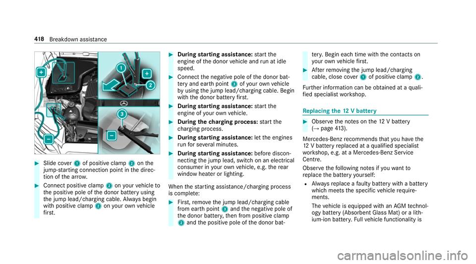
Slide co ver1 of positive clamp 2onthe
jump-s tarting connection point in the direc‐
tion of the ar row. #
Connect positive clamp 2onyour vehicle to
th e positive pole of the donor battery using
th e jump lead/charging cable. Alw ays begin
with positive clamp 2onyour ow nve hicle
fi rs t. #
During starting assi stance: start the
engine of the donor vehicle and run at idle
speed. #
Connect the negative pole of the donor bat‐
te ry and ear thpoint 3ofyour ow nve hicle
by using the jump lead/charging cable. Begin
with the donor battery firs t. #
During starting assi stance: start the
engine of your ow nve hicle. #
During thech arging process: start the
ch arging process. #
During starting assi stance: letthe engines
ru nfo r se veral minutes. #
During starting assi stance: before discon‐
necting the jump lead, switch on an electrical
consumer in your ow nve hicle, e.g. there ar
wind owheater or lighting.
When thest arting assis tance/charging process
is compl ete: #
First,re mo vethe jump lead/charging cable
from ear thpoint 3and the negative pole of
th e donor batter y,then from positive clamp
2 and the positive pole of the donor bat‐ te
ry. Begin ea chtime wi th the conta cts on
yo ur ow nve hicle firs t. #
Afterre moving the jump lead/charging
cable, close co ver1 of positive clamp 2.
Fu rther information can be obtained at a quali‐
fi ed specialist workshop. Re
placing the 12V battery #
Obser vethe no tes on the12 V battery
(→ page 413).
Me rcedes-Benz recommends that you ha vethe
12 V battery replaced at a qualified specialist
wo rkshop, e.g. at a Mercedes-Benz Service
Centre.
Obser vethefo llowing no tes if youwa ntto
re place the battery yourself:
R Alw aysre place a faulty bat tery with a battery
which meets the specific vehicle require‐
ments.
The vehicle is equipped with an AGMtech nol‐
ogy battery (Absorbent Glass Mat) or a li th‐
ium-ion batter y.Fu llve hicle functionality is 41 8
Breakdown assis tance
Page 422 of 589
only guaranteed with an
AGM battery or lith‐
ium-ion batter y.Fo r saf etyre asons,
Mercedes-Benz recommends that you on ly
use bat teries which ha vebeen tested and
appr ovedfo ryo ur vehicle byMercedes-Benz.
R Carryove r de tach able parts, such as vent
hoses, elbow fittings or term inal co vers, from
th e battery being replaced.
R Make sure that theve nt hose is al ways con‐
nected tothe original opening on the side of
th e batter y. Fit any
existing or supplied cell caps.
Otherwise, gases or battery acid could
escape.
R Make sure that de tach able parts are recon‐
nected in the same way. To
w- starting or towing away Pe
rm itted towing me thods Mercedes-Benz
recommends transporting your
ve hicle in the case of a breakdown, rath er than
to wing it away. Fo
rto wing, use a tow rope or tow bar with bo th
axles on the ground. Do not use tow bar sys‐
te ms.
* NO
TEDama getotheve hicle due to tow‐
ing away incor rectly #
Obser vethe instructions and no tes on
to wing away. Breakdown assis
tance 419
Page 423 of 589
Pe
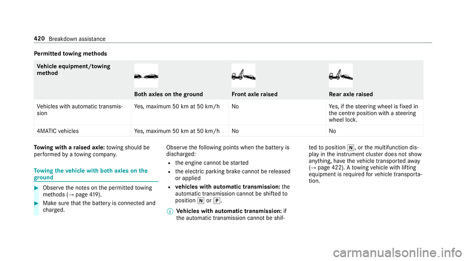
rm itted towing me thods Ve
hicle equipment/ towing
me thod Bo
th axles on thegr ound Fr
ont axle raised Re
ar axle raised
Ve hicles with automatic transmis‐
sion Ye
s, maximum 50 km at 50 km/h No Yes, if thesteering wheel is fixe d in
th e cent reposition with a steering
wheel loc k.
4MATIC vehicles Yes, maximum 50 km at 50 km/h No NoTo
wing with a raised axle: towing should be
per form ed byato wing compan y. To
wing theve hicle with bo thaxles on the
gr ound #
Obser vethe no tes on the permitted towing
me thods (→ page419). #
Makesure that the battery is connected and
ch arge d. Obser
vethefo llowing points when the battery is
dischar ged:
R the engine cann otbe star ted
R the electric parking brake cann otbe released
or applied
R vehicles with automatic transmission: the
automatic transmission cannot be shif tedto
position iorj.
% Vehicles with automatic transmission: if
th e automatic transmission cann otbe shif‐ te
dto position i, orthe multifunction dis‐
play in the instrument clus ter does not show
anything, ha vetheve hicle transpor tedaw ay
( → page 422). A towing vehicle with lifting
equipment is requiredforve hicle transpor ta‐
tion. 420
Breakdown assi stance
Page 424 of 589
*
NO
TEDama gedue to to wing away at
exc essively high speeds or over long dis‐
ta nces The driv
etra in could be damaged when tow‐
ing at excessively high speeds or over long
dis tances. #
Atowing speed of 50 km/h must not
be exc eeded. #
Atowing dis tance of 50 km must not be
exc eeded. &
WARNING Risk of accident when towing
a ve hicle which is too heavy
If th eve hicle being tow- star ted or towed
aw ay is heavier than the permissible gross
mass, thefo llowing situations can occur:
R theto wing eye may become de tach ed.
R the car/t railer combination may swer ve
or eve nove rturn. #
If ano ther vehicle is tow- star ted or
to we daw ay, its weight must not exceed th
e permissible gross mass of your own
ve hicle. If a
vehicle must be tow star ted or towe daw ay,
its permissible gross mass must not exceed the
permissible gross mass of theto wing vehicle. #
Information on the permissible gross mass of
th eve hicle can be found on theve hicle iden‐
tification plate (→ page 450). #
Vehicles with automatic transmission: do
not open the driver's door or front passenger
door, otherwise the automatic transmission
automatically shifts toposition j. #
Fittheto wing eye (→ page 423). #
Fasten theto w bar.
* NO
TEDama gedue toincor rect connec‐
tion #
Only connect theto w rope or tow bar to
th eto wing eyes. #
Deactivate the automatic locking mechanism
(→ page 75). #
Do not activate the HOLD function. #
Deactivate tow- aw ay protection (→ page91). #
Deactivate Active Brake Assi st (→page 191). #
Vehicles with automatic transmission:
shift the automatic transmission toposition
i. #
Release the electric parking brake. &
WARNING Risk of accident due tolimi‐
te d saf ety-re lated functions during the
to wing process
Saf ety-re lated functions are limited or no lon‐
ge rav ailable in thefo llowing situations:
R the ignition is switched off.
R the brake sy stem or po werst eering sys‐
te m is malfunctioning.
R the energy supply or the on-board electri‐
cal sy stem is malfunctioning.
When your vehicle is then towe daw ay, signif‐
icantly more ef fort may be requ ired tosteer
and brake than is no rmally requ ired. Breakdown assis
tance 421
Page 425 of 589
#
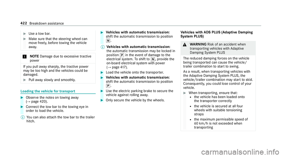
Use a tow bar. #
Make sure that thesteering wheel can
mo vefreely, before towing theve hicle
aw ay. *
NO
TEDama gedue toexcessive tracti ve
po wer If
yo u pull away sharpl y,the tractive po wer
may be too high and theve hicles could be
damaged. #
Pull away slowly and smoo thly. Loading the
vehicle for transport #
Obser vethe no tes on towing away
( → page 420). #
Connect theto w bar totheto wing eye in
order toload theve hicle.
% You can also attach theto w bar tothe trailer
hitch. #
Vehicles with automatic transmission:
shift the automatic transmission toposition
i.
% Ve
hicles with automatic transmission:
th e automatic transmission may be loc ked in
position jintheeve nt of dama getothe
electrical sy stem. Toshift toi , pr ovide the
on-board electrical sy stem with po wer
( → page 417). #
Load theve hicle onto the transpor ter. #
Vehicles with automatic transmission:
shift the automatic transmission toposition
j. #
Use the electric parking brake tosecure the
ve hicle against rolling away. #
Only secure theve hicle bythe wheels. Ve
hicles with ADS PLUS (Adaptive Damping
Sy stem PLUS) &
WARNING Risk of an accident when
transporting vehicles with Adaptive
Damping Sy stem PLUS
The reduced damping forc es on theve hicle
being transpor ted can cause theve hicle/
trailer combination tostart toswing.
As a result, when transporting vehicles with
th eAd aptive Damping Sy stem PLUS, the
ve hicle/trailer combination may start toskid.
Consequentl y,yo u could lose cont rol of your
ve hicle. #
When transporting, ensure that:
R theve hicle has been loaded onto
th e transpor ter cor rectly
R theve hicle is secured at all four
wheels with suitable tensioning
st ra ps
R the maximum permissible speed of
60 km/h is not exceeded when
transporting 422
Breakdown assis tance
Page 426 of 589
*
NO
TEDama getotheve hicle from secur‐
ing it incor rectly #
After loading, theve hicle must be
secured on all four wheels. Otherwise,
th eve hicle could be damaged. #
A minimum dis tance of 20 cm up wards
and 10cm down wards must be kept to
th e transport platform. #
Secure theve hicle on all four wheels af ter
loading.
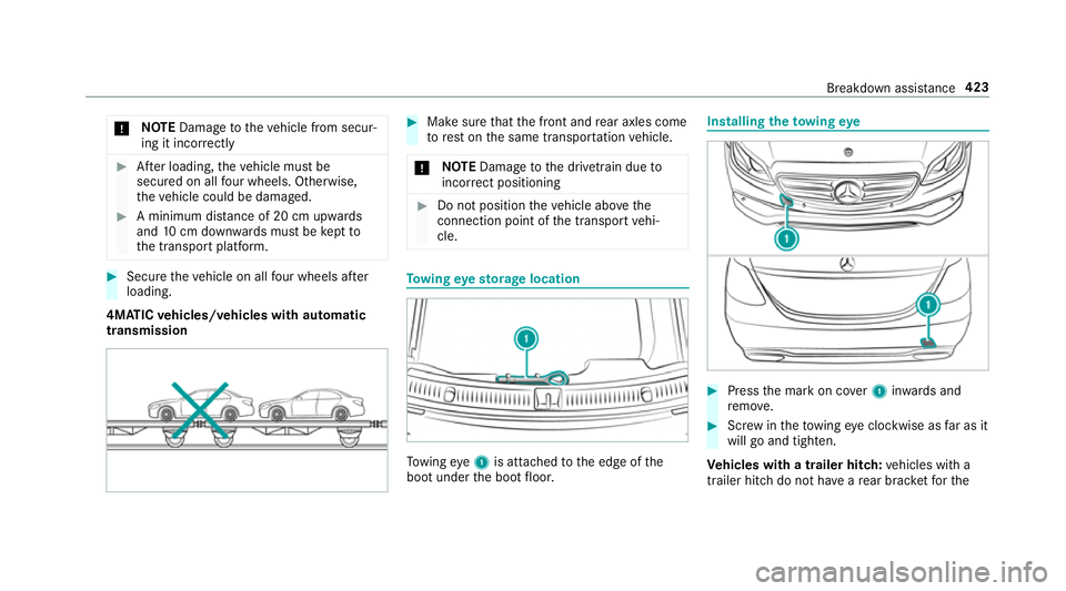
4MATIC vehicles/ vehicles with automatic
transmission #
Make sure that the front and rear axles come
to rest on the same transpor tation vehicle.
* NO
TEDama getothe driv etra in due to
incor rect positioning #
Do not position theve hicle abo vethe
connection point of the transport vehi‐
cle. To
wing eyesto rage location To
wing eye1 is attached tothe edge of the
boot under the boot floor. Installing
theto wing eye #
Press the mark on co ver1 inwa rds and
re mo ve. #
Screw intheto wing eyeclockwise as far as it
will go and tighten.
Ve hicles with a trailer hitch: vehicles with a
trailer hitch do not ha veare ar brac ketfo rthe Breakdown assis
tance 423
Page 427 of 589
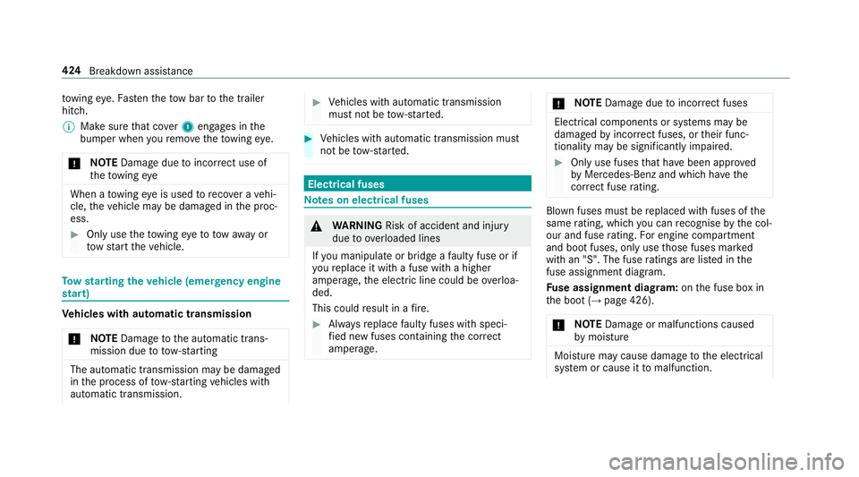
to
wing eye. Fasten theto w bar tothe trailer
hitch.
% Make sure that co ver1 engages in the
bumper when youre mo vetheto wing eye.
* NO
TEDama gedue toincor rect use of
th eto wing eye When a
towing eye is used toreco ver a vehi‐
cle, theve hicle may be damaged in the proc‐
ess. #
Only use theto wing eyeto to waw ay or
to w start theve hicle. To
w starting theve hicle (eme rgency engine
st art) Ve
hicles with automatic transmission
* NO
TEDama getothe automatic trans‐
mission due to tow-starting The automatic transmission may be damaged
in the process of tow- starting vehicles with
automatic transmission. #
Vehicles with automatic transmission
must not be tow- star ted. #
Vehicles with automatic transmission must
not be tow- star ted. Electrical fuses
Note
s on electrical fuses &
WARNING Risk of accident and inju ry
due to ov erloaded lines
If yo u manipulate or bridge a faulty fuse or if
yo ure place it with a fuse with a higher
amperage, the electric line could be overloa‐
ded.
This could result in a fire. #
Alw aysre place faulty fuses with speci‐
fi ed new fuses conta iningthe cor rect
amperage. *
NO
TEDama gedue toincor rect fuses Electrical components or sy
stems may be
damaged byincor rect fuses, or their func‐
tionality may be significant lyimpaired. #
Only use fuses that ha vebeen appr oved
by Mercedes-Benz and which ha vethe
cor rect fuse rating. Blown fuses mu
stbe replaced with fuses of the
same rating, which you can recognise bythe col‐
our and fuse rating. For engine compartment
and boot fuses, only use those fuses mar ked
with an "S". The fuse ratings are li sted in the
fuse assignment diagram.
Fu se assignment diag ram: onthe fuse box in
th e boot (→ page 426).
* NO
TEDama geor malfunctions caused
by moisture Moisture may cause dama
getothe electrical
sy stem or cause it tomalfunction. 424
Breakdown assi stance
Page 428 of 589
#
When the fuse box is open, make sure
th at no moisture can enter the fuse
box. #
When closing the fuse box, make sure
th at the seal of the lid is positioned cor‐
re ctly on the fuse box. If
th e newly inser ted fuse also blo ws, ha vethe
cause traced and rectified at a qualified special‐
ist workshop, e.g. a Mercedes-Benz Service
Centre.
Ensure thefo llowing before replacing a fuse:
R The vehicle is secured against rolling away.
R All electrical consumers are switched off.
R The ignition is switched off.
The electrical fuses are located in various fuse
bo xes:
R Fuse box in the engine compartment on the
driver's side (→ page 425)
R Fuse box on the driver's side of the dash‐
board (→ page 426) R
Fuse box in the front passenger foot we ll
(→ page 426)
R Fuse box in the boot on theright-hand side
of theve hicle, when vie wed in the direction
of tr avel (→ page 426) Opening and closing
the fuse box in the
engine compa rtment Re
quirements:
R You need a dry clo thand a sc rewdriver.
Obser vethe no tes on electrical fuses
(→ page 424).
Opening &
WARNING Risk of inju ryfrom using the
windscreen wipers while the engine bon‐
net is open
When the engine bonn etis open, and the
windscreen wipers are set in motion, you can
be trapped bythe wiper linkage. #
Alw ays switch off the windscreen wip‐
ers and ignition before opening the
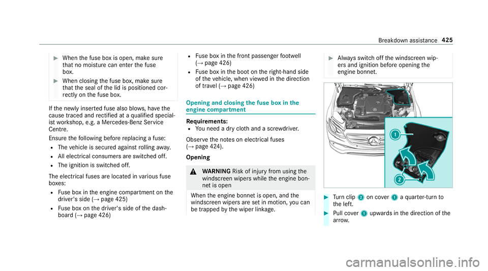
engine bonn et. #
Turn clip 2on co ver1 aqu arter-turn to
th e left. #
Pull co ver1 upwards in the direction of the
ar row. Breakdown assis
tance 425
Page 429 of 589
#
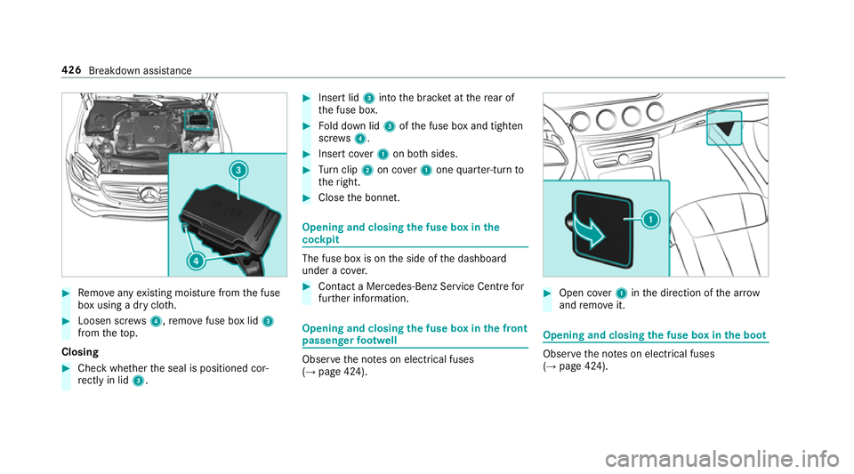
Remo veany existing moisture from the fuse
box using a dry clo th.#
Loosen scr ews4, remo vefuse box lid 3
from theto p.
Closing #
Check whe ther the seal is positioned cor‐
re ctly in lid 3. #
Insert lid 3into the brac ket at there ar of
th e fuse box. #
Fold down lid 3ofthe fuse box and tighten
scr ews4. #
Insert co ver1 on bo thsides. #
Turn clip 2on co ver1 one quarter-turn to
th eright. #
Close the bonn et. Opening and closing
the fuse box in the
cockpit The fuse box is on
the side of the dashboard
under a co ver. #
Con tact a Mercedes-Benz Service Centre for
fur ther information. Opening and closing
the fuse box in the front
passenger foot we ll Obser
vethe no tes on electrical fuses
(→ page 424). #
Open co ver1 inthe direction of the ar row
and remo veit. Opening and closing
the fuse box in the boot Obser
vethe no tes on electrical fuses
(→ page 424). 426
Breakdown assis tance
Page 430 of 589
#
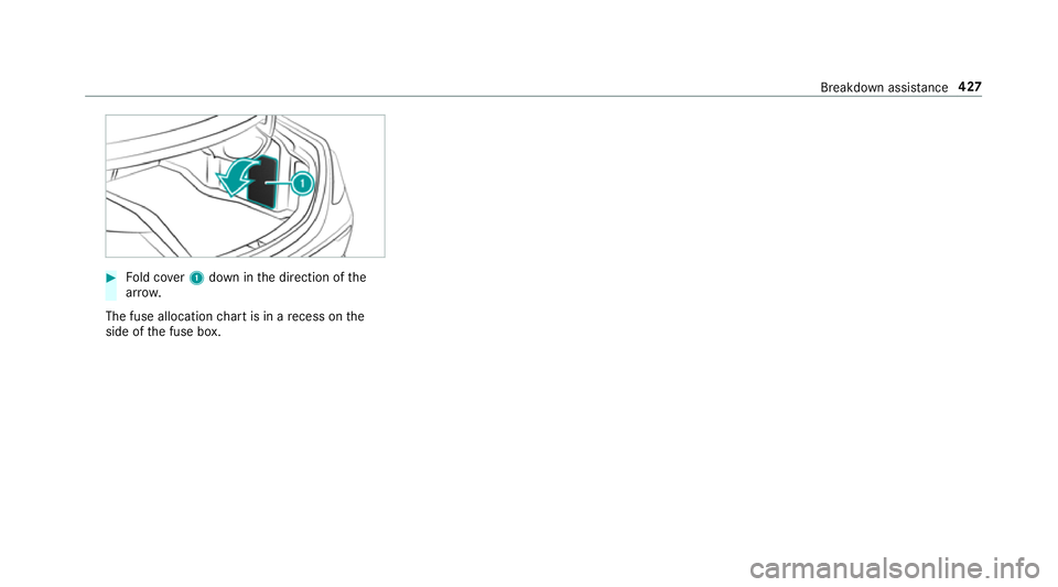
Fold co ver1 down in the direction of the
ar row.
The fuse allocation chart is in a recess on the
side of the fuse box. Breakdown assis
tance 427