display MERCEDES-BENZ E-Class 2001 W210 Owner's Manual
[x] Cancel search | Manufacturer: MERCEDES-BENZ, Model Year: 2001, Model line: E-Class, Model: MERCEDES-BENZ E-Class 2001 W210Pages: 421, PDF Size: 20.52 MB
Page 358 of 421
355 Towing the vehicle
Te ch n ica l
data Instruments
and controlsOperation DrivingInstrument
cluster displayPractical hintsCar care Index We recommend that the vehicle be transported using
flat bed equipment. This method is preferable to other
types of towing.
Important!
To prevent damage during transport, do not tie down
vehicle by its chassis or suspension parts.
The vehicle may be towed with all wheels on the ground
and the selector lever in position “N” for distances up to
30 miles (50 km) and at a speed not to exceed 30 mph
(50 km / h). The electronic key must be in starter switch
position 2.
To be certain to avoid a possibility of damage to the
transmission, however, we recommend the drive shaft
be disconnected at the rear axle drive f lange for any
towing beyond a short tow to a nearby garage.
Do not tow with sling-type equipment. Towing with
sling-type equipment over bumpy roads will damage
radiator and supports.
Use wheel lift, dolly, or flat bed equipment, with
electronic key in starter switch turned to position 0.Note:
To signal turns while being towed with hazard warning
flasher in use, turn electronic key in starter switch to
position 2 and activate combination switch for left or
right turn signal in usual manner – only the selected
turn signal will operate.
Upon canceling the turn signal, the hazard warning
flasher will operate again.
Caution!
If the vehicle is towed with the front axle raised, the
engine must be shut off (electronic key in starter switch
position 0 or 1). Otherwise, the ESP will immediately be
engaged and will apply the rear wheel brakes.
Switch off the tow-away alarm (see “VEHICLE” under
“Individual settings” on page 144) as well as the ESP
(see page 274).
Wa r n i n g !
With the engine not running, there is no power
assistance for the braking and steering systems. In
this case, it is important to keep in mind that a
considerably higher degree of effort is necessary to
brake and steer the vehicle.
Page 359 of 421
356 Exterior lamps
Te ch n ica l
data Instruments
and controlsOperation DrivingInstrument
cluster displayPractical hintsCar care Index
Exterior lamps
Headlamp adjustment
Correct headlamp adjustment is extremely important.
Check and readjust headlamps at regular intervals and
when a bulb has been replaced.Replacing bulbs
Notes:
To prevent a possible electrical short circuit, switch off
lamp prior to replacing a bulb.
When replacing bulbs, install only 12 volt bulbs with
the specified watt rating.
When replacing halogen bulbs do not touch glass
portion of bulb with bare hands. Use plain paper or a
clean cloth.
If the newly installed bulb does not light up, switch the
lamp off and on again. If the bulb still does not light up,
have the system checked at an authorized
Mercedes-Benz Center.
Wa r n i n g !
Bulbs and bulb holders can be very hot. Allow the
lamp to cool down before changing a bulb.
Halogen lamps contain pressurized gas. A bulb can
explode if you:
• touch or move it when hot,
•drop the bulb,
•scratch the bulb.Wear eye and hand protection.
Wa r n i n g !
Because of high voltage in Xenon lamps, it is
dangerous to replace the bulb or repair the lamp
and its components. We recommend that you have
such work done by a qualified technician.
Page 360 of 421
357 Exterior lamps
Te ch n ica l
data Instruments
and controlsOperation DrivingInstrument
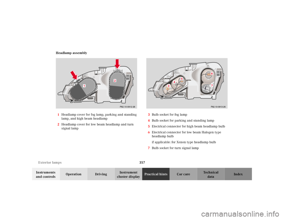
cluster displayPractical hintsCar care Index Headlamp assembly
1Headlamp cover for fog lamp, parking and standing
lamp, and high beam headlamp
2Headlamp cover for low beam headlamp and turn
signal lamp3Bulb socket for fog lamp
4Bulb socket for parking and standing lamp
5Electrical connector for high beam headlamp bulb
6Electrical connector for low beam Halogen type
headlamp bulb
if applicable: for Xenon type headlamp bulb
7Bulb socket for turn signal lamp
P82.10-0912-26
2
1
P82.10-0913-26
3
4
5
67
Page 361 of 421
358 Exterior lamps
Te ch n ica l
data Instruments
and controlsOperation DrivingInstrument
cluster displayPractical hintsCar care Index
Bulbs for high and low beam
H7 (55 W)
Open hood.
Press the clip together (arrow) and remove headlamp
cover (1 or 2).
Pull electrical connector off.
Unclip the retainer spring and take out the bulb.
Insert the new bulb so that the base locates in the
recess on the holder.
Clip in retainer springs and plug the connector onto the
bulb.
Align headlamp cover (1 or 2) and click into place.
Xenon (optional)
Bulb for low beamTurn signal lamp
(2357 NA [28.5 / 8.3 W] (Yellow))
Open hood.
Press the clip together (arrow) and remove headlamp
cover (2).
Twist bulb socket (7) counterclockwise and pull out.
Push bulb into socket, turn counterclockwise and
remove.
Insert new bulb in socket, push in and twist clockwise.
Reinstall bulb socket.
Align headlamp cover (2) and click into place.
Wa r n i n g !
Because of high voltage in Xenon lamps, it is
dangerous to replace the bulb or repair the lamp
and its components. We recommend that you have
such work done by a qualified technician.
Page 362 of 421
359 Exterior lamps
Te ch n ica l
data Instruments
and controlsOperation DrivingInstrument
cluster displayPractical hintsCar care Index Front fog lamp
H1 (55W)
Open hood.
Press the clip together (arrow) and remove headlamp
cover (1).
Pull electrical connector off.
Unclip the retainer spring and take out the bulb.
Insert the new bulb so that the base locates in the
recess on the holder.
Clip in retainer spring and plug the connector onto the
bulb.
Align headlamp cover (1) and click into place.Parking and standing lamp
W 5W
Open hood.
Press the clip together (arrow) and remove headlamp
cover (1).
Twist bulb socket (4) counterclockwise and pull out.
Push bulb into socket, turn counterclockwise and
remove.
Insert new bulb in socket, push in and twist clockwise.
Reinstall bulb socket.
Align headlamp cover (1) and click into place.
Page 363 of 421
360 Exterior lamps
Te ch n ica l
data Instruments
and controlsOperation DrivingInstrument
cluster displayPractical hintsCar care Index
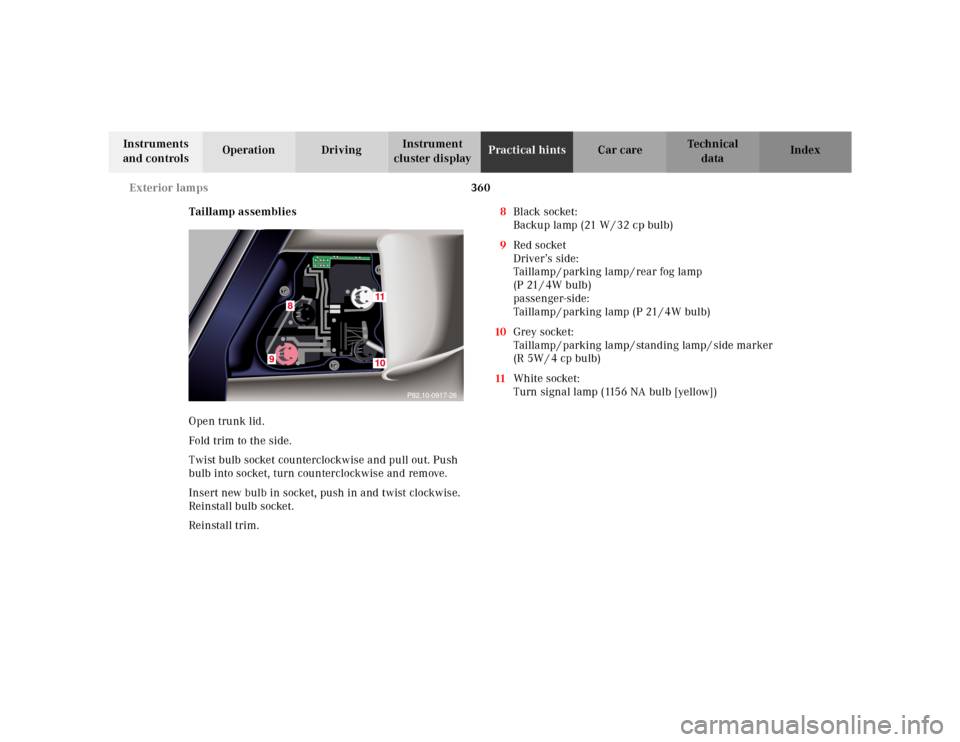
Taillamp assemblies
Open trunk lid.
Fold trim to the side.
Twist bulb socket counterclockwise and pull out. Push
bulb into socket, turn counterclockwise and remove.
Insert new bulb in socket, push in and twist clockwise.
Reinstall bulb socket.
Reinstall trim. 8Black socket:
Backup lamp (21 W / 32 cp bulb)
9Red socket
Driver’s side:
Taillamp / parking lamp / rear fog lamp
(P 21 / 4W bulb)
passenger-side:
Taillamp / parking lamp (P 21 / 4W bulb)
10Grey socket:
Taillamp / parking lamp / standing lamp / side marker
(R 5W / 4 cp bulb)
11White socket:
Turn signal lamp (1156 NA bulb [yellow])
P82.10-0917-26
9
8
1110
Page 364 of 421
361 Exterior lamps
Te ch n ica l
data Instruments
and controlsOperation DrivingInstrument
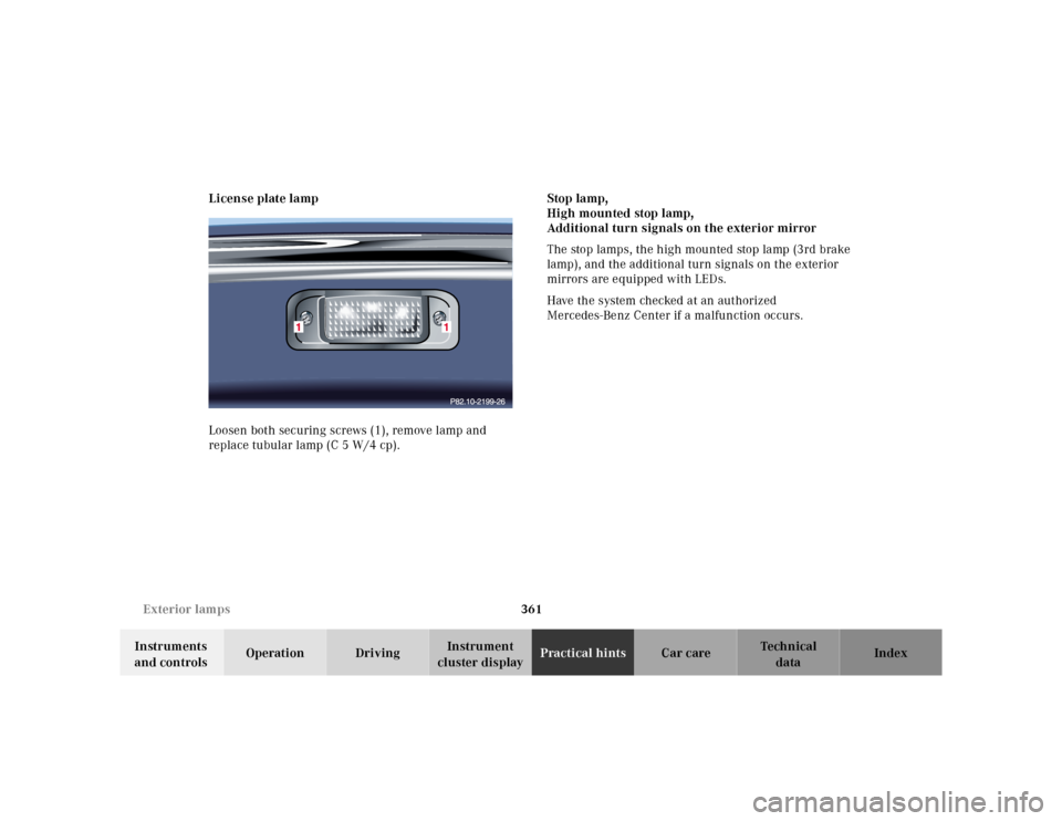
cluster displayPractical hintsCar care Index License plate lamp
Loosen both securing screws (1), remove lamp and
replace tubular lamp (C 5 W/4 cp).Stop lamp,
High mounted stop lamp,
Additional turn signals on the exterior mirror
The stop lamps, the high mounted stop lamp (3rd brake
lamp), and the additional turn signals on the exterior
mirrors are equipped with LEDs.
Have the system checked at an authorized
Mercedes-Benz Center if a malfunction occurs.
Page 365 of 421
362 Trunk lamp
Te ch n ica l
data Instruments
and controlsOperation DrivingInstrument
cluster displayPractical hintsCar care Index
Standby bulb function
The rear fog lamp, dimmed, will act as a replacement
lamp, if the bulb in the inner left-hand taillamp stops
working.
The inner taillamp acts as a replacement for the right or
left-hand bulb of the outer taillamp, if it stops working
as a parking lamp.
Notes:
The multifunction display will indicate that a bulb has
failed. See Malfunction and warning messages on
page 303.Trunk lamp
The trunk lamp will switch off after approximately
10 minutes if the trunk lid is left open.
Page 366 of 421
363 Electronic main key
Te ch n ica l
data Instruments
and controlsOperation DrivingInstrument
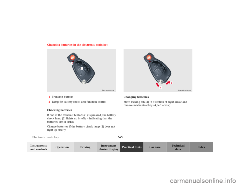
cluster displayPractical hintsCar care Index Changing batteries in the electronic main key
1Transmit buttons
2Lamp for battery check and function control
Checking batteries
If one of the transmit buttons (1) is pressed, the battery
check lamp (2) lights up briefly – indicating that the
batteries are in order.
Change batteries if the battery check lamp (2) does not
light up briefly.Changing batteries
Move locking tab (3) in direction of right arrow and
remove mechanical key (4, left arrow).
P80.20-2201-26
1
2
P80.35-2029-26
4
3
Page 367 of 421
364 Electronic main key
Te ch n ica l
data Instruments
and controlsOperation DrivingInstrument
cluster displayPractical hintsCar care Index
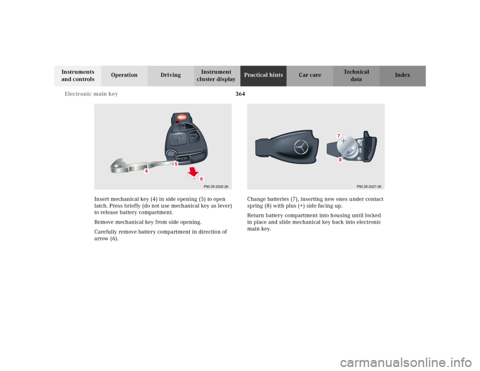
Insert mechanical key (4) in side opening (5) to open
latch. Press briefly (do not use mechanical key as lever)
to release battery compartment.
Remove mechanical key from side opening.
Carefully remove battery compartment in direction of
arrow (6).Change batteries (7), inserting new ones under contact
spring (8) with plus (+) side facing up.
Return battery compartment into housing until locked
in place and slide mechanical key back into electronic
main key.
P80.35-2025-26
5
4
6
P80.35-2027-26
78