key MERCEDES-BENZ E-Class CABRIOLET 2017 A207 Owner's Manual
[x] Cancel search | Manufacturer: MERCEDES-BENZ, Model Year: 2017, Model line: E-Class CABRIOLET, Model: MERCEDES-BENZ E-Class CABRIOLET 2017 A207Pages: 322, PDF Size: 7.97 MB
Page 274 of 322
GWARNING
The tire sealant is harmful and causes irrita-
tion. It must not come into contact with your
skin, eyes or clothing or be swallowed. Do not inhale TIREFIT fumes. Keep tire sealant away
from children. There is a risk of injury.
If you come into contact with the tire sealant,
observe the following:
RRinse off the tire sealant from your skin
immediately with water.
RIf the tire sealant comes into contact with
your eyes, immediately rinse them thor-
oughly with clean water.
RIf tire sealant is swallowed, immediately
rinse your mouth out thoroughly and drink
plenty of water. Do not induce vomiting,
and seek medical attention immediately.
RImmediately change out of clothing which
has come into contact with tire sealant.
RIf an allergic reaction occurs, seek medical
attention immediately.
!Do not operate the tire inflation compressor
for longer than eight minutes at a time without a break. It may otherwise overheat.
The tire inflation compressor can be operated
again once it has cooled down.
Comply with the manufacturer’s safety instruc-
tions on the sticker on the tire inflation com-
pressor.
Using the TIREFIT kit
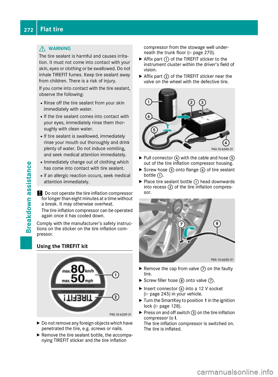
XDo not remove any foreign objects which have
penetrated the tire, e.g. screws or nails.
XRemove the tire sealant bottle, the accompa-
nying TIREFIT sticker and the tire inflation compressor from the stowage well under-
neath the trunk floor (
Ypage 270).
XAffix part
:of the TIREFIT sticker to the
instrument cluster within the driver's field of
vision.
XAffix part ;of the TIREFIT sticker near the
valve on the wheel with the defective tire.
XPull connector ?with the cable and hose A
out of the tire inflation compressor housing.
XScrew hose Aonto flange Bof tire sealant
bottle :.
XPlace tire sealant bottle :head downwards
into recess ;of the tire inflation compres-
sor.
XRemove the cap from valve Con the faulty
tire.
XScrew filler hose Donto valve C.
XInsert connector ?into a 12 V socket
(Ypage 245) in your vehicle.
XTurn the SmartKey to position 1in the ignition
lock (Ypage 128).
XPress on and off switch =on the tire inflation
compressor to I.
The tire inflation compressor is switched on.
The tire is inflated.
272Flat tire
Breakdown assistance
Page 278 of 322
Rinseany acid spills immediately
wit hclear water. Contac t aphysician
if necessary.
Wear eye protection .
Keepchildren away.
Observ ethis Operator's Manual.
Fo rsafet yreasons, Mercedes-Ben zrecom-
mends that you only use batterie swhic hhav e
been tested and approve dfor your vehicl eby
Mercedes-Benz. These batterie sprovide
increased impact protection to preven tvehicl e
occupant sfrom suffering acid burn sshould th e
battery be damaged in th eevent of an accident.
In order for th ebattery to achiev eth emaximum
possibl eservic elife ,it mus talways be suffi-
ciently charged.
Lik eother batteries, th evehicl ebattery may
discharge ove rtime if you do no tuse th evehicle.
In this case, hav eth ebattery disconnected at a
qualified specialist workshop. You can also
charge th ebattery wit h acharge rrecommended
by Mercedes-Benz. Contac t aqualified special-
ist workshop for further information .
Hav eth ebattery condition of charge checke d
mor efrequentl yif you use th evehicl emainly for
short trips or if you leav eit standing idle for a
lengthy period. Consult aqualified specialist
workshop if you wish to leav eyour vehicl e
parked for alon gperiod of time.
Remove th eSmartKey if you park th evehicl e
and do no trequire any electrical consumers.
The vehicl ewill then use ver ylittl eenergy, thus
conserving battery p
ower
.
If th epower suppl yhas been interrupted, e.g. if
you reconnect th ebattery, you will hav eto :
Rset th eclock .Information on setting th eclock
can be foun din th eDigital Operator's Manual
On vehicles wit h amultimedia system, th e
time is set automatically.
Rreset th efunction for foldin gth eexterio rmir -
ror sin/out automatically, by foldin gth emir -
ror sout once (
Ypage 106)
Charging the battery
GWARNING
During charging and jump-starting ,explosive
gase scan escape from th ebattery. There is a
ris kof an explosion .
Particularly avoi dfire, open flames, creating
sparks and smoking. Ensur ethere is sufficien t
ventilation while charging and jump-starting .
Do no tlean ove r abattery.
GWARNIN G
Battery acid is caustic. There is aris kof injury.
Avoid contact wit hskin, eyes or clothing .Do
no tinhale any battery gases. Do no tlean ove r
th ebattery. Kee pchildren away from batter-
ies. Wash away battery acid immediately wit h
plenty of clean water and seek medical atten -
tion .
GWARNIN G
A discharged battery can freez eat tempera-
tures belo wfreezing point. When jump-start -
ing th evehicl eor charging th ebattery, gase s
can escape from th ebattery. There is aris kof
an explosion .
Allow th efrozen battery to thaw out before
charging it or jump-starting .
!Only use battery chargers wit h amaximum
charging voltag eof 14.8 V.
!Only charge th ebattery usin gth ejump-
starting connection point.
The jump-starting connection poin tis in th e
engin ecompartmen t (
Ypage 278).
XOpen thehood.
XConnect th ebattery charge rto th epositive
termina land ground poin tin th esam eorder
as when connecting th edonor battery in th e
jump-starting procedure (
Ypage 278).
If th eindicator/warning lamp sdo no tligh tup at
low temperatures ,it is ver ylikely that th edis-
charge dbattery has frozen .In this case, you
may neither charge th ebattery no rjump-start
th evehicle. The servic elife of athawed-out bat -
tery may be shorter. The starting characteristics
may be impaired, especially at low tempera-
276Battery (vehicle)
Breakdown assistance
Page 281 of 322
Do not start the vehicle using a rapid charging device. If your vehicle's battery is discharged, the
engine can be jump-started from another vehicle or from a second battery using jumper cables.
Observe the following points:
RThe battery is not accessible in all vehicles. If the other vehicle's battery is not accessible, jump-
start the vehicle using a second battery or a jump-starting device.
RYou may only jump-start the vehicle when the engine and exhaust system are cold.
ROnly jump-start from batteries with a 12 V voltage rating.
ROnly use jumper cables which have a sufficient cross-section and insulated terminal clamps.
RIf the battery is fully discharged, leave the battery that is being used to jump-start connected for
a few minutes before attempting to start. This charges the battery slightly.
RMake sure that the two vehicles do not touch.
Make sure that:
Rthe jumper cables are not damaged.
Rwhen the jumper cables are connected to the battery, uninsulated sections of the terminal clamp
do not come into contact with other metal sections.
Rthe jumper cables cannot come into contact with parts which can move when the engine is
running, such as the V-belt pulley or the fan.
XApply the parking brake firmly.
XShift the transmission to position P.
XMake sure that the ignition is switched off. All indicator lamps in the instrument cluster must be
off. When using the SmartKey, turn the SmartKey to position 0in the ignition lock and remove it
(
Ypage 128).
XSwitch off all electrical consumers, e.g. rear window defroster, lighting, etc.
XOpen the hood.
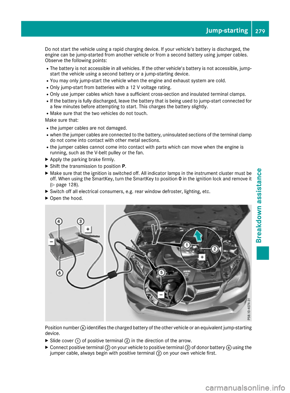
Position number Bidentifies the charged battery of the other vehicle or an equivalent jump-starting
device.
XSlide cover :of positive terminal ;in the direction of the arrow.
XConnect positive terminal ;on your vehicle to positive terminal =of donor battery Busing the
jumper cable, always begin with positive terminal ;on your own vehicle first.
Jump-starting279
Breakdown assistance
Z
Page 282 of 322
XStart the engine of the donor vehicle and run it at idling speed.
XConnect negative terminal?of donor battery Bto ground point Aof your vehicle using the
jumper cable, connecting the jumper cable to battery of other vehicle Bfirst.
XStart the engine.
XBefore disconnecting the jumper cables, let the engine run for several minutes.
XFirst, remove the jumper cables from ground point Aand negative terminal ?, then from pos-
itive clamp ;and positive terminal =. Begin each time at the contacts on your own vehicle first.
XClose cover:of positive clamp ;after removing the jumper cables.
XHave the battery checked at a qualified specialist workshop.
Jump-starting is not considered to be a normal operating condition.
iJumper cables and further information regarding jump-starting can be obtained at any qualified
specialist workshop.
Towing and tow-starting
Important safety notes
GWARNING
Functions relevant to safety are restricted or
no longer available if:
Rthe engine is not running.
Rthe brake system or the power steering is
malfunctioning.
Rthere is a malfunction in the voltage supply or the vehicle's electrical system.
If your vehicle is being towed, much more
force may be necessary to steer or brake.
There is a risk of an accident.
In such cases, use a tow bar. Before towing,
make sure that the steering moves freely.
GWARNING
When towing or tow-starting another vehicle
and its weight is greater than the permissible
gross weight of your vehicle, the:
Rthe towing eye could detach itself
Rthe vehicle/trailer combination could roll-
over.
There is a risk of an accident.
When towing or tow-starting another vehicle,
its weight should not be greater than the per- missible gross weight of your vehicle. Details on the permissible gross vehicle weight
of your vehicle can be found on the vehicle iden-
tification plate (
Ypage 311).
!When COLLISION PREVENTION ASSIST
PLUS, DISTRONIC PLUS or the HOLD function
is activated, the vehicle brakes automatically
in certain situations.
To avoid damage to the vehicle, deactivate
these systems in the following or similar sit-
uations:
Rwhen towing the vehicle
Rin the car wash
!Only secure the tow rope or tow bar at the
towing eyes. Otherwise, the vehicle could be
damaged.
!Do not use the towing eye for recovery, this
could damage the vehicle. If in doubt, recover
the vehicle with a crane.
!When towing, pull away slowly and
smoothly. If the tractive power is too high, the
vehicles could be damaged.
!Do not tow with sling-type equipment. This
could damage the vehicle.
!On vehicles with KEYLESS-GO, use the
SmartKey instead of the Start/Stop button.
Turn the SmartKey to position 2in the ignition
lock and shift the automatic transmission to
N. Then, turn the SmartKey back to 0and
leave it in the ignition lock.
!The vehicle can be towed a maximum of
30 miles (50km). The towing speed of 30 mph
(50 km/h) must not be exceeded.
280Towing and tow-starting
Breakdown assistance
Page 283 of 322
If the vehicle has to be towed more than
30 miles (50km), the entire vehicle must be
raised and transported.
!If you tow or tow-start another vehicle, its
weight must not exceed the maximum per-
missible gross vehicle weight of your vehicle.
It is better to have the vehicle transported than
to have it towed away.
If the vehicle has suffered transmission damage,
have it transported on a transporter or trailer.
The automatic transmission must be in position
N when the vehicle is being towed.
The battery must be connected and charged.
Otherwise, you:
Rcannot turn the SmartKey to position 2in the
ignition lock
Rcannot shift the automatic transmission to
position N
In the event of damage to the electrical sys-
tem
If the battery is defective, the automatic trans-
mission will be locked in position P. To shift the
automatic transmission to position N, you must
provide power to the vehicle's electrical system
in the same way as when jump-starting
(
Ypage 278).
Have the vehicle transported on a transporter or
trailer.
Disarm the automatic locking feature before the
vehicle is towed (
Ypage 79). You could other-
wise be locked out when pushing or towing the
vehicle.
Installing/removing the towing eye
Installing the towing eye
GWARNING
The exhaust tail pipe may be very hot. There is
a risk of burns when removing the rear cover.
Do not touch the exhaust pipe. Take particular
care when removing the rear cover.
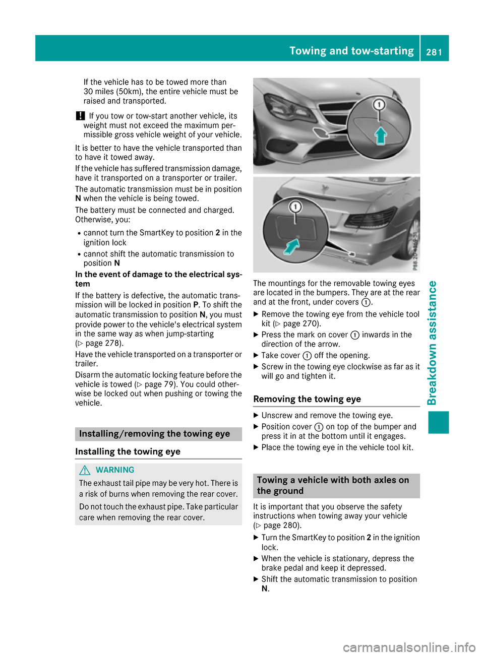
The mountings for the removable towing eyes
are located in the bumpers. They are at the rear
and at the front, under covers :.
XRemove the towing eye from the vehicle tool
kit (Ypage 270).
XPress the mark on cover:inwards in the
direction of the arrow.
XTake cover :off the opening.
XScrew in the towing eye clockwise as far as it
will go and tighten it.
Removing the towing eye
XUnscrew and remove the towing eye.
XPosition cover :on top of the bumper and
press it in at the bottom until it engages.
XPlace the towing eye in the vehicle tool kit.
Towing a vehicle with both axles on
the ground
It is important that you observe the safety
instructions when towing away your vehicle
(
Ypage 280).
XTurn the SmartKey to position 2in the ignition
lock.
XWhen the vehicle is stationary, depress the
brake pedal and keep it depressed.
XShift the automatic transmission to position
N.
Towing and tow-starting281
Breakdown assistance
Z
Page 284 of 322
XReleaseth ebrak epedal .
XReleas eth eparking brake.
In order to signal achang eof direction when
towin gth evehicl ewit hth ehazard warning
lamp sswitched on ,use th ecombination switch
as usual. In this case, only th eindicator lamp s
for th edirection of travel flash. Afte rresetting
th ecombination switch ,th ehazard warning
lamp start sflashin gagain .
Towing the vehicle with the rear axle
raised
!
Vehicles wit h4MATIC mus tno tbe towed
wit heither th efron tor th erear axl eraised, as
doin gso will damag eth etransmission .
!Vehicles withautomatic transmission mus t
no tbe towed wit hth erear axl eraised. The
vehicle/traile rcombination may otherwise
swerve or eve nrol lover.
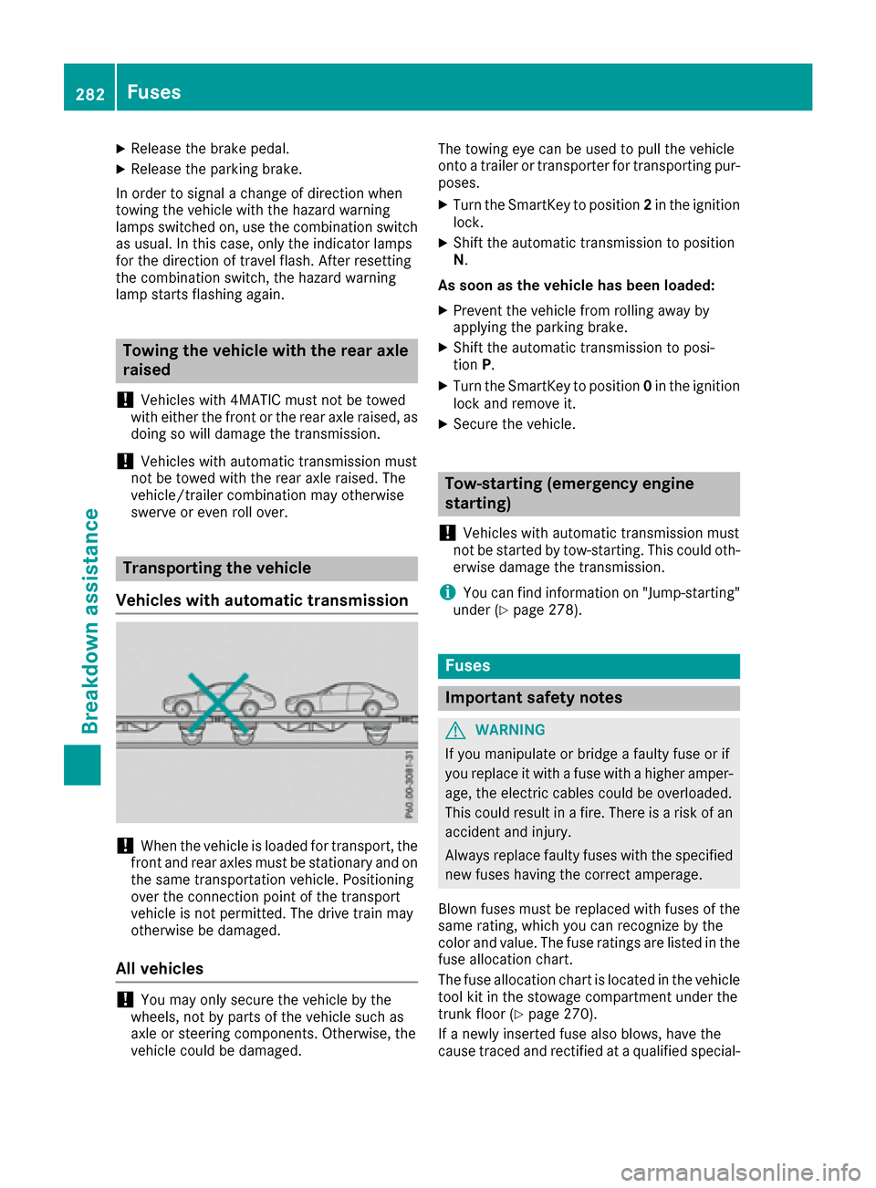
Transporting the vehicle
Vehicles with automatic transmission
!When th evehicl eis loade dfor transport, th e
fron tand rear axles mus tbe stationary and on
th esam etransportation vehicle. Positioning
ove rth econnection poin tof th etranspor t
vehicl eis no tpermitted. The driv etrain may
otherwise be damaged.
All vehicles
!You may only secure th evehicl eby th e
wheels, no tby part sof th evehicl esuc has
axl eor steering components. Otherwise, th e
vehicl ecould be damaged. The towin
geye can be used to pull th evehicl e
onto atrailer or transporte rfor transporting pur-
poses.
XTurn th eSmartKey to position 2in th eignition
lock.
XShift th eautomatic transmission to position
N .
As soon as th evehicle ha sbeen loaded:
XPreven tth evehicl efrom rollin gaway by
applyin gth eparking brake.
XShift th eautomatic transmission to posi-
tion P.
XTurn th eSmartKey to position 0in th eignition
loc kand remove it .
XSecureth evehicle.
Tow-starting (emergency engine
starting)
!
Vehicles wit hautomatic transmission mus t
no tbe started by tow-starting .This could oth-
erwise damag eth etransmission .
iYou can findinformation on "Jump-starting "
under (Ypage 278).
Fuses
Important safety notes
GWARNIN G
If you manipulat eor bridge afault yfus eor if
you replace it wit h afusewit h a higher amper-
age, th eelectric cables could be overloaded.
This could result in afire. There is aris kof an
acciden tand injury.
Always replace fault yfuses wit hth especifie d
ne wfuses having th ecorrec tamperage .
Blown fuses mus tbe replace dwit hfuses of th e
sam erating ,whic hyou can recogniz eby th e
color and value .The fus erating sare listed in th e
fus eallocation chart .
The fus eallocation chart is locate din th evehicl e
tool kit in th estowage compartmen tunder th e
trunk floor (
Ypage 270).
If anewly inserted fus ealso blows ,hav eth e
caus etrace dand rectifie dat aqualified special-
282Fuses
Breakdown assistance
Page 285 of 322
ist workshop, e.g. an authorized Mercedes-Benz
Center.
!Only use fuses that have been approved for
Mercedes-Benz vehicles and which have the
correct fuse rating for the system concerned.
Otherwise, components or systems could be
damaged.
!Make sure that no moisture can enter the
fuse box when the cover is open.
!When closing the cover, make sure that it is
lying correctly on the fuse box. Moisture seep-
ing in or dirt could otherwise impair the oper-
ation of the fuses.
The fuses in your vehicle serve to close down
faulty circuits. If a fuse blows, all the compo-
nents on the circuit and their functions stop
operating.
Before changing a fuse
Pay attention to the important safety notes
(Ypage 282).
XSwitch off the engine.
XSwitch off all electrical consumers.
XSecure the vehicle against rolling away
(Ypage 144).
XRemove the SmartKey from the ignition lock.
or, on vehicles with KEYLESS‑ GO:
XOpen the driver's door.
The on-board electronics now have status 0.
This is the same as the SmartKey having been
removed.
XRemove the Start/Stop button from the igni-
tion lock (Ypage 128).
All indicator lamps in the instrument cluster
must be off.
The fuses are located in various fuse boxes:
RFuse box on the driver's side of the dashboard
RFuse box in the engine compartment on the
left-hand side of the vehicle, when viewed in
the direction of travel
RFuse box in the trunk on the right-hand side of
the vehicle, when viewed in the direction of
travel
Dashboard fuse box
Pay attention to the important safety notes
(Ypage 282).
!Do not use a pointed object such as a screw-
driver to open the cover in the dashboard. You
could damage the dashboard or the cover.
!Make sure that no moisture can enter the
fuse box when the cover is open.
!When closing the cover, make sure that it is
lying correctly on the fuse box. Moisture seep-
ing in or dirt could otherwise impair the oper-
ation of the fuses.
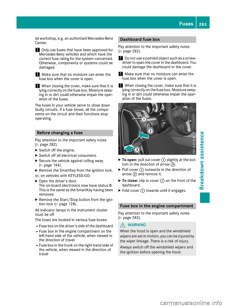
XTo open: pull out cover :slightly at the bot-
tom in the direction of arrow =.
XPull cover:outwards in the direction of
arrow ;and remove it.
XTo close: clip in cover :on the front of the
dashboard.
XFold cover :inwards until it engages.
Fuse box in the engine compartment
Pay attention to the important safety notes
(Ypage 282).
GWARNING
When the hood is open and the windshield
wipers are set in motion, you can be injured by
the wiper linkage. There is a risk of injury.
Always switch off the windshield wipers and
the ignition before opening the hood.
Fuses283
Breakdown assistance
Z
Page 295 of 322
In addition to the warning lamp, a message
appears in the multifunction display. Observe
the information on display messages
(
Ypage 219).
It may take up to ten minutes for a malfunction of the tire pressure monitor to be indicated. A
malfunction will be indicated by the tire pres-
sure warning lamp flashing for approximately
one minute and then remaining lit. When the
malfunction has been rectified, the tire pressure
warning lamp goes out after a few minutes of
driving.
The tire pressure values indicated by the on-
board computer may differ from those meas-
ured at a gas station with a pressure gauge. The
tire pressures shown by the on-board computer
refer to those measured at sea level. At high
altitudes, the tire pressure values indicated by a
pressure gauge are higher than those shown by the on-board computer. In this case, do not
reduce the tire pressures.
The operation of the tire pressure monitor can
be affected by interference from radio transmit-
ting equipment (e.g. radio headphones, two-way
radios) that may be being operated in or near the vehicle.
Checking the tire pressure electroni-
cally
XMake sure that the SmartKey is in position 2
in the ignition lock (Ypage 128).
XPress the =or; button on the steering
wheel to select the Servicemenu.
XPress the9or: button to select
Tire Pressure.
XPress the abutton.
The current tire pressure of each tire is shown
in the multifunction display.
If the vehicle has been parked for over
20 minutes, the Tire pressures will be
displayed after driving a few minutesmessage appears.
After a teach-in process, the tire pressure mon-
itor automatically detects new wheels or new
sensors. As long as a clear allocation of the tire
pressure value to the individual wheels is not
possible, theTire
PressureMonitorActivedisplay message is shown instead of the tire
pressure display. The tire pressures are already
being monitored.
If an emergency spare wheel is mounted, the
system may continue to show the tire pressure of the wheel that has been removed for a few
minutes. If this occurs, note that the value dis-
played for the position where the spare wheel is
mounted is not the same as the current tire
pressure of the emergency spare wheel.
Tire pressure monitor warning mes-
sages
If the tire pressure monitor detects a pressure
loss in one or more tires, a warning message is
shown in the multifunction display. The yellow
tire pressure warning lamp then lights up.
RIf the Correct Tire Pressuremessage
appears in the multifunction display, the tire
pressure in at least one tire is too low. The tire pressure must be corrected when the oppor-
tunity arises.
RIf the Check Tiresmessage appears in the
multifunction display, the tire pressure in one
or more tires has dropped significantly. The
tires must be checked.
RIf the WarningTireMalfunctionmessage
appears in the multifunction display, the tire
pressure in one or more tires is dropping sud-
denly. The tires must be checked.
Observe the instructions and safety notes in the
display messages in the "Tires" section
(
Ypage 219).
If the wheel positions on the vehicle are rotated,
the tire pressures may be displayed for the
wrong positions for a short time. This is rectified after a few minutes of driving, and the tire pres-
sures are displayed for the correct positions.
Restarting the tire pressure monitor
When you restart the tire pressure monitor, all
existing warning messages are deleted and the
warning lamps go out. The monitor uses the cur-
rently set tire pressures as the reference valuesfor monitoring. In most cases, the tire pressure
monitor will automatically detect the new refer-
ence values after you have changed the tire
pressure. However, you can also define refer-
ence values manually as described here. The tire
pressure monitor then monitors the new tire
pressure values.
XSet the tire pressure to the value recommen- ded for the corresponding driving situation on
the Tire and Loading Information placard on
the driver's side B-pillar (
Ypage 288).
Tire pressure293
Wheels and tires
Z
Page 296 of 322
You can find more tire pressure values for
various operating conditions in the tire pres-
sure table inside the fuel filler flap
(
Ypage 288).
XMake sure that the tire pressure is correct on
all four wheels.
XMake sure that the SmartKey is in position2
in the ignition lock.
XPress the =or; button on the steering
wheel to select the Servicemenu.
XPress the9or: button to select
Tire Pressure.
XPress the abutton.
The multifunction display shows the current
tire pressure for the individual tires or the
Tire pressures will be displayed
after driving a few minutesmessage.
XPress the :button.
The UseCurrentPressuresasNewRef‐erenceValuesmessage appears in the mul-
tifunction display.
If you wish to confirm the restart:
XPress the abutton.
The TirePress.MonitorRestartedmes-
sage appears in the multifunction display.
After driving for a few minutes, the system
checks whether the current tire pressures are within the specified range. The new tire pres-
sures are then accepted as reference values
and monitored.
If you wish to cancel the restart:
XPress the %button.
The tire pressure values stored at the last
restart will continue to be monitored.
Loading the vehicle
Instruction labels for tires and loads
GWARNING
Overloaded tires can overheat, causing a
blowout. Overloaded tires can also impair the steering and driving characteristics and lead
to brake failure. There is a risk of accident.
Observe the load rating of the tires. The load
rating must be at least half of the GAWR of
your vehicle. Never overload the tires by
exceeding the maximum load. Two instruction labels on your vehicle show the
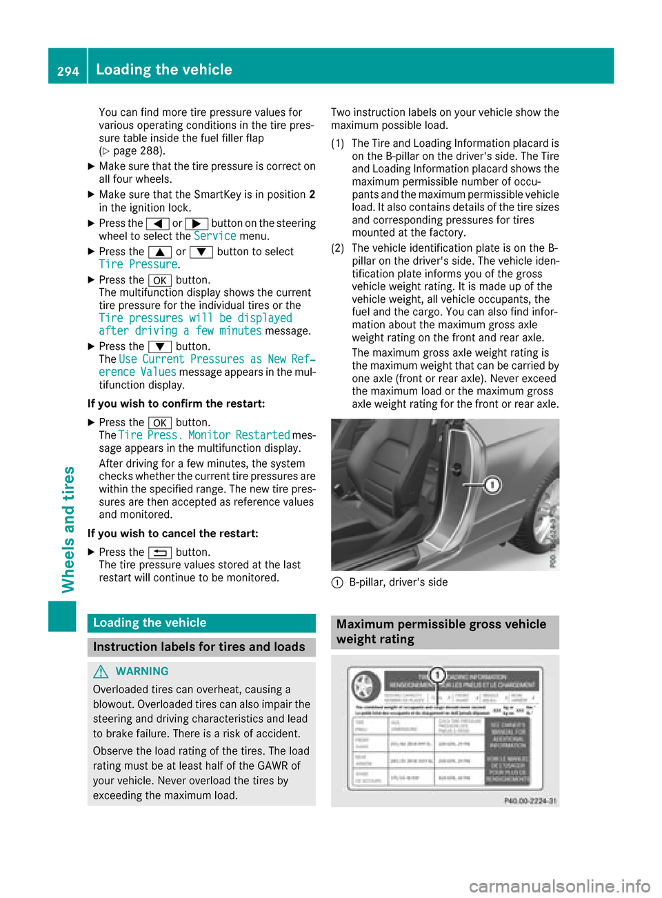
maximum possible load.
(1) The Tire and Loading Information placard is on the B-pillar on the driver's side. The Tire
and Loading Information placard shows the
maximum permissible number of occu-
pants and the maximum permissible vehicle
load. It also contains details of the tire sizes
and corresponding pressures for tires
mounted at the factory.
(2) The vehicle identification plate is on the B- pillar on the driver's side. The vehicle iden-
tification plate informs you of the gross
vehicle weight rating. It is made up of the
vehicle weight, all vehicle occupants, the
fuel and the cargo. You can also find infor-
mation about the maximum gross axle
weight rating on the front and rear axle.
The maximum gross axle weight rating is
the maximum weight that can be carried by
one axle (front or rear axle). Never exceed
the maximum load or the maximum gross
axle weight rating for the front or rear axle.
:B-pillar, driver's side
Maximum permissible gross vehicle
weight rating
294Loading the vehicle
Wheels and tires
Page 306 of 322
Tire-mounting tools should not be used near
the valve. This could damage the electronic
components.
Only have tires changed at a qualified spe-
cialist workshop.
Always observe the instructions and safety
notes in the "Mounting a wheel" section
(
Ypage 304).
The wear patterns on the front and rear tires
differ, depending on the operating conditions.
Rotate the wheels before a clear wear pattern
has formed on the tires. Front tires typically
wear more on the shoulders and the rear tires in the center.
On vehicles that have the same size front and
rear wheels, you can rotate the wheels accord-
ing to the intervals in the tire manufacturer's
warranty book in your vehicle documents. If no
warranty book is available, the tires should be
rotated every 3,000 to 6,000 miles (5,000 to
10,000 km). Depending on tire wear, this may
be required earlier. Do not change the direction
of wheel rotation.
Clean the contact surfaces of the wheel and the
brake disc thoroughly every time a wheel is rota-
ted. Check the tire pressure and reactivate the
tire pressure monitor if necessary (
Ypage 293).
Direction of rotation
Tires with a specified direction of rotation have
additional benefits, e.g. if there is a risk of hydro-
planing. These advantages can only be gained if
the tires are installed corresponding to the
direction of rotation.
An arrow on the sidewall of the tire indicates its
correct direction of rotation.
Storing wheels
Store wheels that are not being used in a cool,
dry and preferably dark place. Protect the tires
from oil, grease, gasoline and diesel.
Mounting a wheel
Preparing the vehicle
XStop the vehicle on solid, non-slippery and
level ground.
XApply the parking brake.
XBring the front wheels into the straight-ahead
position.
XShift the transmission to position P.
XSwitch off the engine.
XRemove the SmartKey from the ignition lock.
or, on vehicles with KEYLESS‑ GO:
XOpen the driver's door.
The on-board electronics now have status 0.
This is the same as the SmartKey having been
removed.
XRemove the Start/Stop button from the igni-
tion lock (Ypage 128).
XIf included in the vehicle equipment, remove
the tire-change tool kit from the vehicle
(
Ypage 270).
XSafeguard the vehicle against rolling away.
Securing the vehicle to prevent it from
rolling away
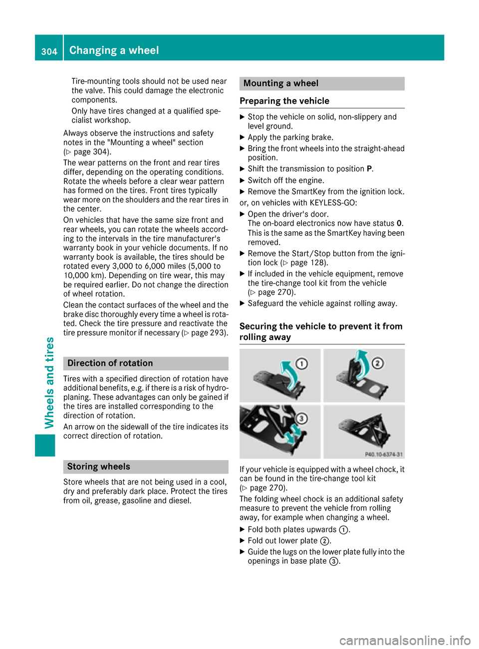
If your vehicle is equipped with a wheel chock, it
can be found in the tire-change tool kit
(
Ypage 270).
The folding wheel chock is an additional safety
measure to prevent the vehicle from rolling
away, for example when changing a wheel.
XFold both plates upwards :.
XFold out lower plate;.
XGuide the lugs on the lower plate fully into the
openings in base plate =.
304Changing a wheel
Wheels and tires