tow bar MERCEDES-BENZ E-CLASS ESTATE 2012 Owners Manual
[x] Cancel search | Manufacturer: MERCEDES-BENZ, Model Year: 2012, Model line: E-CLASS ESTATE, Model: MERCEDES-BENZ E-CLASS ESTATE 2012Pages: 457, PDF Size: 11.62 MB
Page 68 of 457
Fitting side head restraints
X
Slide head restraint ;upwards and posi-
tio nitu pright.
X Slide side head restraints Bfrom the front
to the centre of both head restraint bars
until they engage.
The right -and left-hand lock verification
indicators =must be folded in. The red
surfaces are no longe rvisible.
X Make sure that side head restraint Bis
engaged in both head restraint bars.
X Slide head restraint ;downwards
(Y page 110) until it rests on the upper
edge of side head restraints B.
X Guide the seat belt through seat belt guide
A on the door side on side head restraint
B.
X Secure the child (Y page 62).
Removing the side head restraints
X Take the seat belt out of seat belt guide
A.
X Move head restraint ;upwards.
X Press left or right release button ?and pull
side head restraint Bforward to remove
it.
The left and right lock verification indica-
tors :fold out briefly.
X Adjust head restraint ;(Ypage 110).
i Should a side head restraint be required
for the second integrated child seat, this
can be ordered at any Mercedes-Benz
Service Centre.
Storing the ICS padded play table and
the side head restraint G
WARNING
Secure the ICS padded play table and the side
head restraints in the vehicle as specified;
otherwise, they may com eloose. In the event
of an accident, sudden braking or abrupt
change in direction, they could injure vehicle
occupants or cause damage to the vehicle. When you are not using the ICS padded play
table and the side head restraints, store these
in a suitable place, such as the boot.
For example, on vehicles with TIREFIT, you
can store the side head restraints in the stow-
age compartment under the boot/luggage
compartment floor (Y page 325)/
(Y page 325).
Suitable positioning of the child
restraint systems X
To install a child restraint system on
the front-passenger seat: move the front-
passenger seat to the rearmost and lowest
position and the belt outlet height to the
lowest position.
Key to the letters used in the following table:
XS eat which is unsuitable for children in
this weight category.
US uitable for child restraint systems in the
"Universal" category that are approved
for use in this weigh tcategory.
LS uitable for child restraint systems as rec-
ommended, see the following table of
"Recommended child restraint systems"
(Y page 67).
Front-passenger seat Weight cat-
egories Front-
passenger
airbag is
not disa-
bled: Front-
passenger
front air-
bag is disa-
bled.
Categor
y0:
up to 10 kg X L
Category
0+: up to
13 kg
X L
Category I:
9 to 18 kg
L LChildren in the vehicle
65Safety Z
Page 214 of 457
X
To store: press AMG button ;until you
hea ratone.
X To call up: press AMG button ;.
The stored suspensio ntuning and drive
program are selected.
X To display: briefly press AMG button ;.
Your selection appears in the multifunction
display. 4MATIC (permanent all-wheel drive)
G
WARNING
4MATIC canno treduce the risk of an accident
if you drive too fast.
If a drive wheel spins due to insufficient grip:
R only depress the accelerator pedal as far as
necessary when pulling away.
R accelerate less when driving.
R adapt your driving style to suit road and
traffic conditions.
! Never tow the vehicle with one axle
raised. This may damage the transfer case.
Damage of this sort is not covered by the
Mercedes-Benz implied warranty. All
wheels must remain either on the ground
or be fully raised. Observe the instructions
for towing the vehicle with all wheels in full
contact with the ground.
i In wintry driving conditions, the maximum
effect of 4MATIC can only be achieved if
you use winter tyres (M+ Styres), with snow
chains if necessary.
4MATIC ensures that all four wheels are per-
manently driven. Together with ESP ®
, it
improves the traction of your vehicle when-
eve radrive wheel spins due to insufficient
grip. PARKTRONIC
Important safety notes G
WARNING
PARKTRONIC is only an aid and may not
detec tall obstacles. It is not a substitute for
attentive driving.
You are always responsible for safety and
must continue to pay attention to your imme-
diate surroundings when parking and
manoeuvring. You could otherwise endanger
yourself and others. G
WARNING
Make sure that no persons or animals are in
the manoeuvring range. Otherwise, they
could be injured.
PARKTRONIC is an electronic parking aid with
ultrasonic sensors .Itindicates visually and
audibly the distance between your vehicle
and an object.
PARKTRONIC is activated automatically if
you:
R switch on the ignition
R shift to position D,Ror Non vehicles with
automatic transmission
R release the parking brake
PARKTRONIC is deactivated at speeds above
18 km/h. It is reactivated at lower speeds.
PARKTRONIC monitors the area around your
vehicle using si xsensors in the fron tbumper
and four sensors in the rear bumper.
Range of the sensors General notes
!
When parking, pay particular attention to
objects above or below the sensors, such
as flower pots or trailer drawbars. PARK-
TRONIC does no tdetec tsuch objects when
they are in the immediat evicinity of the
vehicle. You could damage the vehicle or
the objects. Driving systems
211Driving and parking Z
Page 219 of 457
G
WARNING
Make sure that no persons or animals are in
the manoeuvring range. Otherwise, they
could be injured.
! If unavoidable, you should drive over
obstacles such as kerbs slowly and not at
a sharp angle .Otherwise, you may damage
the wheels or tyres.
Parking Guidance is an electroni cparking aid
with ultrasound. Ultrasound is used to meas-
ure the road on both sides of the vehicle .A
suitable parking space is indicated by the
parking symbol. You receive steering instruc-
tions when parking. You may also use PARK-
TRONIC (Y page 211).
When PARKTRONIC is deactivated, Parking
Guidance is also unavailable.
Use Parking Guidance for parking spaces:
R that are parallel to the direction of travel
R that are on straight roads, not bends
R that are on the same level as the road, i.e.
not on the pavement, for example. Parking
Guidance may not detect flat kerbs
Parking tips:
R on narrow roads, drive as closely as possi-
ble past the parking space.
R parking spaces that are littered, overgrown
or partially occupied by trailer drawbars
might be identified incorrectly or not at all.
R snowfall or heavy rain may lead to a parking
space being measured inaccurately.
R pay attention to the PARKTRONIC
(Y page 213) warning messages during the
parking procedure.
R when transporting a load which protrudes
from your vehicle, you must not use Parking
Guidance.
R never use Parking Guidance with snow
chains or an emergency spare wheel fitted. R
make sure that the tyre pressures are
always correct.T his hasadirec teffect on
the steering instructions.
R the way you rvehicle is positioned in the
parking space after parkin gis dependent
on various factors. These include the posi-
tion and shape of the vehicles parked in
front and behind it and the conditions of the
location. In some cases, Parking Guidance
may guide you too far or not far enough into
a parking space. In some cases, it may also
lead you across or onto the kerb. If neces-
sary, cancel the parking procedure with
Parking Guidance.
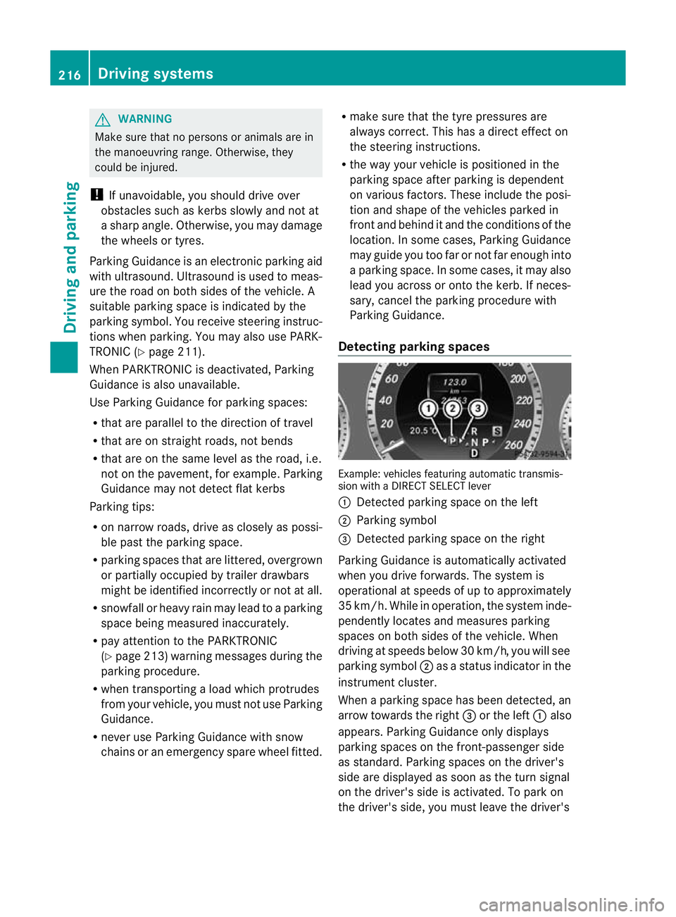
Detecting parking spaces Example: vehicles featuring automatic transmis-
sion with a DIRECT SELECT lever
:
Detected parking space on the left
; Parking symbol
= Detected parking space on the right
Parking Guidance is automatically activated
when you drive forwards. The system is
operational at speeds of up to approximately
35 km/h. While in operation, the system inde-
pendently locates and measures parking
spaces on both sides of the vehicle. When
driving at speeds below 30 km/h, you will see
parking symbol ;as a status indicator in the
instrument cluster.
When a parking space has been detected, an
arrow towards the right =or the left :also
appears. Parking Guidance only displays
parking spaces on the front-passenger side
as standard. Parking spaces on the driver's
side are displayed as soon as the turn signal
on the driver's side is activated. To park on
the driver's side, you must leave the driver's 216
Driving systemsDriving and parking
Page 222 of 457
could otherwise endanger yoursel
fand oth-
ers. G
WARNING
Unde rthe following circumstances, the
reversing camera will not function, or will
function in a limited manner:
R if the tailgate is open
R in heavy rain, snow or fog
R at night or in very dark places
R if the camera is exposed to very bright light
R if the area is lit by fluorescent light or LED
lighting (the display may flicker)
R if there is a sudden change in temperature,
e.g. when driving into a heated garage in
winter
R if the camera lens is dirty or obstructed
R if the rear of your vehicle is damaged. In this
event, have the camera position and setting
checked at a qualified specialist workshop.
Mercedes-Ben zrecommends that you use
a Mercedes-Benz Service Centre for this
purpose.
Do not use the reversing camera in these
types of situation .You could otherwise injure
others or damage objects and your vehicle
while you are parking.
The area behind the vehicle is displayed as a
mirror image, as in the rear-view mirror.
Activating the reversing camera X
Make sure that the key is in position 2in
the ignition lock.
X Make sure that the "Reversing camera"
function is selected in COMAND APS (see
the separate operating instructions for
COMAND APS).
X Engage reverse gear.
The area behind the vehicle is shown with
guide lines in the COMAND display. Guide lines in the COMAND display G
WARNING
Using the reversing camera can be dangerous
if you are colour blind or your ability to distin-
guish colours is impaired.
Only use the reversing camera if you can see
and distinguish between all the coloured
guide lines that are displayed by the reversing
camera in the COMAND display. G
WARNING
Please note that objects not at ground level
may appear to be further away than they
actually are. These include:
R the bumper of a vehicle that is parked
behind your vehicle
R a trailer drawbar
R the ball coupling of a trailer tow hitch
R the tail-end of a lorry
R slanted posts
The lines are only guides, not accurate meas-
urements of the distance to an obstacle.
Therefore, you should never pass the red line
when approaching an obstacle. You could oth-
erwise cause an accident and injure yourself
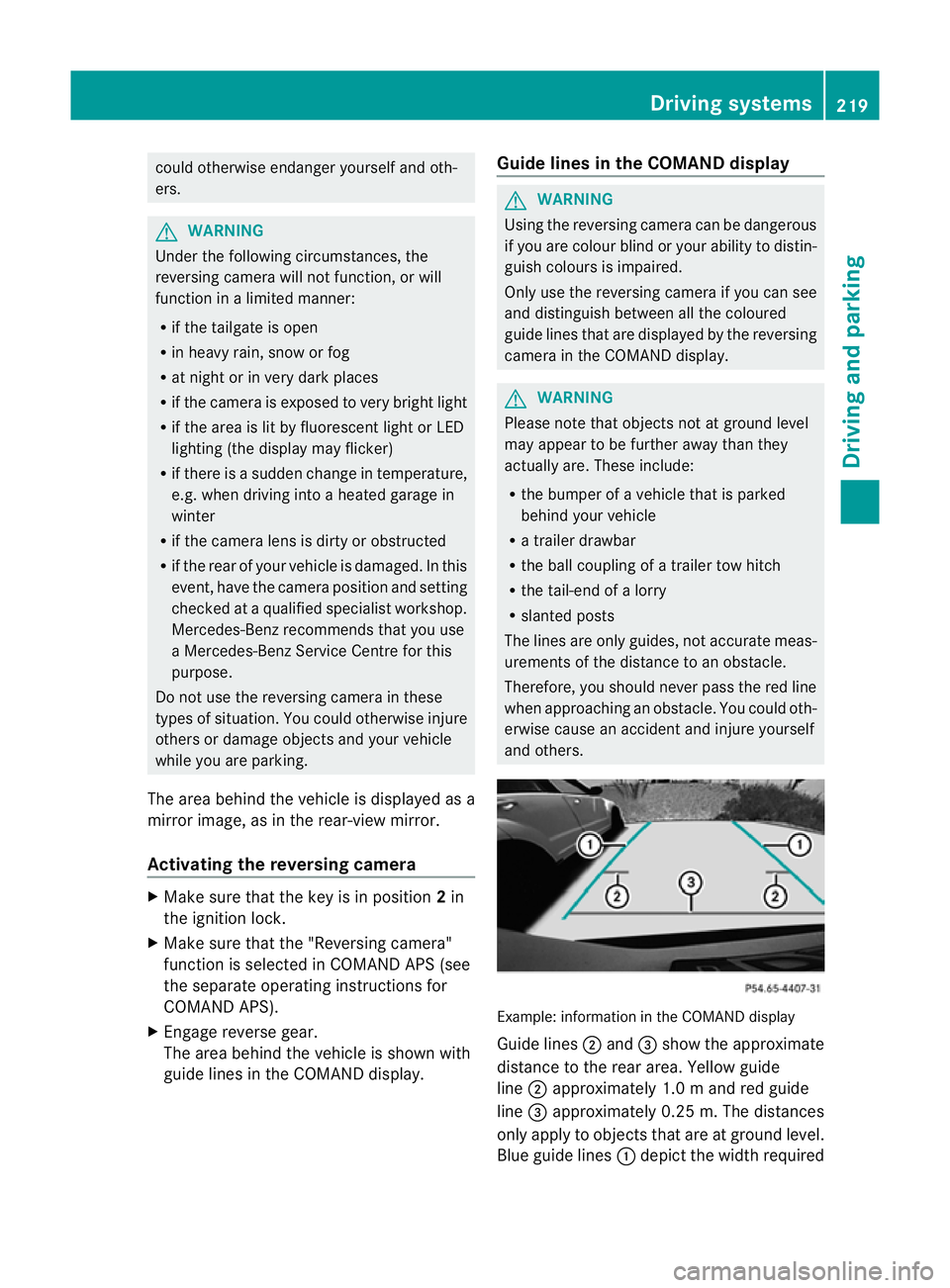
and others. Example: information in the COMAND display
Guide lines
;and =show the approximate
distance to the rear area. Yellow guide
line ;approximately 1.0 mand red guide
line =approximately 0.25 m. The distances
only apply to objects that are at ground level.
Blue guide lines :depict the width required Driving systems
219Driving and parking Z
Page 238 of 457
Never use the brake pedal as a footrest. Do
not simultaneously depress both the brake
pedal and the accelerator pedal while driving. G
WARNING
You could lose control of the vehicle/trailer
combination if it begins to swerve. The vehi-
cle/trailer combination could even overturn.
There is a risk of an accident.
On no account should you attempt to
straighten out the vehicle/trailer combina-
tion by increasing speed. Decrease your
speed and do not countersteer. Brake if nec-
essary. G
WARNING
If you exceed the permissible noseweight
while carrying a load, the carrier system could
detach from the vehicle and fall on the road.
There is a risk of an accident and injury.
Always maintain the permissible noseweight
when carrying loads. G
WARNING
If the ball coupling is not correctly engaged, it
could detach while driving and fall on the road.
There is a risk of an accident and injury.
Engage the ball coupling as described. G
WARNING
If the ball coupling is not correctly engaged,
the trailer can detach. There is a risk of an
accident.
Always engage the ball coupling as described.
! Depressing the brake pedal constantly
results in excessive and premature wearto
the brake pads.
You can use carrier systems, e.g .bicycle
racks or load-bearing implements, on the ball
coupling. The maximum noseweight of
75 kg applies when using carrier systems on
the ball coupling.
When reversing the vehicle towards the
trailer, make sure there is nobody between
the trailer and the vehicle. Couple and uncouple the trailer carefully. If
you do not couple the trailer to the towing
vehicle correctly, the trailer could become
detached.
Make sure that the followin gvalues are not
exceeded:
R the permissible trailer drawbar noseweight
R the permissible trailer load
R the permissible rear axle load of the towing
vehicle
R the maximum permissible gross vehicle
weigh tofboth the towing vehicle and the
trailer
You will find the applicable permissible val-
ues, which must not be exceeded, in the vehi-
cle documents.
You will find the values approved by the man-
ufacturer on the vehicle identification plates
and those for the towing vehicle in the "Tech-
nical data" section (Y page 448).
When towing a trailer, your vehicle's handling
characteristics will be different in comparison
to when driving without a trailer.
The vehicle/trailer combination:
R is heavier
R is restricted in its acceleration and gradi-
ent-climbing capability
R has an increased braking distance
R is affected more by strong crosswinds
R demands more sensitive steering
R has a larger turning circle
This could impair the handling characteris-
tics. Adapt your style of driving accordingly.
Maintain a safe distance. Drive carefully.
When towing a trailer, always adjust your
speed to the current road and weather con-
ditions. Do not exceed the maximum permis-
sible speed for your vehicle/trailer combina-
tion. Towing
atrailer
235Driving an d parking Z
Page 239 of 457
Notes on towing
atrailer
General notes !
Use a drawbar noseweigh tas close as
possible to the maximum permissible nose-
weight. Do not use a noseweight of less
than 50kg, otherwise the trailer may come
loose.
Note that the payload and the rear axle load
are reduced by the actual payload.
i When towing a trailer, set the tyre pres-
sure on the rear axle of the towing vehicle
for a maximum load; see the tyre pressure
table in the fuel filler flap (Y page 383).
You will find installation dimensions and loads
in the "Technical data" section
(Y page 447).
The maximum noseweight of the trailer draw-
bar on the ball coupling is 84 kg. The actual
noseweight may however not be higher than
the value which is given on the trailer tow
hitch or trailer identification plates. The low-
est weight applies.
Missing values for the E300 model were not
available at the time of going to print.
Please note that whe ntowing a trailer, PARK-
TRONIC (Y page 211), Parking Guidance
(Y page 215) and Blind Spot Assist
(Y page 225) are only available with limita-
tions, or not at all.
i On vehicles without level control, the
height of the ball coupling will alter accord-
ing to the load placed on the vehicle. If nec-
essary, use a trailer with a height-adjusta-
ble drawbar.
Driving tips i
Observe the notes on ESP ®
trailer stabi-
lisation (Y page 75).
The maximum permissible speed for vehicle/
trailer combinations depends on the type of
trailer. Before beginning the journey, check
the trailer's documents to see what the max-
imum permitted speed is. Observe the legally prescribed maximum speed in the relevant
country.
For certain Mercedes-Benz vehicles, the max-
imum permissible rear axle load is increased
when towing a trailer. Refer to the "Technical
data" section to find out whether this applies
to your vehicle. If you utilise any of the added
maximum rear axle load when towing a trailer,
the vehicle/trailer combination may not
exceed a maximum speed of 100 km/h for
reasons concerning the operating permit.
This also applies in countries in which the
permissible maximum speed for vehicle/
trailer combinations is above 100 km/h.
When towing a trailer, your vehicle's handling
characteristics will be different in comparison
to when driving without a trailer and it will
consume more fuel.
Change into a lower gear in good time on long
and steep downhill gradients.
On long and steep downhill gradients, espe-
cially if the vehicle is laden or towing a trailer,
you must select shift range
1,2or 3.
i This also applies if you have activated
cruise control, SPEEDTRONIC or DIS-
TRONIC PLUS.
This will use the braking effect of the engine,
so less braking will be required to prevent the
vehicle from gaining speed. This relieves the
load on the brake system and prevents the
brakes from overheating and wearing too
quickly. If you need additional braking,
depress the brake pedal repeatedly rather
than continuously.
Driving tips If the trailer swings from side to side:
X
Do not accelerate.
X Do not countersteer.
X Brake if necessary. 236
Towing
atrailerDriving an d parking
Page 241 of 457
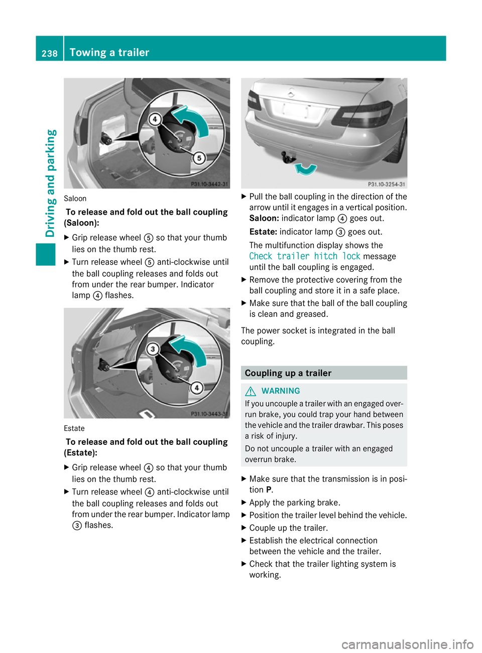
Saloon
To release and fol dout the ball coupling
(Saloon):
X Grip release wheel Aso that you rthumb
lies on the thumb rest.
X Turn release wheel Aanti-clockwise until
the ball coupling releases and folds out
from under the rear bumper. Indicator
lamp ?flashes. Estate
To release and fold out the ball coupling
(Estate):
X Grip release wheel ?so that your thumb
lies on the thumb rest.
X Turn release wheel ?anti-clockwise until
the ball coupling releases and folds out
from under the rear bumper. Indicator lamp
= flashes. X
Pull the ball coupling in the direction of the
arrow until it engages in a vertical position.
Saloon: indicator lamp ?goes out.
Estate: indicator lamp =goes out.
The multifunction display shows the
Check trailer hitch lock message
until the ball coupling is engaged.
X Remove the protective covering from the
ball coupling and store it in a safe place.
X Make sure that the ball of the ball coupling
is clean and greased.
The power socket is integrated in the ball
coupling. Coupling up a trailer
G
WARNING
If you uncouple a trailer with an engaged over-
run brake, you could trap your hand between
the vehicle and the trailer drawbar. This poses
a risk of injury.
Do not uncouple a trailer with an engaged
overrun brake.
X Make sure that the transmission is in posi-
tion P.
X Apply the parking brake.
X Position the trailer level behind the vehicle.
X Couple up the trailer.
X Establish the electrical connection
between the vehicle and the trailer.
X Check that the trailer lighting system is
working. 238
Towing
atrailerDriving an d parking
Page 242 of 457
Uncoupling
atrailer G
WARNING
If you uncouple a trailer with an engaged over-
ru nb rake, you could trap yourh and between
the vehicle and the trailer drawbar .This poses
a risk of injury.
Do not uncouple a trailer with an engaged
overrun brake. G
WARNING
Vehicles with level control:
If you disconnectt he trailer cable, the vehicle
is lowered. This can cause you or others to
become trapped between the vehicle body
and tyres, or underneath the vehicle. This
poses a risk of injury.
Make sure that no-one is in the immediate
vicinity of the wheel arch or underneath the
vehicle when disconnecting the trailer cable.
! Do not disconnect a trailer with an
engaged overrun brake. Otherwise, your
vehicle could be damaged by the rebound-
ing of the overrun brake.
X Make sure that the transmission is in posi-
tion P.
X Apply the parking brake.
X Secure the trailer against rolling away.
X Remove the trailer cable and decouple the
trailer. Folding in the ball coupling
G
WARNING
If you release the ball coupling or it does not
engage correctly when folding in, it will swing
out. Within pivoting range of the ball coupling,
there is an increased risk of an accident and
injury.
Only release the ball coupling if the pivoting
range is unobstructed. Always make sure that
the ball coupling engages when folding in. X
Place the protective covering on the ball
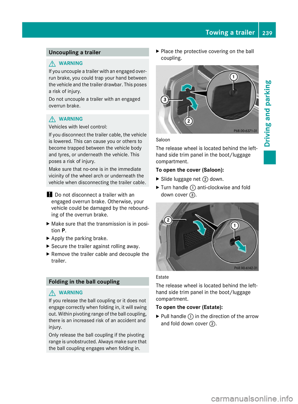
coupling. Saloon
The release wheel is located behind the left-
hand side trim panel in the boot/luggage
compartment.
To open the cover (Saloon):
X
Slide luggage net ;down.
X Turn handle :anti-clockwise and fold
down cover =. Estate
The release wheel is located behind the left-
hand side trim panel in the boot/luggage
compartment.
To open the cover (Estate):
X
Pull handle :in the direction of the arrow
and fold down cover ;. Towing
atrailer
239Driving an d parking Z
Page 343 of 457
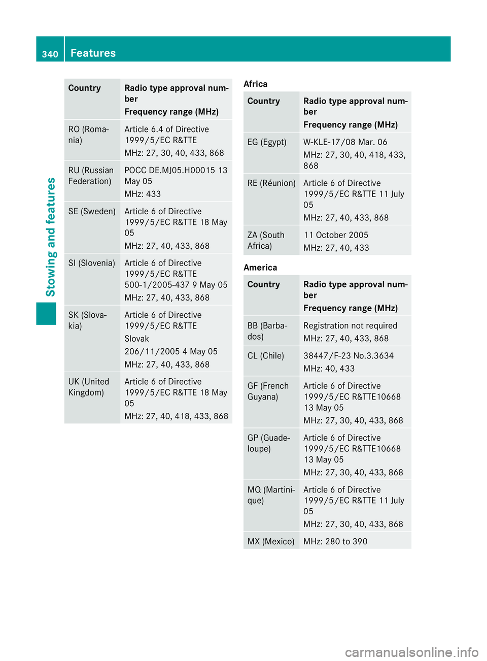
Country Radio type approval num-
ber
Frequency range (MHz)
RO (Roma-
nia) Article 6.4 of Directive
1999/5/EC R&TTE
MHz: 27, 30, 40
,433, 868 RU (Russian
Federation) POCC DE.MJ05.H00015 13
May 05
MHz: 433
SE (Sweden) Article 6 of Directive
1999/5/EC R&TTE 18 May
05
MHz: 27, 40, 433, 868
SI (Slovenia) Article 6 of Directive
1999/5/EC R&TTE
500-1/2005-437 9 May 05
MHz: 27, 40, 433, 868
SK (Slova-
kia) Article 6 of Directive
1999/5/EC R&TTE
Slovak
206/11/2005 4 May 05
MHz: 27, 40, 433, 868
UK (United
Kingdom) Article 6 of Directive
1999/5/EC R&TTE 18 May
05
MHz: 27, 40, 418, 433, 868 Africa
Country Radio type approval num-
ber
Frequency range (MHz)
EG (Egypt) W-KLE-17/08 Mar. 06
MHz: 27, 30, 40, 418, 433,
868
RE (Réunion) Article 6 of Directive
1999/5/EC R&TTE 11 July
05
MHz: 27, 40, 433, 868
ZA (South
Africa) 11 October 2005
MHz: 27, 40, 433
America
Country Radio type approval num-
ber
Frequency range (MHz)
BB (Barba-
dos) Registration not required
MHz: 27, 40, 433, 868
CL (Chile) 38447/F-23 No.3.3634
MHz: 40, 433
GF (French
Guyana) Article 6 of Directive
1999/5/EC R&TTE10668
13 May 05
MHz: 27, 30, 40, 433, 868
GP (Guade-
loupe) Article 6 of Directive
1999/5/EC R&TTE10668
13 May 05
MHz: 27, 30, 40, 433, 868
MQ (Martini-
que) Article 6 of Directive
1999/5/EC R&TTE 11 July
05
MHz: 27, 30, 40, 433, 868
MX (Mexico) MHz: 280 to 390340
FeaturesStowing and features
Page 366 of 457
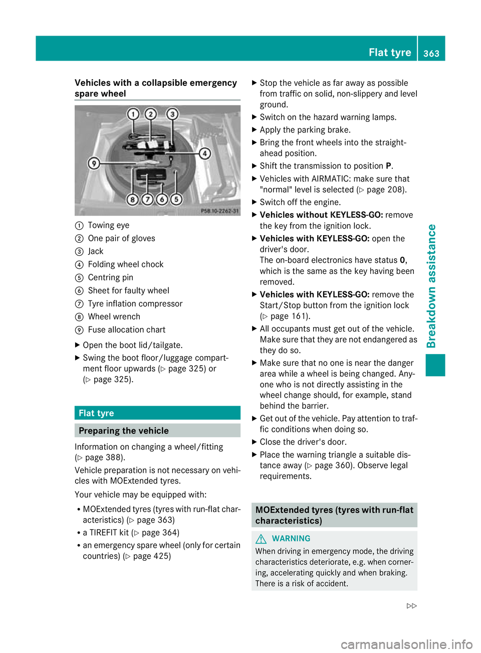
Vehicles with
acollapsible emergency
spare wheel :
Towing eye
; One pair of gloves
= Jack
? Folding wheel chock
A Centring pin
B Sheet for faulty wheel
C Tyre inflatio ncompressor
D Wheel wrench
E Fuse allocation chart
X Open the boot lid/tailgate.
X Swing the boot floor/luggage compart-
ment floor upwards (Y page 325) or
(Y page 325). Flat tyre
Preparing the vehicle
Information on changing a wheel/fitting
(Y page 388).
Vehicle preparation is not necessary on vehi-
cles with MOExtended tyres.
Your vehicle may be equipped with:
R MOExtended tyres (tyres with run-flat char-
acteristics) (Y page 363)
R a TIREFIT kit (Y page 364)
R an emergency spare wheel (only for certain
countries) (Y page 425) X
Stop the vehicle as far away as possible
from traffic on solid, non-slippery and level
ground.
X Switch on the hazard warning lamps.
X Apply the parking brake.
X Bring the front wheels into the straight-
ahead position.
X Shift the transmission to position P.
X Vehicles with AIRMATIC: make sure that
"normal" level is selected (Y page 208).
X Switch off the engine.
X Vehicles without KEYLESS-GO: remove
the key from the ignition lock.
X Vehicles with KEYLESS-GO: open the
driver's door.
The on-board electronics have status 0,
which is the same as the key having been
removed.
X Vehicles with KEYLESS-GO: remove the
Start/Stop button from the ignition lock
(Y page 161).
X All occupants must get out of the vehicle.
Make sure that they are not endangered as
they do so.
X Make sure that no one is near the danger
area while a wheel is being changed. Any-
one who is not directly assisting in the
wheel change should, for example, stand
behind the barrier.
X Get out of the vehicle. Pay attention to traf-
fic conditions when doing so.
X Close the driver's door.
X Place the warning triangle a suitable dis-
tance away (Y page 360). Observe legal
requirements. MOExtended tyres (tyres with run-flat
characteristics)
G
WARNING
When driving in emergency mode, the driving
characteristics deteriorate, e.g. when corner-
ing, accelerating quickly and when braking.
There is a risk of accident. Flat tyre
363Breakdown assistance
Z