clock MERCEDES-BENZ E-CLASS ESTATE 2015 User Guide
[x] Cancel search | Manufacturer: MERCEDES-BENZ, Model Year: 2015, Model line: E-CLASS ESTATE, Model: MERCEDES-BENZ E-CLASS ESTATE 2015Pages: 497, PDF Size: 16.23 MB
Page 276 of 497
X
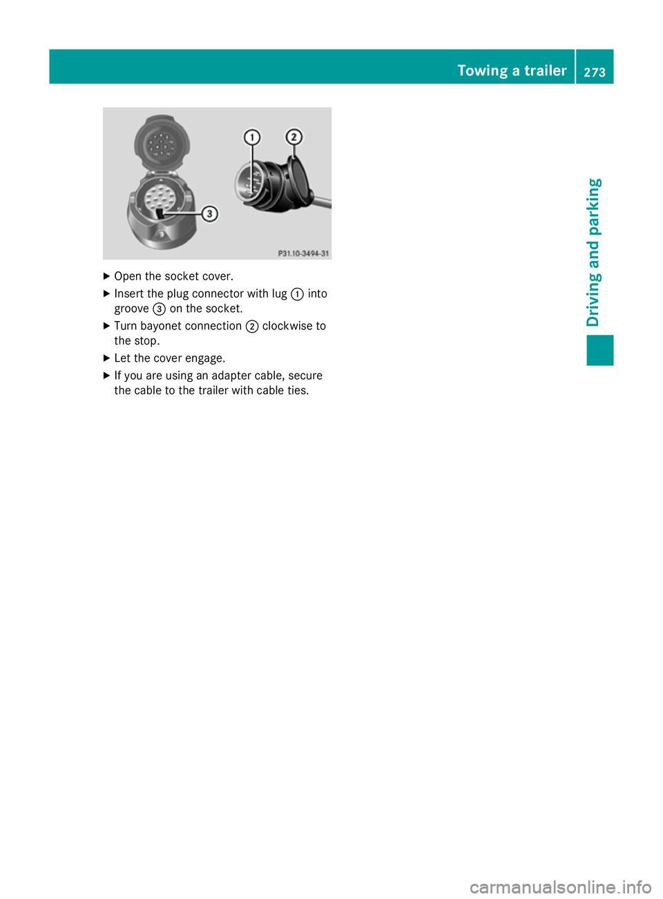
Open the socket cover.
X Insert the plug connector with lug :into
groove =on the socket.
X Turn bayonet connection ;clockwise to
the stop.
X Let the cover engage.
X If you are using an adapter cable, secure
the cable to the trailer with cable ties. Towing
atrailer
273Driving and parking Z
Page 346 of 497
Stowage compartments
Important safety notes G
WARNING
If objectsint he passenger compartmen tare
stowed incorrectly, they can slide or be
thrown around and hit vehicle occupants.
There is arisk of injury, particularly in the
event of sudden braking or asudden change
in direction.
R Always stow objectssot hat they cannot be
thrown around in such situations.
R Always make sure that objectsdon ot pro-
trude from stowage spaces, luggage nets or stowage nets.
R Close the lockable stowage spaces while
driving.
R Always stow and secure heavy, hard, poin-
ted, sharp-edged, fragile or bulky objectsin
the boot/luggage compartment.
Observe the loading guidelines (Y page 342).
Glove compartment X
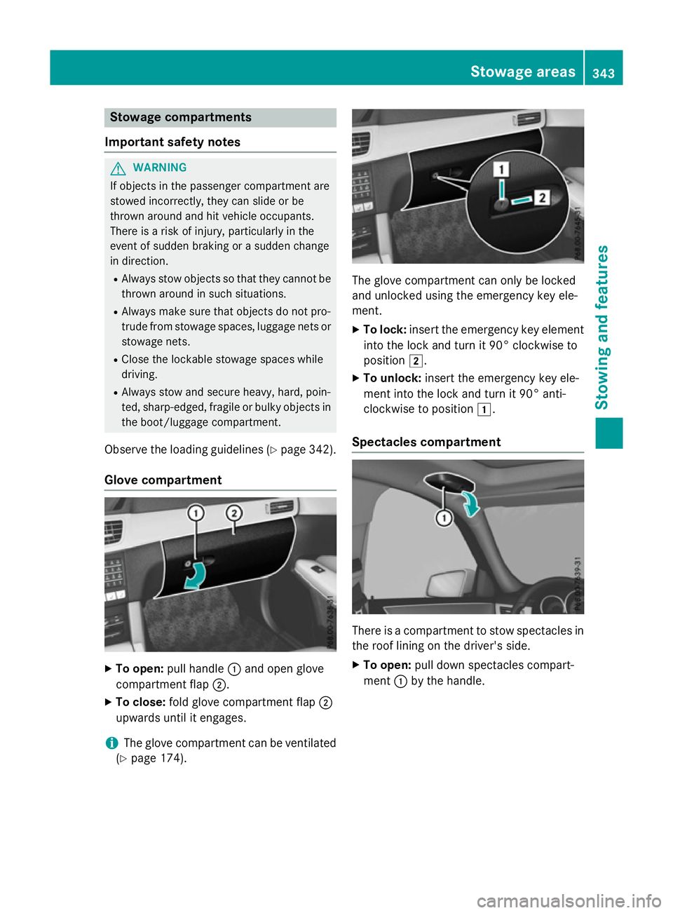
To open: pull handle :and open glove
compartmen tflap ;.
X To close: fold glove compartmen tflap ;
upwards until it engages.
i The glove compartmen
tcan be ventilated
(Y page 174). The glove compartmen
tcan only be locked
and unlocked using the emergency key ele-
ment.
X To lock: insert the emergency key element
into the lock and turn it 90° clockwise to
position 2.
X To unlock: insert the emergency key ele-
ment into the lock and turn it 90° anti-
clockwise to position 1.
Spectacles compartment There is
acompartmen ttostow spectacles in
the roof lining on the driver's side.
X To open: pull down spectacles compart-
ment :by the handle. Stowage areas
343Stowing and features Z
Page 358 of 497
Removin
gand fitting X
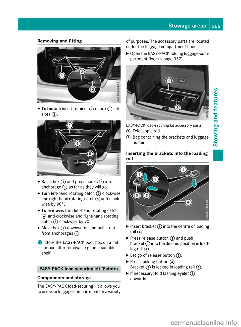
To install: insert retainer ;of box :into
slots =. X
Raise box :and press hooks Ainto
anchorage ?as far as they will go.
X Turn left-hand rotating catch Bclockwise
and right-hand rotating catch Banti-clock-
wise by 90°.
X To remove: turn left-hand rotating catch
B anti-clockwise and right-hand rotating
catch Bclockwise by 90°.
X Move box :downwards and pull it out
from anchorages ?.
i Store the EASY-PAC
Kbootb ox on aflat
surface afte rremoval ,e.g. on asuitable
shelf. EASY-PACK load-securing kit (Estate)
Components and storage The EASY-PAC
Kload-s ecuring kit allows you
to us eyourlug gage compartment for avariety of purposes
.The accessory parts are located
under the luggage compartment floor.
X Ope nthe EASY-PAC Kfolding luggage-com-
partment floor (Y page 357). EASY-PAC
Kload-securing kit accessory parts
: Telescopi crod
; Bag containing the brackets and luggage
holder
Inserting the brackets into the loading
rail X
Insert bracket :into the centre of loading
rail ?.
X Press release button ;and push
bracket :into the desire dposition in load-
ing rail ?.
X Let go of release button ;.
X Press locking button =.
Bracket :is locked in loading rail ?.
X If necessary ,foldl ashing eyelet A
upwards. Stowage areas
355Stowingand features Z
Page 385 of 497
G
WARNING
If engine oil comes into contact with hot com- ponents in the engine compartment, it may
ignite. There is arisk of fire and injury.
Make sure that engine oil does not spil lout
over the filler neck. Allow the engine to cool
downa nd thoroughly clea nthe components
that have come into contact with engine oil
before you start the engine. H
Environmental note
When topping up the oil,t ake care not to spill
any. If oil enters the soil or waterways, it is
harmfu ltothe environment.
! Only use engine oilsa
nd oil filters that
have been approved for vehicles with aser-
vice system. You can obtai nalistoft he
engine oilsa nd oil filters tested and
approved in accordance with the
Mercedes-Benz Specifications for Service
Products at any Mercedes-Benz Service
Centre.
Damag etothe engine or exhaust system is
caused by the following:
R using engine oilsa nd oil filters that have
not been specifically approved for the
service system
R changing the engine oil and oil filter after
missing the change interval required by
the service system
R using engine oil additives
! Do not add too much oil.T
opping up with
too much engine oil can result in damage to
the engine or to the catalytic converter.
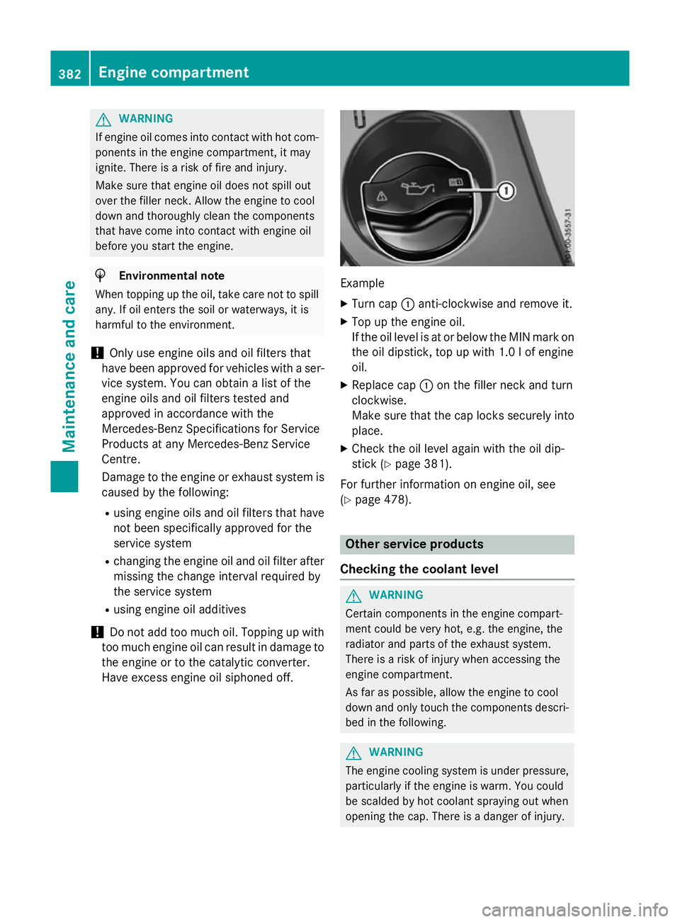
Have excess engine oil siphoned off. Example
X Turn cap :anti-clockwise and remove it.
X Top up the engine oil.
If the oil leve lisatorbelow the MIN mark on
the oil dipstick, top up with 1.0 lofe ngine
oil.
X Replace cap :on the filler neck and turn
clockwise.
Make sure that the cap locks securely into place.
X Check the oil level again with the oil dip-
stick (Y page 381).
For further information on engine oil, see
(Y page 478). Other service products
Checking the coolant level G
WARNING
Certain components in the engine compart-
ment could be very hot, e.g. the engine, the
radiator and parts of the exhaust system.
There is arisk of injury when accessing the
engine compartment.
As far as possible, allow the engine to cool
down and only touch the components descri- bed in the following. G
WARNING
The engine cooling system is under pressure, particularly if the engine is warm. You could
be scalded by hot coolant spraying out when
opening the cap. There is adanger of injury. 382
Engine compartmentMaintenance and care
Page 386 of 497
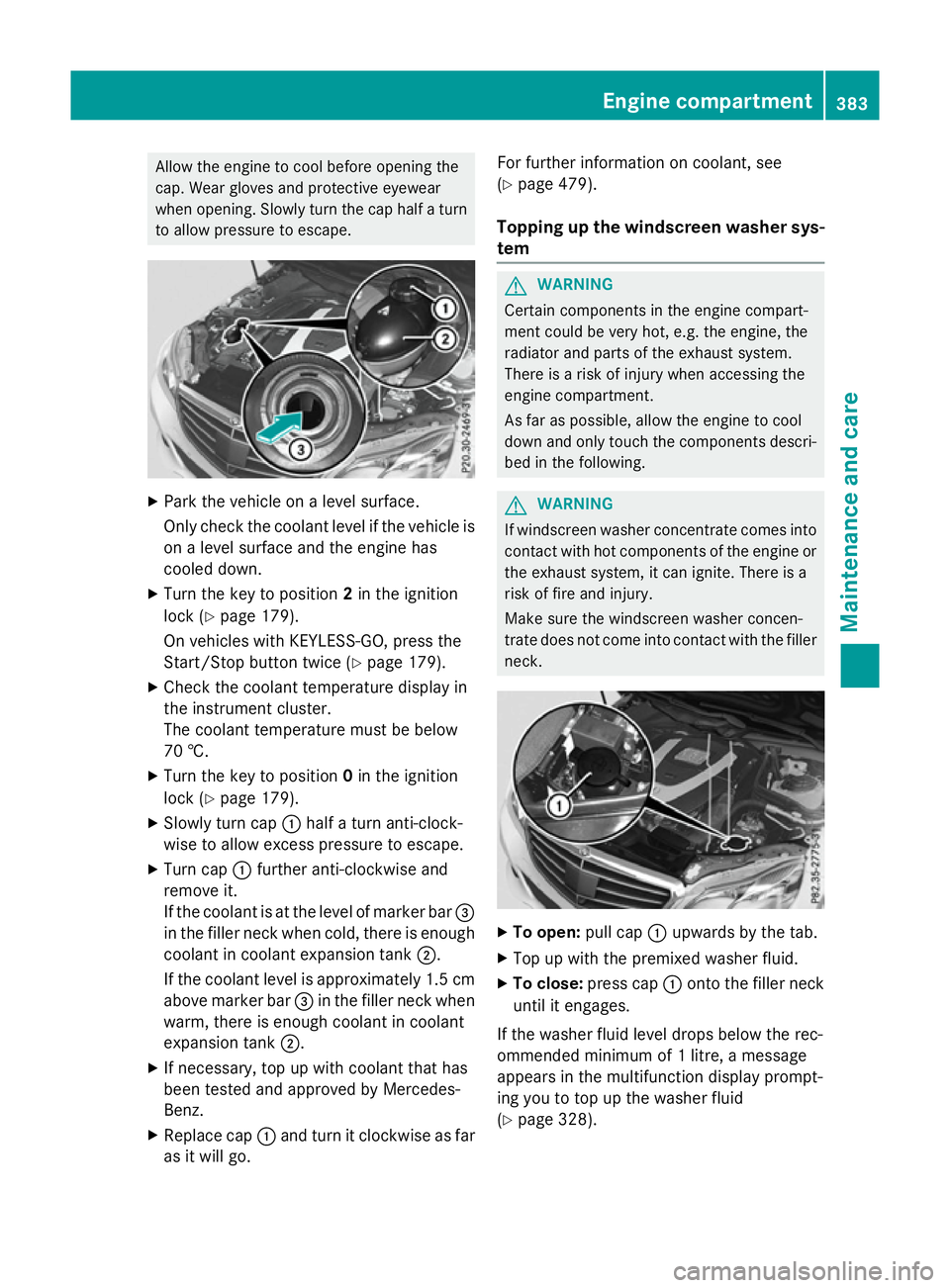
Allow the engine to coo
lbefore opening the
cap .Wearg love sa nd protective eyewear
when opening. Slowl yturn the cap half aturn
to allo wpressure to escape. X
Park the vehicl eonalevel surface.
Onl ycheck the coolant level if the vehicl eis
on alevel surface and the engine has
coole ddown.
X Turn the key to position 2in the ignition
lock (Y page 179).
On vehicles with KEYLESS-GO ,press the
Start/Stop button twice (Y page 179).
X Check the coolant temperature display in
the instrument cluster.
The coolant temperature must be below
70 †.
X Turn the key to position 0in the ignition
lock (Y page 179).
X Slowl yturn cap :half aturn anti-clock-
wise to allo wexcess pressure to escape.
X Turn cap :furthe ranti-clockwise and
remove it.
If the coolant is at the level of marker bar =
in the fille rneck when cold, ther eisenough
coolant in coolant expansio ntank ;.
If the coolant level is approximatel y1.5 cm
above marker bar =in the fille rneck when
warm, ther eisenoughcoolant in coolant
expansio ntank ;.
X If necessary ,top up with coolant tha thas
been teste dand approved by Mercedes-
Benz.
X Replace cap :and turn it clockwise as far
as it will go. For furthe
rinformatio noncoolant, see
(Y page 479).
Topping up the windscreen washe rsys-
tem G
WARNING
Certai ncomponents in the engine compart-
ment could be ver yhot, e.g .the engine ,the
radiato rand parts of the exhaus tsystem.
There is ariskofi njury when accessing the
engine compartment.
As far as possible, allo wthe engine to cool
down and onl ytouch the components descri-
be dint he following. G
WARNING
If windscree nwashe rconcentrate come sinto
contact with hot components of the engine or
the exhaus tsystem ,itc an ignite .There is a
ris koff irea nd injury.
Make sure the windscree nwashe rc oncen-
trate does not come into contact with the filler neck. X
To open: pull cap:upwards by the tab.
X Top up with the premixe dwashe rfluid.
X To close: press cap :onto the fille rneck
unti lite ngages.
If the washe rfluid level drops belo wthe rec-
ommende dminimu mof1l itre, am essage
appear sinthe multifunctio ndisplay prompt-
ing yo utotop up the washe rfluid
(Y page 328). Engine compartment
383Maintenance and care Z
Page 412 of 497
Fitting/removing th
etowing eye
Fitting th etowing eye G
WARNING
The exhaust tai lpipe may be extremely hot.
Ther eisar iskofb urning when removing the
rear cover.
Do no ttou ch th eexhaust tai lpipe. Use
extreme caution when removing th erear
cover. Towin
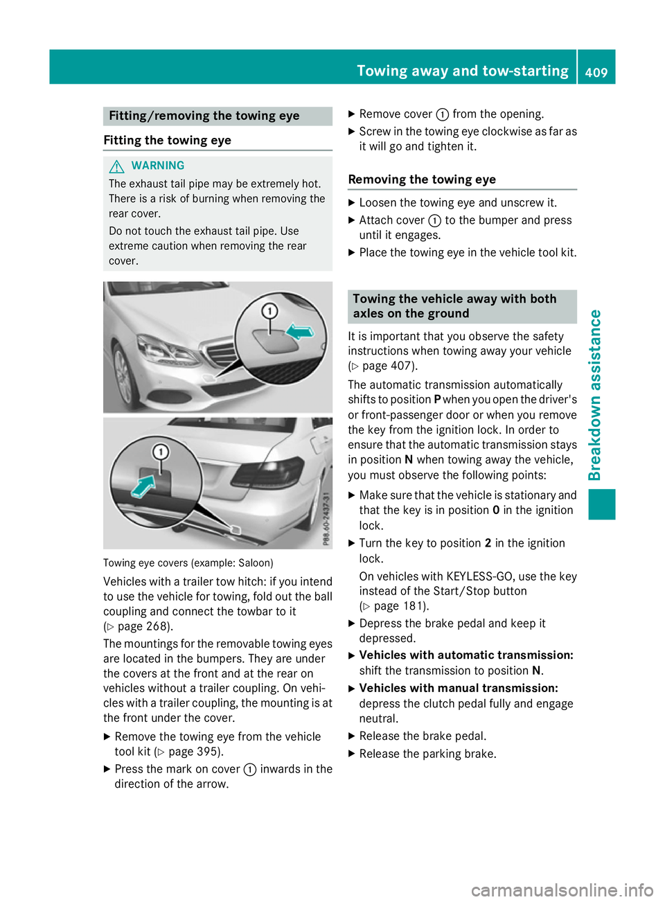
geye cover s(example: Saloon)
Vehicles wit hatrailer to whitch :ify ou intend
to use th evehicl efor towing, fol dout th eball
couplin gand connec tthe towbar to it
(Y page 268).
The mounting sfor th eremovable towin geyes
are locate dinthebumpers .They are under
th ec oversatt hefron tand at th erear on
vehicles without atrailer coupling. On vehi-
cle sw ithat railer coupling, th emounting is at
th ef ront under th ecover.
X Remove th etow inge ye from th evehicle
tool kit (Y page 395).
X Press th emarkonc over : inwards in the
direction of th earrow. X
Remove cover :from th eopening.
X Screw in th etow inge ye clockwise as far as
it will go and tighten it.
Removing th etowing eye X
Loosen th etow inge ye and unscrew it.
X Attac hcover : to th ebumper and press
until it engages.
X Plac ethe towin geye in th evehicl etoolkit. Towing th
evehicle awa ywith both
axles on th eground
It is important that you observ ethe safety
instruction swhen towin gaway your vehicle
(Y page 407).
The automatic transmission automatically
shifts to position Pwhen you open th edriver's
or front-passenger door or when you remove th ek eyfrom th eignition lock. In order to
ensure that th eautomatic transmission stays
in position Nwhen towin gaway th evehicle,
you must observ ethe followin gpoints:
X Mak esure that th evehicl eiss tationary and
that th ekeyis in position 0in th eignition
lock.
X Turn th ekeyto position 2in th eignition
lock.
On vehicles wit hKEYLESS-GO ,use th ekey
instead of th eStart/Sto pbutton
(Y page 181).
X Depress th ebrak epedal and keep it
depressed.
X Vehicles with automatic transmission:
shif tthe transmission to position N.
X Vehicles with manua ltra nsmission:
depress th eclutch pedal fully and engage
neutral.
X Releas ethe brak epedal.
X Releas ethe parking brake. Towin
gawaya nd tow-starting
409Breakdown assistance Z
Page 431 of 497
jack could tip ove
rwitht he vehicl eraised.
There is ariskofi njury.
Onl yposit iont he jack at the appropriate jack-
ing point of the vehicle. The base of the jack
must be positioned vertically, directl yunder
the jacking point of the vehicle.
Observe the following when raising the vehi-
cle:
R to rais ethe vehicle, onl yusethe vehicle-
specific jack tha thas been teste dand
approved by Mercedes-Benz. If the jack is
used incorrectly ,itcould tip ove rwhile the
vehicl eisraised.
R the jack is designe donlytor aiseand hold
the vehicl efor as hort time whil eawheel
is being changed. It is not suitabl efor per-
formin gmaintenance work under the vehi-
cle.
R avoi dchanging the whee lonuphilland
downhil lslope s.
R befor eraisi ng the vehicle, safeguard it from
rolling away by applying the parking brake
and positioning whee lchocks. Never
release the parking brake whil ethe vehicle
is raised.
R the jack must be place donafirm, flatand
non-sli psurface. On aloo se surface, a
large ,flatl oad- bearing underlay must be
used .Ona slippery surface, anon-slip
underlay must be used ,e.g.r ubbe rmats.
R do not us ewoode nblocks or similar
objects as ajack underlay .Otherwise, the
jack will not be able to achieve its load-
bearing capacity du etothe restricted
height.
R make sure tha tthe distance between the
undersid eofthe tyres and the ground does
not exceed 3cm.
R neve rplace your hands or fee tunder the
raised vehicle.
R do not li eunder the vehicle.
R do not start the engine when the vehicl eis
raised. R
do not open or close adoorort he boot lid/
tailgate when the vehicl eisraised.
R make sure tha tnopersons ar epresent in
the vehicl ewhent he vehicl eisraised.
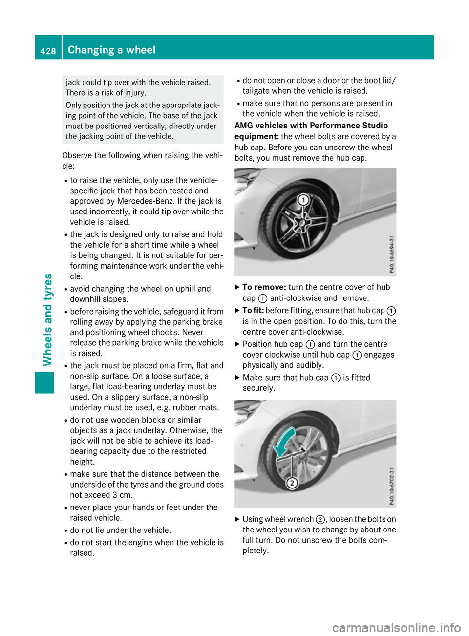
AM Gvehicle swithP erformanc eStudio
equipment: the wheelbolts ar ecovered by a
hu bc ap.B efore yo ucan unscrew the wheel
bolts ,you must remove the hu bcap. X
To remove: turnthe centre cove rofhub
cap :anti-clockwise and remove.
X To fit: beforefitting, ensur etha thub cap :
is in the open position. To do this, tur nthe
centre cove ranti-clockwise.
X Positio nhub cap :and tur nthe centre
cove rclockwise unti lhub cap :engages
physicall yand audibly.
X Make sure tha thub cap :is fitted
securely. X
Using whee lwrench ;,l oosent he bolts on
the whee lyou wish to change by abou tone
full turn. Do not unscrew the bolts com-
pletely. 428
Changin
gawheelWheels an dtyres
Page 432 of 497
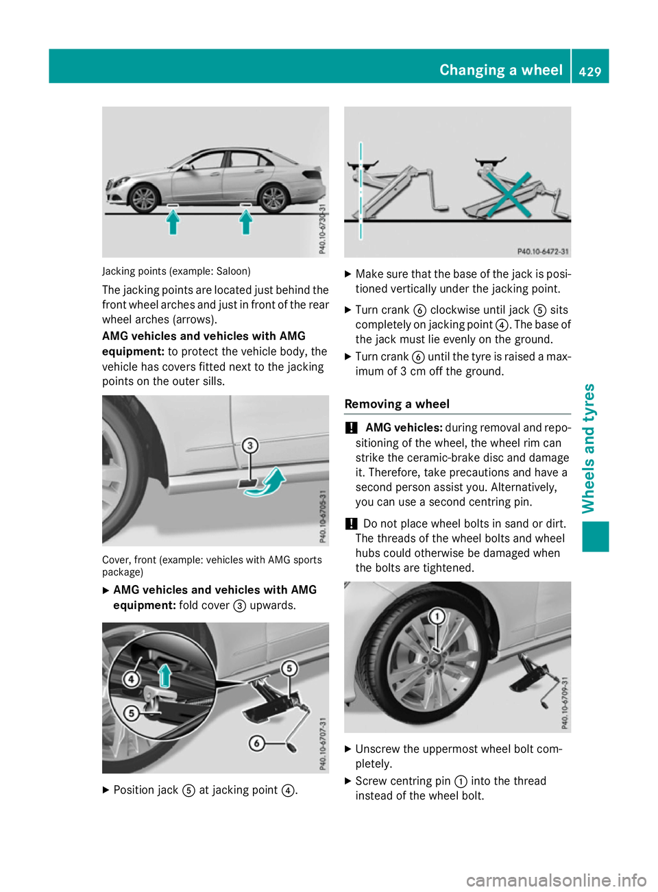
Jacking points (example: Saloon)
The jackin gpoints are located jus tbehin dthe
front wheel arches and jus tinfront of th erear
wheel arches (arrows).
AMG vehicles and vehicles with AMG
equipment: to protect thevehicle body, the
vehicle has covers fitted nex ttothejacking
points on th eoute rsills. Cover
,front (example: vehicles with AM Gsports
package)
X AMG vehicles and vehicles with AMG
equipment: fold cover=upwards. X
Position jack Aat jackin gpoint ?. X
Mak esure that th ebase of th ejackisp osi-
tioned vertically unde rthe jackin gpoint.
X Turn crank Bclockwis euntil jack Asits
completely on jackin gpoint ?.T he base of
th ej ackm ust lie evenly on th eground.
X Turn crank Buntil th etyreisr aisedam ax-
imum of 3cmoff theground.
Removing awheel !
AMG vehicles:
duringremoval and repo-
sitioning of th ewheel, th ewheel rim can
strik ethe ceramic-brake disc and damage
it. Therefore, tak eprecaution sand have a
second person assist you. Alternatively,
you can use asecond centring pin.
! Do not place wheel bolt
sinsandord irt.
The threads of th ewheel bolt sand wheel
hubs could otherwise be damaged when
th eb oltsa re tightened. X
Unscrew th euppermost wheel bolt com-
pletely.
X Screw centring pin :intot he thread
instead of th ewheel bolt. Changing
awheel
429Wheels and tyres Z
Page 433 of 497
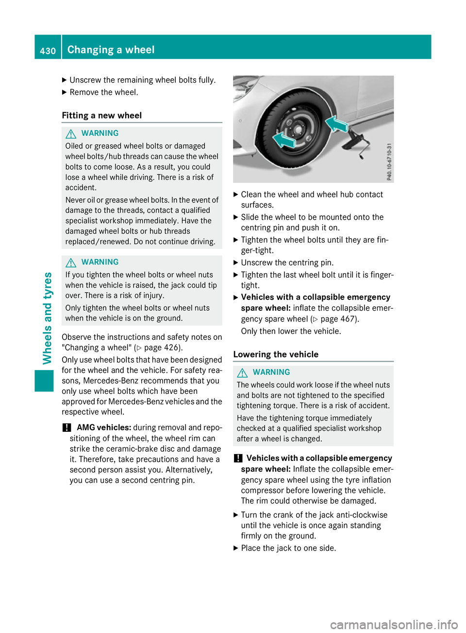
X
Unscrew the remaining wheel bolts fully.
X Remove the wheel.
Fitting anew wheel G
WARNING
Oiled or greased wheel bolts or damaged
wheel bolts/hub threads can cause the wheel bolts to come loose. As aresult, you could
lose awheel while driving. There is arisk of
accident.
Never oil or grease wheel bolts. In the event of damage to the threads, contact aqualified
specialist workshop immediately.H ave the
damagedw heel bolts or hub threads
replaced/renewed. Do not continue driving. G
WARNING
If you tighten the wheel bolts or wheel nuts
when the vehicle is raised, the jack could tip
over. There is arisk of injury.
Only tighten the wheel bolts or wheel nuts
when the vehicle is on the ground.
Observe the instructions and safety notes on "Changing awheel" (Y page 426).
Only use wheel bolts that have been designed
for the wheel and the vehicle. For safety rea-
sons, Mercedes-Benz recommends that you
only use wheel bolts which have been
approved for Mercedes-Benz vehicles and the
respective wheel.
! AMG vehicles:
during removal and repo-
sitioning of the wheel, the wheel rim can
strike the ceramic-brake disc and damage
it. Therefore, take precautions and have a
second person assist you. Alternatively,
you can use asecond centring pin. X
Cleant he wheel and wheel hub contact
surfaces.
X Slide the wheel to be mounted onto the
centring pin and push it on.
X Tighten the wheel bolts until they are fin-
ger-tight.
X Unscrew the centring pin.
X Tighten the last wheel bolt until it is finger-
tight.
X Vehiclesw ithacollapsible emergency
spare wheel: inflate the collapsible emer-
gency spare wheel (Y page 467).
Only then lower the vehicle.
Lowering the vehicle G
WARNING
The wheels could work loose if the wheel nuts and bolts are not tightened to the specified
tightening torque. There is arisk of accident.
Have the tightening torque immediately
checked at aqualified specialist workshop
after awheel is changed.
! Vehiclesw
ithacollapsible emergency
spare wheel: Inflate the collapsible emer-
gency spare wheel using the tyre inflation
compressor before lowering the vehicle.
The rim could otherwise be damaged.
X Turn the crank of the jack anti-clockwise
until the vehicle is once agains tanding
firmly on the ground.
X Place the jack to one side. 430
Changing
awheelWheels and tyres
Page 469 of 497
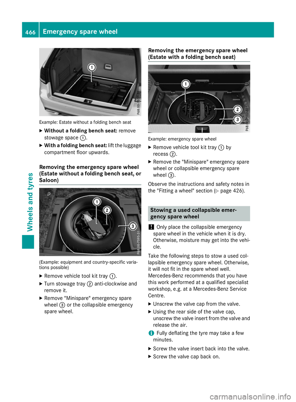
Example: Estate withou
tafolding bench seat
X Without afolding benc hseat:remove
stowag espace :.
X With afolding benc hseat:lift the luggage
compartment floor upwards.
Removing the emergenc yspare wheel
(Estate withou tafolding benc hseat, or
Saloon) (Example: equipment and country-specific varia-
tions possible)
X Remov evehicl etool kit tray :.
X Turn stowag etray ;anti-clockwise and
remove it.
X Remov e"Minispare" emergency spare
wheel =or the collapsibl eemergency
spare wheel. Removing the emergenc
yspare wheel
(Estate with afolding benc hseat) Example: emergency spare wheel
X Remove vehicl etool kit tray :by
recess ;.
X Remove the "Minispare" emergency spare
whee lorcollapsibl eemergency spare
wheel =.
Observ ethe instructions and safety notes in
the "Fitting awheel "sectio n(Ypage 426). Stowing
ausedc olla psibl eemer-
genc yspare wheel
! Onl
yplace the collapsibl eemergency
spare whee linthe vehicl ewhenitisd ry.
Otherwise, moisture ma ygetinto the vehi-
cle.
Take the following step stostowausedc ol-
lapsibl eemergency spare wheel. Otherwise,
it will not fit in the spare whee lwell.
Mercedes-Benz recommends tha tyou have
thi sw orkp erformed at aquali fied specialist
workshop ,e.g.ata Mercedes-Benz Service
Centre.
X Unscrew the valve cap from the valve.
X Using the rea rsideoft he valve cap,
unscrew the valve insert from the valve and release the air.
i Fully deflating the tyr
emaytake afew
minutes.
X Screw the valve insert back into the valve.
X Screw the valve cap back on. 466
Emergenc
yspare wheelWheel sand tyres