wiring MERCEDES-BENZ E-CLASS ESTATE 2015 Owners Manual
[x] Cancel search | Manufacturer: MERCEDES-BENZ, Model Year: 2015, Model line: E-CLASS ESTATE, Model: MERCEDES-BENZ E-CLASS ESTATE 2015Pages: 497, PDF Size: 16.23 MB
Page 48 of 497

See "Children in the vehicle" for further infor-
mation on children travelling in the vehicl eas
well as on child restraint systems
(Y page 58). Important safety notes
G
WARNING
If the restraint system is modified ,itmay no
longer work as intended .The restraint system
may then not perfor mits intended protective
function by failing in an accident or triggering
unexpectedly, for example. There is an
increased ris kofinjury ,possibly eve nfatal.
Neve rmodify parts of the restraint system. Do
not attempt to modify the wiring as well as
electronic components or thei rsoftware.
If it is necessary to modify an airba gsystem to
accommodate aperson with disabilities, con-
tact aMercedes-Benz Service Centre for
details. Restrain
tsystem warnin glamp
The functions of the restraint system are
checke dafterthe ignition is switche donand
at regular interval swhile the engine is run-
ning. Therefore, malfunctions can be detec-
ted in goo dtime.
The 6 restraint system warning lamp in
the instrument cluster lights up when the igni- tion is switche don. It goe soutno later tha na
few seconds afte rthe vehicl eisstarted. The
components of the restraint system are in
operationa lreadiness.
Am alfunction ha soccurred if the 6
restraint system warning lamp:
R doe snot light up afte rthe ignition is
switche don
R doe snot go ou tafte raf ew seconds with
the engine running
R lights up agai nwhile the engine is running G
WARNING
If the restraint system is malfunctioning,
restraint system components may be trig-
gered unintentionally or might not be trig-
gered at al linthe event of an accident with a
high rate of vehicl edeceleration. Thi scan
effect belt tensioner sorairbags, for example.
There is an increased ris kofserious or even
fata linjuries.
Hav ethe restraint system checke dand
repaired immediatel yataqualified specialist
workshop. PASSENGER AI
RBAG OF Find icator
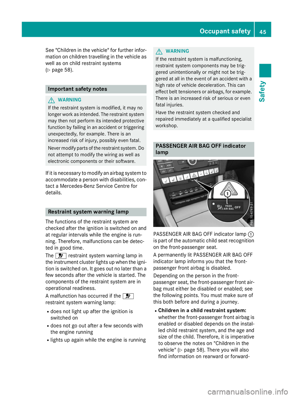
lamp PASSENGER AIR BAG OFF indicator lamp
:
is part of the automatic child sea trecognition
on the front-passenger seat.
Ap ermanently li tPASSENGER AIR BAG OFF
indicator lamp informs yo uthatthe front-
passenger front airba gisdisabled.
Depending on the person in the front-
passenger seat, the front-passenger front air-
ba gm uste ither be disabled or enabled ;see
the following points. Yo umustm ake sure of
this both before and during ajourney.
R Childre ninachild restrain tsystem:
whethe rthe front-passenger front airba gis
enabled or disabled depends on the instal- le dc hild restraint system, and the ag eand
size of the child .Therefore, it is imperative
to observe the notes on "Children in the
vehicle" (Y page 58). There yo uwilla lso
find information on rearward or forward- Occupant safety
45Safety Z
Page 474 of 497

sion surrounding the possible health risk
posed by electromagnetic fields.
Observe the notes on operating mobile
phones (Y page 367).
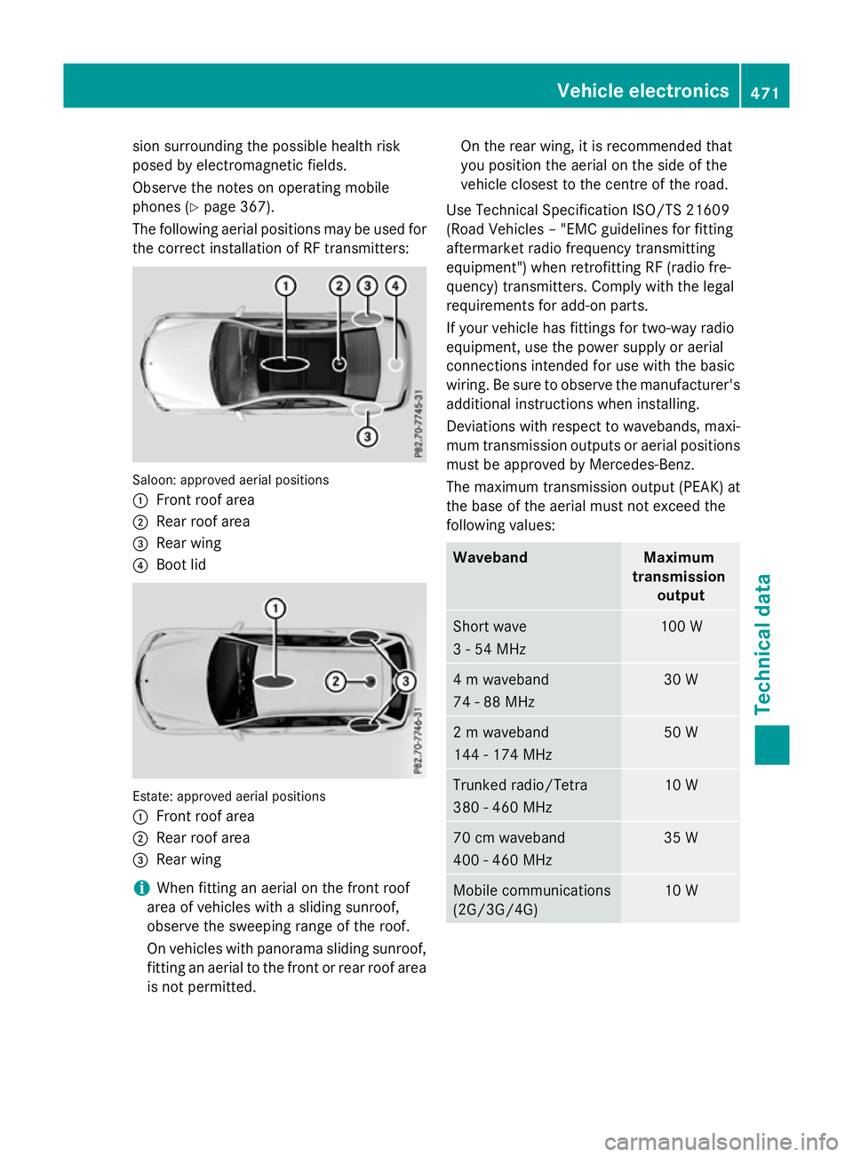
The following aerialp ositions may be used for
the correct installation of RF transmitters: Saloon: approved aerial positions
:
Front roof area
; Rear roof area
= Rear wing
? Boot lid Estate: approved aerial positions
:
Front roof area
; Rear roof area
= Rear wing
i When fitting an aerialont
he front roof
area of vehicles with asliding sunroof,
observe the sweeping range of the roof.
On vehicles with panorama sliding sunroof,
fitting an aerialtot he front or rear roof area
is not permitted. On the rear wing, it is recommended that
you position the aerialont he side of the
vehicle closest to the centre of the road.
Use Technical Specification ISO/TS 21609
(RoadV ehicles–"EMC guidelines for fitting
aftermarket radio frequency transmitting
equipment") when retrofitting RF (radio fre-
quency) transmitters. Comply with the legal
requirements for add-on parts.
If your vehicle has fittings for two-way radio
equipment, use the power supplyora erial
connections intended for use with the basic
wiring. Be sure to observe the manufacturer's additional instructions when installing.
Deviations with respect to wavebands, maxi-
mum transmission outputs or aerialp ositions
must be approved by Mercedes-Benz.
The maximum transmission output (PEAK) at
the base of the aerialm ust not exceed the
following values: Waveband Maximum
transmission output Short wave
3-54M
Hz 100 W
4mw
aveband
74 -88M Hz 30 W
2mw
aveband
144 -174 MHz 50 W
Trunked radio/Tetra
380
-460 MHz 10 W
70 cm waveband
400
-460 MHz 35 W
Mobile communications
(2G/3G/4G) 10 WVehicle electronics
471Technical data Z