ECU MERCEDES-BENZ E-CLASS SALOON 2017 Workshop Manual
[x] Cancel search | Manufacturer: MERCEDES-BENZ, Model Year: 2017, Model line: E-CLASS SALOON, Model: MERCEDES-BENZ E-CLASS SALOON 2017Pages: 497, PDF Size: 10.38 MB
Page 251 of 497
%
Accessories can be connected tothe perma‐
nent po wer supp lyup to180W, and tothe
po we r supp lythat is swit ched on via the igni‐
tion loc k.
Un coupling a trailer &
WARNING Risk of being crushed and
becoming trapped when uncoupling a
trailer
When uncoupling a trailer wi than engaged
ine rtia-activated brake, your hand may
become trapped between theve hicle and the
trailer dr awbar. #
Do not uncouple trailers with an
engaged overrun brake. &
WARNING Risk of becoming trapped
when disconnecting the trailer cable
Ve hicles with le vel control sy stem: the
ve hicle lo werswhen the trailer cable is dis‐
connected. This could
result in you or other people
becoming trapped if your or their limbs are
between theve hicle body and the tyres or
underneath theve hicle. #
Make sure nobody is underneath the
ve hicle or in the immediate vicinity of
th e wheel ar ches when you disconnect
th e trailer cable. *
NO
TEDama getothere ar bumper from
ins talling adap ter cables or adapte r plugs The
following parts could be damaged when
re tracting the ball neck fully electrically:
R bumper
R adap ter cable
R adapte r plug #
Alw aysre mo vethe adap ter cable or
adapte r plug before retracting the ball
neck fully electrically. #
Safeguard the trailer against rolling away. #
Disconnect the electrical connection
between theve hicle and the trailer. #
Uncouple the trailer. #
Place the co ver on the ball head. Bicycle
rack &
WARNING Risk of an accident when
using the bicycle rack incor rectly
The bicycle rack may become de tach ed from
th eve hicle in thefo llowing cases:
R the permissible load capacity of the
trailer hitch is exceeded.
R the bicycle rack is used incor rectl y.
R the bicycle rack is secured tothe ball
neck beneath the ball head.
Obser vethefo llowing foryo ur ow n sa fety
and that of other road users:
R always adhere tothe permissible load
capacity of the trailer hitch. 248
Driving and pa rking
Page 253 of 497
Note
s on loads
The larger the dis tance between the load's
cent reof gr avity and the ball head, the greater
th e load on the trailer hitch.
Obser vethefo llowing no tes:
R mount heavy bicycles as close totheve hicle
as possible.
R always distribute the load on the bicycle rack
as eve nly as possible across theve hicle's
longitudinal axis.
Mercedes-Benz recommends removing all
de tach able parts from the bicycles, e.g. bask ets,
ch ild seats or rech arge able bat teries, before
loading them onto the bicycle rack . This
impr ovesth e wind resis tance and centre of gr av‐
ity of the bicycle rack.
Alw ays secure the bicycles toprev ent them from
moving around and check they are secured at
re gular inter vals.
Do not use tarp aulins or other co vers. The han‐
dling characteristics and rear view may be impaired. In addition,
the wind resis tance and
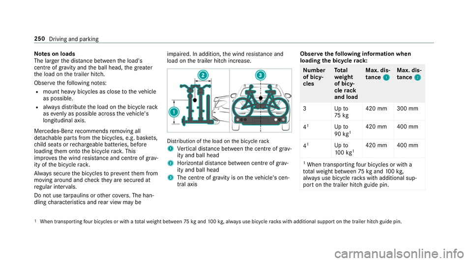
load on the trailer hitch increase. Distribution of
the load on the bicycle rack
1 Vertical dis tance between the cent reof gr av‐
ity and ball head
2 Horizon tal dis tance between centre of gr av‐
ity and ball head
3 The centre of gr avity is on theve hicle's cen‐
tral axis Obser
vethefo llowing information when
loading the bicycle rack: Nu
mber
of bicy‐
cles To
tal
we ight
of bicy‐
cle rack
and load Max. dis‐
tance
1 1Max. dis‐
tance
2 2
3U pto
75 kg 420 mm 300 mm
4 1
Upto
90 kg1 420 mm 400 mm
4 1
Upto
10 0kg 1 420 mm 400 mm
1 When transpo rting four bic ycles or with a
tot alwe ight between 75kgand 100kg,
alw ays use bicycle rack s with additional sup‐
port on the trailer hitch guide pin. 1
When transporting four bicycles or with a totalwe ight between 75kgand 100kg , alw ays use bicycle rack s with additional support on the trailer hitch guide pin. 250
Driving and parking
Page 255 of 497
R
Limiter (→ page 202)
R Active Dis tance Assi stDISTRONIC
(→ page 205)
* NO
TEEngine dama gedue toexc essively
high engine speeds The engine will be damaged if
you drive with
th e engine in theov errevving range. #
Do not drive wi th the engine in theove r‐
re vving range. The fuel supply is inter
rupted toprotect the
engine when there d band in rev counter 3
(o ve rrev ving range) is reached.
During no rmal operating conditions, coolant
te mp erature display 4may rise to120 °C. &
WARNING Danger of bu rns when open‐
ing the bonn et
If yo u open the engine bonn etwhen the
engine has overheated or during a fire inthe
engine compartment, you could come into
contact with hot gases or other escaping
operating fluids. #
Before opening the bonn et, allow the
engine tocool down. #
Intheeve nt of a fire inthe engine com‐
partment, keep the engine bonn et
closed and call thefire service. Ve
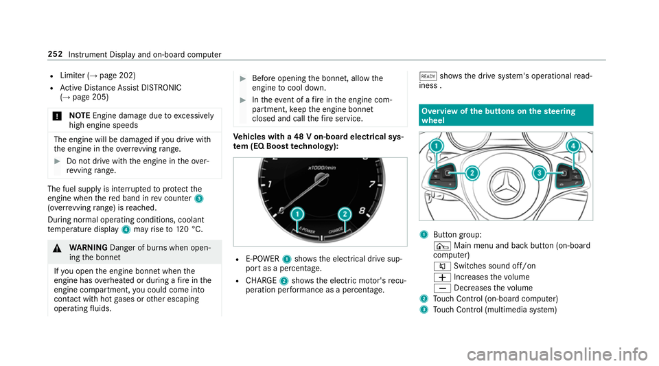
hicles with a 48 V on-board electrical sys‐
te m (EQ Boo sttech nology): R
E-POWER 1shows th e electrical drive sup‐
port as a percentage.
R CHARGE 2showsthe electric mo tor's recu‐
peration per form ance as a percen tage. õ
showsthe drive sy stem's operational read‐
iness . Overview of
the but tons on thest eering
wheel 1
Button group:
¤ Main menu and ba ckbutton (on-board
computer)
8 Switches sound off/on
W Increases thevo lume
X Decreases thevo lume
2 Touch Control (on-board co mputer)
3 Touch Control (multimedia sy stem) 252
Instrument Display and on-board computer
Page 260 of 497
R
Grey radar waves next tovehicle: Blind Spot
Assist activated
R Green radar waves next tovehicle: Blind Spot
Assist active
R Active Dis tance Assi stDISTRONIC displa ys
( → page 205) Calling up displa
ysintheTr ip menu On-board computer:
, Trip
% Ve
hicles with an instrument display in
th e widescreen cockpit: whenyou ha ve
th e design set toProgressive ,yo u can view
information on the journey in the left-hand
area of the instrument displa y.#
Toselect a displa y:swipe upwards or down‐
wa rds on the left-hand Touch Control.
Displa ysintheTripmenu:
R standard display
R range and cur rent fuel consu mption When
gliding mode is active (→ page175),
Gliding mode is displayed ins tead of the cur‐
re nt fuel consu mption.
A recuperation displ ayis also available for
cer tain engines. If there is only a small
amount of fuel left in the fuel tank, the dis‐
play sho wsave hicle being refuelled ins tead
of thera nge.
R ECO displ ay (→page 168)
R Trip computer From startandFrom reset
R Digital speedom eter
% Ve
hicles with an Instrument Display in
th eWi descreen Co ckpit: the digital speed‐
ome ter only appears in theClassic andSport
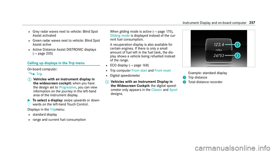
designs. Example:
standard display
1 Trip dis tance
2 Total dis tance recorder Instrument Display and on-board compu
ter257
Page 283 of 497
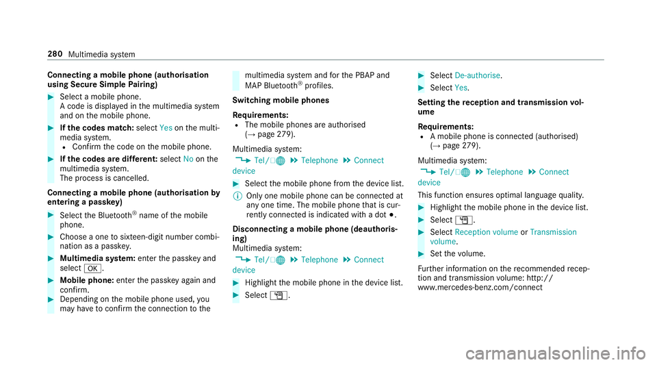
Connecting a mobile phone (au
thorisation
using Secure Simple Pairing) #
Select a mobile phone.
A code is displa yed in the multimedia sy stem
and on the mobile phone. #
Ifth e codes match: selectYesonthe multi‐
media sy stem.
R Confirm the code on the mobile phone. #
Ifth e codes are dif fere nt: select Noonthe
multimedia sy stem.
The process is cancelled.
Connecting a mobile phone (authorisation by
entering a passk ey)#
Select the Blue tooth®
name of the mobile
phone. #
Choose a one tosixteen-digit number combi‐
nation as a passk ey.#
Multimedia sy stem: enter the passk eyand
select a. #
Mobile phone: enterthe passk eyagain and
con firm. #
Depending on the mobile phone used, you
may ha vetoconfirm the connection tothe multimedia sy
stem and forth e PBAP and
MAP Blue tooth®
profiles.
Switching mobile phones
Requ irements:
R The mobile phones are authorised
(→ page 279).
Mul timedia sy stem:
, Tel/ ®.
Telephone .
Connect
device #
Select the mobile phone from the device list.
% Only one mobile phone can be connected at
any one time. The mobile phone that is cur‐
re ntly connected is indica ted with a dot #.
Disconnecting a mobile phone (deauthoris‐
ing)
Multimedia sy stem:
, Tel/ ®.
Telephone .
Connect
device #
Highlight the mobile phone in the device list. #
Select G. #
Select De-authorise. #
Select Yes.
Setting there ception and transmission vol‐
ume
Re quirements:
R A mobile phone is connec ted (authorised)
(→ page 279).
Mul timedia sy stem:
, Tel/ ®.
Telephone .
Connect
device
This function ensures optimal language qualit y. #
Highlight the mobile phone in the device list. #
Select G. #
Select Reception volume orTransmission
volume . #
Set thevo lume.
Fu rther information on there commended recep‐
tion and transmission volume: http://
www.me rcedes-benz.com/connect 280
Multimedia sy stem
Page 302 of 497
Switching
toMedia Inter face
Multimedia sy stem:
, Media .
Media .
Media Interface 1 #
Connect the data storage medium with the
USB port (→ page 297).
Pla yable music files are pla yed bac k.
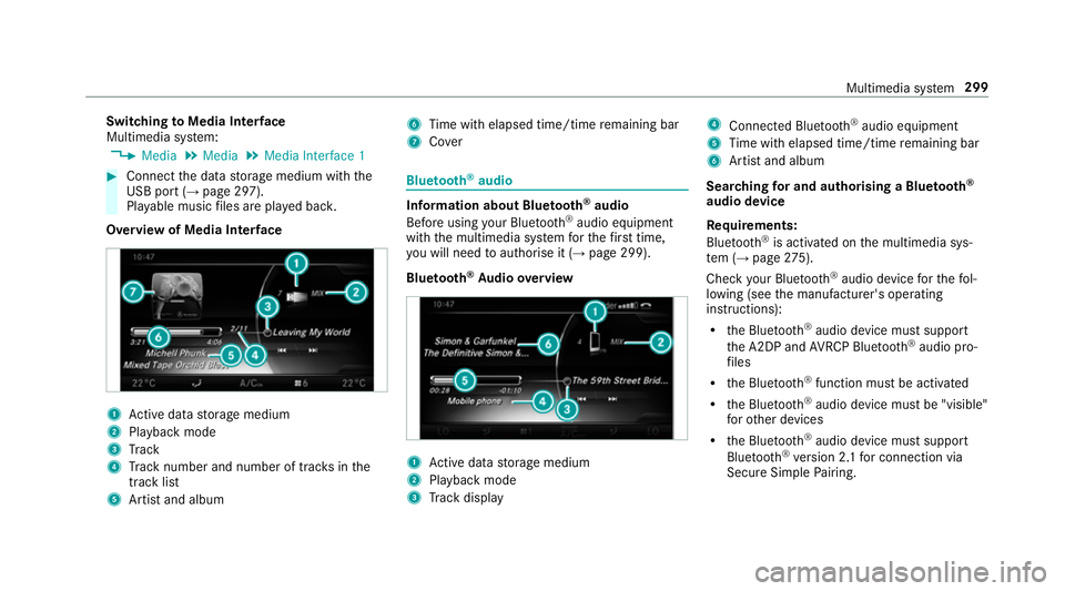
Overview of Media Inter face 1
Active da tastorage medium
2 Playback mode
3 Track
4 Track number and number of trac ksinthe
track li st
5 Artist and album 6
Time with elapsed time/time remaining bar
7 Cover Blue
tooth ®
audio Information about Blue
tooth ®
audio
Before using your Blue tooth®
audio equipment
with the multimedia sy stem forth efirs t time,
yo u will need toauthorise it (→ page 299).
Blu etoo th®
Au dio overview 1
Active da tastorage medium
2 Playback mode
3 Track display 4
Connec ted Blue tooth®
audio equipment
5 Time with elapsed time/time remaining bar
6 Artist and album
Sear ching for and authorising a Blue tooth ®
audio device
Requ irements:
Blue tooth ®
is activated on the multimedia sys‐
te m (→ page275).
Che ckyour Blue tooth®
audio device forth efo l‐
lowing (see the manufacturer's operating
instructions):
R the Blue tooth®
audio device must suppo rt
th e A2DP and AVRC P Blue tooth®
audio pro‐
fi les
R the Blue tooth®
function must be activated
R the Blue tooth®
audio device must be "visible"
fo rot her devices
R the Blue tooth®
audio device must suppo rt
Blu etoo th®
ve rsion 2.1 for connection via
Secure Simple Pairing. Multimedia sy
stem 299
Page 303 of 497
Multimedia sy
stem:
, Media .
Media .
Bluetooth
audio .
Options .
Bluetooth audio devi-
ces .
Search for audio devices #
Select Start search.
The multimedia sy stem sear ches for Blue‐
tooth ®
audio devices within range and adds
th em tothe Blue tooth ®
device list.
Option 1: Secure Simple Pairing #
Select the Blue tooth®
audio device.
Auth orisation starts.
A code is displa yed on the multimedia sys‐
te m and on the mobile phone. #
Confirm on bo thdevices if the codes are
identical.
Option 2: entering the passk ey #
Select the Blue tooth®
audio device.
The input menu forth e passk eyis displa yed. #
Multimedia sy stem: choose a one tosix‐
te en-digit number combination as a passk ey. #
Select OK once all the numbers ha vebeen
entered. #
Mobile phone: enterthe same passk eyand
con firm your entr y.
Af ter successful auth orisation,the Blue‐
tooth ®
audio equipment is connec ted and
st arts playing.
Establishing a connection from the Blue‐
to oth ®
audio equipment
The Blue tooth®
device name of the multimedia
sy stem is MB BLUETOOTH. #
Select Connect via audio device . #
Start the authorisation on your Blue tooth®
audio equipment (see the manufacturer's
operating instructions).
Af ter successful auth orisation,the Blue‐
tooth ®
audio equipment is connec ted and
st arts playing.
Wi th some Blue tooth®
audio equipment, play‐
back must be initially star ted on the device itself
so that the multimedia sy stem can play the
audio files. %
Device-specific information on authorising
and connecting Blue tooth®
-capable mobile
phones can be obtained at http://
ww w.mercedes-benz.com/connect or from a
Mercedes-Benz Service Centre.
Ac tivating Blue tooth ®
audio
Multimedia sy stem:
, Media .
Media #
Select Bluetooth audio.
The multimedia sy stem activates the connec‐
te d Blue tooth®
audio equipment.
Ad justing the volume on the Blu etoo th®
audio equipment
Multimedia sy stem:
, Media .
Media .
Bluetooth
audio .
Options .
Volume #
Select Standard orBoost .
% On some Blue tooth®
audio equipment, the
vo lume can also be adjus ted on the device
(see the manufacturer's operating instruc‐
tions). 300
Multimedia sy stem
Page 337 of 497
R
Alw ays make sure that nei ther you nor the
battery is elect rostatically charge d.
R Keep away from fire and naked flames.
R Do not lean over the batter y.
R When charging: only use battery charge rs
te sted and appr ovedby Mercedes-Benz and
re ad the battery charge r's operating instruc‐
tions before charging the batter y.
Obser vethe additional following points during
st arting assis tance:
R Starting assis tance may only be pr ovided
using batteries with a nominal voltage of
12 V.
R The vehicles must not touch.
R Petrol engine: only acceptstarting assis‐
ta nce if the engine and exhaust sy stem are
cold. #
Secure theve hicle byapplying the electric
parking brake. #
Automatic transmission: shiftthe transmis‐
sion toposition j. #
Manual transmission: shift into neutral. #
Make sure that the ignition and all electrical
consumers are switched off. #
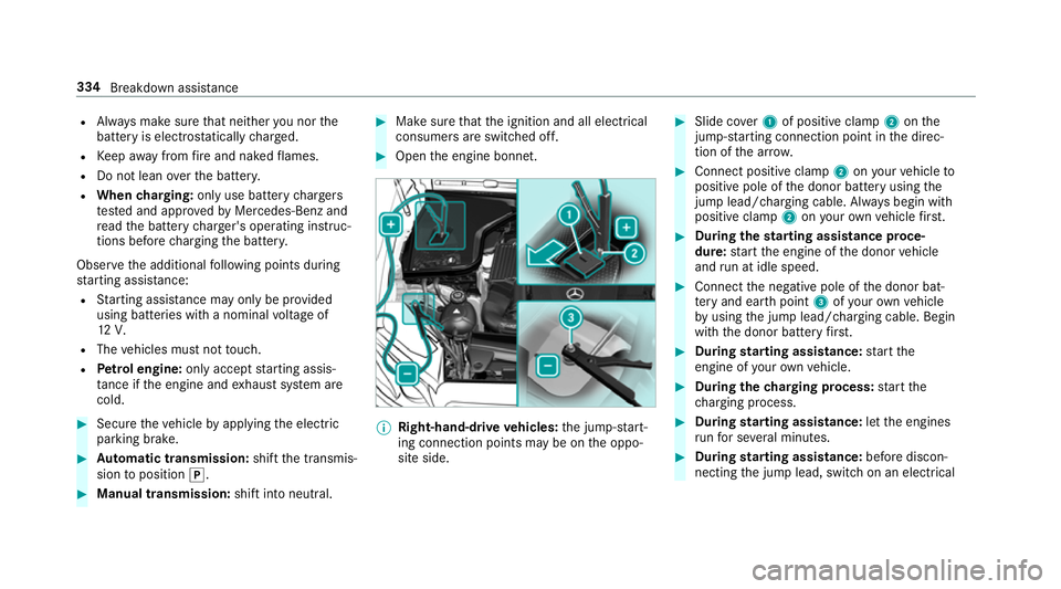
Open the engine bonn et. %
Right-hand-drive vehicles: the jump-s tart‐
ing connection points may be on the oppo‐
site side. #
Slide co ver1 of positive clamp 2onthe
jump-s tarting connection point in the direc‐
tion of the ar row. #
Connect positive clamp 2onyour vehicle to
positive pole of the donor battery using the
jump lead/charging cable. Alw ays begin with
positive clamp 2onyour ow nve hicle firs t. #
During thest arting assi stance proce‐
dure: start the engine of the donor vehicle
and run at idle speed. #
Connect the negative pole of the donor bat‐
te ry and ear thpoint 3ofyour ow nve hicle
by using the jump lead/charging cable. Begin
with the donor battery firs t. #
During starting assi stance: start the
engine of your ow nve hicle. #
During thech arging process: start the
ch arging process. #
During starting assi stance: letthe engines
ru nfo r se veral minutes. #
During starting assi stance: before discon‐
necting the jump lead, switch on an electrical 334
Breakdown assis tance
Page 341 of 497
#
Vehicles with manual transmission:
switch on the ignition, otherwise thesteering
wheel locking may engage. &
WARNING Risk of accident due tolimi‐
te d saf ety-re lated functions during the
to wing process
Saf ety-re lated functions are limited or no lon‐
ge rav ailable in thefo llowing situations:
R the ignition is switched off.
R the brake sy stem or po werst eering sys‐
te m is malfunctioning.
R the energy supply or the on-board electri‐
cal sy stem is malfunctioning.
When your vehicle is then towe daw ay, signif‐
icantly more ef fort may be requ ired tosteer
and brake than is no rmally requ ired. #
Use a tow bar. #
Make sure that thesteering wheel can
mo vefreely, before towing theve hicle
aw ay. *
NO
TEDama gedue toexcessive tracti ve
po wer If
yo u pull away sharpl y,the tractive po wer
may be too high and theve hicles could be
damaged. #
Pull away slowly and smoo thly. Loading the
vehicle for transport #
Obser vethe no tes on towing away
( → page 336). #
Connect theto w bar totheto wing eyeto
load theve hicle.
% You can also attach theto w bar tothe trailer
hitch. #
Vehicles with automatic transmission:
shift the automatic transmission toposition
i.
% Ve
hicles with automatic transmission:
th e automatic transmission may be loc ked in
position jintheeve nt of dama getothe
electrical sy stem. Toshift toi , pr ovide the on-board electrical sy
stem with po wer
( → page 332). #
Vehicles with manual transmission: shift
to neutral. #
Load theve hicle onto the transpor ter. #
Vehicles with automatic transmission:
shift the automatic transmission toposition
j. #
Vehicles with manual transmission:
engage firs t or reve rsege ar. #
Use the electric parking brake tosecure the
ve hicle and pr event it from rolling away. #
Only secure theve hicle bythe wheels.
Ve hicles with ADS PLUS (Adaptive Damping
Sy stem PLUS) &
WARNING Risk of an accident when
transporting vehicles with Adaptive
Damping Sy stem PLUS
The reduced damping forc es on theve hicle
being transpor ted can cause theve hicle/
trailer combination tostart toswing. 338
Breakdown assis tance
Page 342 of 497
As a
result, when transporting vehicles with
th eAd aptive Damping Sy stem PLUS, the
ve hicle/trailer combination may start toskid.
Consequentl y,yo u could lose cont rol of your
ve hicle. #
When transporting, ensure that:
R theve hicle has been loaded onto
th e transpor ter cor rectly
R theve hicle is secured at all four
wheels with suitable tensioning
st ra ps
R the maximum permissible speed of
60 km/h is not exceeded when
transporting *
NO
TEDama getotheve hicle from secur‐
ing it incor rectly #
After loading, theve hicle must be
secured on all four wheels. Otherwise,
th eve hicle could be damaged. #
A minimum dis tance of 20 cm up wards
and 10cm down wards must be kept to
th e transport platform. #
Secure theve hicle on all four wheels af ter
loading.
4MATIC vehicles/ vehicles with automatic
transmission #
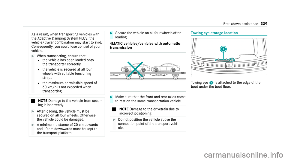
Make sure that the front and rear axles come
to rest on the same transpor tation vehicle.
* NO
TEDama getothe driv etra in due to
incor rect positioning #
Do not position theve hicle abo vethe
connection point of the transport vehi‐
cle. To
wing eyesto rage location To
wing eye1 is attached tothe edge of the
boot under the boot floor. Breakdown assis
tance 339