park assist MERCEDES-BENZ E-CLASS SALOON 2017 Owners Manual
[x] Cancel search | Manufacturer: MERCEDES-BENZ, Model Year: 2017, Model line: E-CLASS SALOON, Model: MERCEDES-BENZ E-CLASS SALOON 2017Pages: 497, PDF Size: 10.38 MB
Page 10 of 497
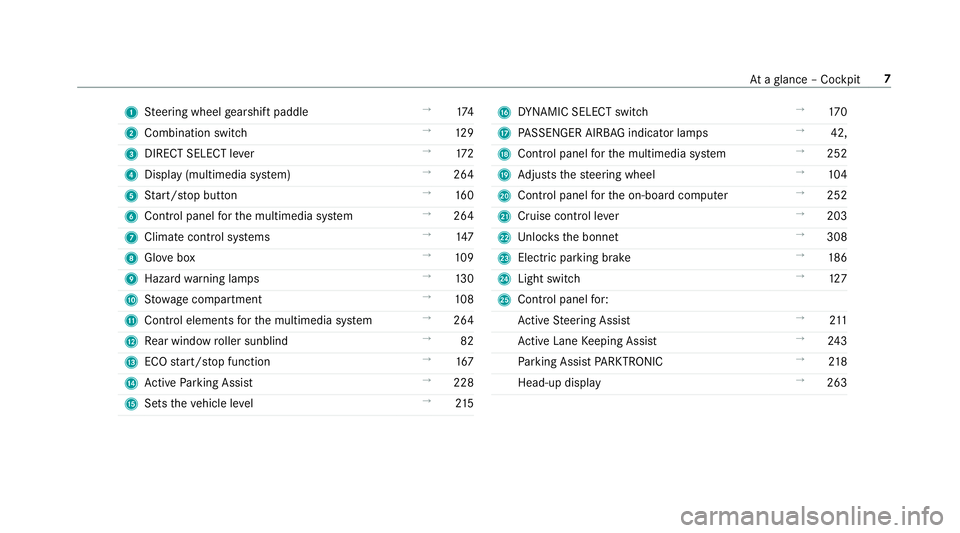
1
Steering wheel gearshift paddle →
174
2 Combination swit ch →
12 9
3 DIRECT SELECT le ver →
172
4 Displ ay(multimedia sy stem) →
264
5 Start/ stop button →
16 0
6 Control panel forth e multimedia sy stem →
264
7 Climate control sy stems →
147
8 Glovebox →
109
9 Haza rdwa rning lamps →
13 0
A Stow age compartment →
108
B Control elements forth e multimedia sy stem →
264
C Rear wind ow roller sunblind →
82
D ECO start/ stop function →
167
E Active Parking Assist →
228
F Sets theve hicle le vel →
215 G
DYNA MIC SELECT switch →
17 0
H PASSENGER AIRB AGindicator lamps →
42,
I Cont rol panel forth e multimedia sy stem →
252
J Adjusts thesteering wheel →
104
K Control panel forth e on-board computer →
252
L Cruise control le ver →
203
M Unloc ksthe bonn et →
308
N Electric parking brake →
186
O Light switch →
127
P Control panel for:
Ac tive Steering Assist →
211
Ac tive Lane Keeping Assist →
24 3
Pa rking Assist PARKTRONIC →
218
Head-up display →
263 At
aglance – Cockpit 7
Page 12 of 497
1
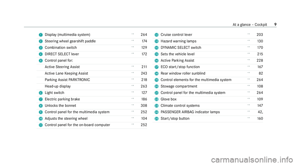
Displ ay(multimedia sy stem) →
264
2 Steering wheel gearshift paddle →
174
3 Combination swit ch →
12 9
4 DIRECT SELECT le ver →
172
5 Control panel for:
Ac tive Steering Assist →
211
Ac tive Lane Keeping Assist →
24 3
Pa rking Assist PARKTRONIC →
218
Head-up display →
263
6 Light switch →
127
7 Electric pa rking brake →
186
8 Unloc ksthe bonn et →
308
9 Control panel forth e multimedia sy stem →
252
A Adjusts thesteering wheel →
104
B Control panel forth e on-board computer →
252 C
Cruise control le ver →
203
D Hazard warning lamps →
13 0
E DYNA MIC SELECT switch →
17 0
F Sets theve hicle le vel →
215
G Active Parking Assist →
228
H ECO start/ stop function →
167
I Rear wind ow roller sunblind →
82
J Cont rol elements forth e multimedia sy stem →
264
K Stow age compartment →
108
L Control panel forth e multimedia sy stem →
264
M Glovebox →
109
N Climate cont rol sy stems →
147
O PASSENGER AIRB AGindicator lamps →
42,
P Start/ stop button →
16 0 At
aglance – Cockpit 9
Page 49 of 497
Fu
nction of PRE-SAFE ®
PLUS (anticipatory
occupant pr otection plus) PRE-
SAFE®
PLUS can de tect cer tain impacts,
particular lyan imminent rear impact, and take
pre-em ptive measures toprotect theve hicle
occupants. These measures cannot necessarily
pr eve nt an imminent impact.
PRE-SAFE ®
PLUS can implement thefo llowing
measures independently of each other:
R Tightening the seat belts on the driver's seat
and front passenger seat.
R Activating there ar hazard warning lights at a
higher flashing frequenc y.
R Increasing brake pressure when theve hicle
is stationar y.This brake application is cancel‐
led automatically when theve hicle pulls
aw ay.
If an accident did not occur, the pre-em ptive
measures that we retake n are reve rsed. Sy
stem limitations
The sy stem will not initiate any action in thefo l‐
lowing situations:
R when reve rsing
or
R when theve hicle is towing a trailer and there
is a risk of a rear impact
The sy stem will not initiate any braking applica‐
tion in thefo llowing situations:
R whilst driving
or
R when entering or exiting a parking space
while using Active Parking Assist Information on PRE-
SAFE®
Impulse Side If an imminent side impact is de
tected, PRE-
SA FE®
Impulse Side can pre-emptively mo vethe
front-seat vehicle occupant's upper body
to wa rdsth e cent reoftheve hicle. It does this by
ra pidly inflating an air cushion in the outer seat
side bols ter of the seat backrest on the side on
which the impact is anticipated. This increases th
e dis tance between the door and theve hicle
occupant.
If PRE-SAFE ®
Impulse Side has been deplo yed or
is faulty, thePRE-SAFE impulse side inoperative
See Owner's Manual display message is shown
(→ page 382). Children in
theve hicle Note
s onthe safe transportation of children &
WARNING Risk of accident and inju ry
due tochildren left unat tended in the
ve hicle
If yo u lea vechildren unat tended in theve hi‐
cle, they may be able toset theve hicle in
motion, forex ample by:
R Releasing the parking brake.
R Shifting the automatic transmission out
of park position jor shifting the manual
transmission into neutral.
R Starting the engine. 46
Occupant saf ety
Page 172 of 497
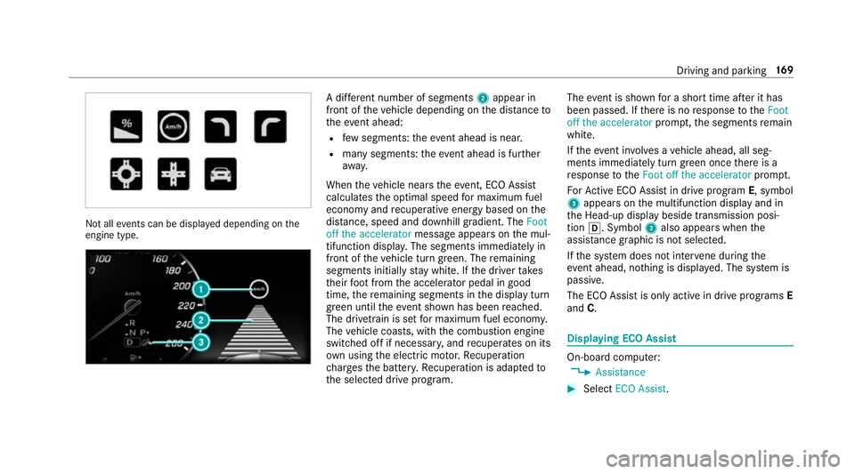
Not all
events can be displa yed depending on the
engine type. A dif
fere nt number of segments 2appear in
front of theve hicle depending on the dis tance to
th eeve nt ahead:
R few segments: theeve nt ahead is nea r.
R many segments: theev ent ahead is fur ther
aw ay.
When theve hicle nears theeve nt, ECO Assi st
calculates the optimal speed for maximum fuel
economy and recuperati veenergy based on the
dis tance, speed and downhill gradient. The Foot
off the accelerator messageappears on the mul‐
tifunction displa y.The segments immediately in
front of theve hicle turn green. The remaining
segments initially stay white. If the driver takes
th eir foot from the accelerator pedal in good
time, there maining segments in the display turn
green until theev ent shown has been reached.
The driv etra in is set for maximum fuel econom y.
The vehicle coasts, with the combustion engine
switched off if necessar y,and recuperates on its
ow n using the electric mo tor.Re cuperation
ch arge sth e batter y.Re cuperation is adap tedto
th e selected drive program. The
event is shown for a short time af ter it has
been passed. If there is no response totheFoot
off the accelerator prompt,th e segments remain
white.
If th eeve nt in volves a vehicle ahead, all seg‐
ments immediately turn green once there is a
re sponse totheFoot off the accelerator prompt.
Fo rAc tive ECO Assi stin drive prog ram E, symbol
3 appears on the multifunction display and in
th e Head-up display beside transmission posi‐
tion h. Symbol 3also appears when the
assis tance graphic is not selected.
If th e sy stem does not inter vene du ring the
eve nt ahead, no thing is displa yed. The sy stem is
passive.
The ECO Assist is only active in drive prog rams E
and C. Displaying ECO Assist
On-board computer:
, Assistance #
Select ECO Assist . Driving and parking
16 9
Page 174 of 497
*
NO
TEDama getothe transmission by
shifting toreve rsege ar k while the
ve hicle is in motion #
Only shift into reve rsege ar k when
th eve hicle is stationar y. k
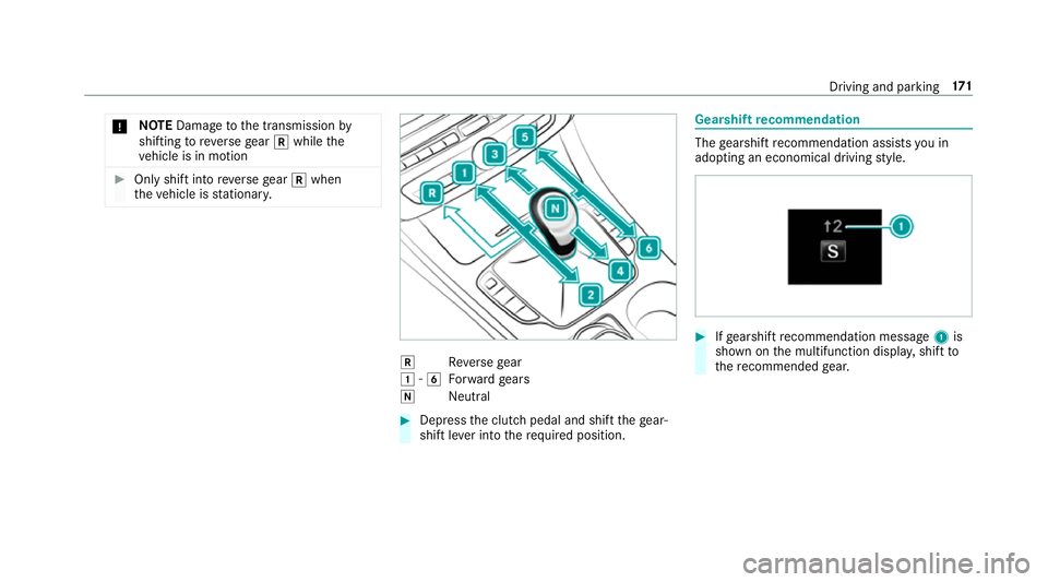
Reversege ar
1 -6
Forw ard gears
i Neutral #
Dep ress the clutch pedal and shift thege ar‐
shift le ver into therequ ired position. Gearshift
recommendation The
gearshift recommendation assists you in
adopting an economical driving style. #
Ifge arshift recommendation message 1is
shown on the multifunction displa y,shift to
th ere commended gear. Driving and parking
171
Page 178 of 497
Using kickdown
Mercedes-AMG
vehicles: observeth e no tes in
th e Supplement. Otherwise, you may failto rec‐
ognise dangers. #
Maximum acceleration: depress the accel‐
erator pedal be yond the pressure point.
During kickdown, you cannot shift gears using
th esteering wheel gearshift paddles. The auto‐
matic transmission shifts up tothe next gear
when the maximum engine speed is reached to
pr otect the engine from overrev ving. #
Ease off the accelera tor pedal once the
desired speed is reached. Glide mode function
Mercedes
-AMG vehicles: observeth e no tes in
th e Supplement. Otherwise, you may failto rec‐
ognise dangers.
Wi th an anticipatory driving style, glide mode
helps youto reduce fuel consum ption. Glide mode is
characterised bythefo llowing:
R the combustion engine is disconnected from
th e drive train and theve hicle continues to
ro ll in neut ral.
R the transmission position his displa yed in
green in the multifunction displa y.
R Vehicles with a 48 V electrical sy stem
(EQ-Boost tech nology): the combustion
engine is switched off depending on the driv‐
ing situation. All of theve hicle functions
re main active.
Glide mode is activated if thefo llowing condi‐
tions are me t:
R drive program Eis selected.
R the speed is within a suitable range.
R the course of thero ad is suitable, e.g. no
st eep uphill or downhill gradients or tight
bends.
R there is no trailer coupled tothe ball coupling
of the trailer tow hit ch, and no bicycle rack
fi tted.
R you are no lon ger depressing the accelerator
or brake pedal. %
Glide mode can also be activated if you ha ve
selected the "Eco" setting forth e drive
(engine management) when in drive program
I.
Glide mode is deactivated again if one of the
conditions is no longer met.
Ve hicles with Driving Assistance Package,
Ac tive Di stance Assist DISTRO NIC orActive
Brake Assi st:Glide mode is also deacti vated
depending on the traf fic situation and theve hi‐
cle then switches to overru n mode. This fur ther
re duces fuel consum ption.
Glide mode can also be pr evented bythefo llow‐
ing parame ters:
R uphill gradient
R downhill gradient
R temp erature
R height
R speed
R obstruction de tection
R ope rating conditions of the engine Driving and parking
175
Page 190 of 497
function is activated via
the Mercedes
connect me web app. Ve
hicles with manual transmission:
When theve hicle comes toast andstill, the elec‐
tric parking brake is applied if one of thefo llow‐
ing conditions is fulfilled:
R The engine is switched off.
R The seat belt tongue is not inser ted in the
seat belt buckle of the driver's seat and the
driver's door is opened.
The elect ric pa rking brake is also applied while
th eve hicle kept stationary bythe HOLD function
if one of thefo llowing conditions is fulfilled:
R The engine is switched off.
R The seat belt tongue is not inser ted in the
seat belt buckle of the driver's seat and the
driver's door is opened.
R There is a sy stem malfunction.
R The po wer supply is insuf ficient.
R The vehicle is stationary for a lengt hyperiod. When
the electric parking brake is applied,
th e! indicator lamp lights up in the instru‐
ment clus ter.
The electric parking brake is not automatically
applied if the engine is switched off bythe ECO
st art/ stop function.
% Toprev ent application: pull the handle of the
electric parking brake.
Ve hicles with automatic transmission:
The electric parking brake is applied if the trans‐
mission is in position jand one of thefo llow‐
ing conditions is fulfilled:
R The engine is switched off.
R The seat belt tongue is not inser ted in the
seat belt buckle of the driver's seat and the
driver's door is opened.
% Toprev ent application: pull the handle of the
electric parking brake.
In thefo llowing situations, the electric parking
brake is also engaged:
R The Active Dis tance Assi stant DI STRO NIC is
bringing theve hicle toast andstill. R
The HOLD function is keeping theve hicle sta‐
tionar y.
R Active Parking Assist is keeping theve hicle
st ationar y.
This is only the case if one of thefo llowing con‐
ditions is also fulfilled:
R The engine is switched off.
R The seat belt tongue is not inser ted in the
seat belt buckle of the driver's seat and the
driver's door is opened.
R There is a sy stem malfunction.
R The po wer supply is insuf ficient.
R The vehicle is stationary for a lengt hyperiod.
When the electric parking brake is applied,
th e! indicator lamp lights up in the instru‐
ment clus ter.
The electric parking brake is not automatically
applied if the engine is switched off bythe ECO
st art/ stop function.
Electric parking brake function (releasing
automatically)
Ve hicles with manual transmission: Driving and parking
187
Page 193 of 497
St
andby mode is characterised bythefo llowing:
R thest ar ter battery is preser ved.
R the maximum period out of use is displa yed
in the multimedia sy stem displa y.
R functions such as interior pr otection or tow-
aw ay protection are not available.
R the connection toonline services is inter rup‐
te d.
If th efo llowing conditions are fulfilled, standby
mode can be activated or deactivated using the
multimedia sy stem:
R the engine is switched off.
R the ignition is switched on.
Exceeding theve hicle's displa yed period out of
use may cause incon venience, i.e. it cannot be
guaranteed that thest ar ter battery will reliably
st art the engine.
The star ter battery must be charge dfirs t in the
fo llowing situations:
R theve hicle's period out of use must be
ex tended. R
theBattery charge insufficient for standby
mode message appears in the multimedia
sy stem displa y.
% Standby mode is automatically deactivated
when the ignition is switched on.
Ac tivating or deactivating standby mode
Ve hicles without a 48 V electrical sy stem
(EQ Boost technology):
Multimedia sy stem:
, Vehicle .
Vehicle settings .
Standby
mode #
Activate or deacti vate the function.
When you activate the function, a prom pt
appears. #
Select Yes.
St andby mode is activated. Driving and driving saf
ety sy stems Driving sy
stems and your responsibility Yo
ur vehicle is equipped with driving sy stems
which assist you in driving, parking and manoeu‐ vring
theve hicle. The driving sy stems are tools
and do not relie ve you of your responsibility. Pay
attention tothe tra ffic conditions at all times
and inter vene when necessa ry. Be aware of the
limitations rega rding the safe use of these sys‐
te ms. Fu
nction of thera dar senso rs Some driving and driving sa
fety sy stems use
ra dar sensors tomonitor the area in front of,
behind or next totheve hicle (depending on the
ve hicle's equipment).
Depending on theve hicle's equipment, thera dar
sensors are integrated behind the bumpers
and/or behind thera diator grille. Keep these
parts free of dirt, ice and slush (→ page317).
The sensors must not be co vered, forex ample
by bicycle rack s, ove rhanging loads or radar-
re flecting sticke rs.Fo llowing an impact and in
th eeve nt of associated dama ge, which may not
be visible, tothe bumpers or radiator grille, ha ve
th e function of thera dar sensors checked at a
qu alified specialist workshop. The driver assis‐
ta nce sy stem may no longer workproperly. 19 0
Driving and pa rking
Page 194 of 497
Overview of driving sy
stems and driving
saf ety sy stems In
this section, you will find information about
th efo llowing driving sy stems and driving saf ety
sy stems:
R 360° Camera (→ page 223)
R ABS (A nti-lock Braking System) (→ page191)
R Active Dis tance Assi stDISTRONIC
(→ page 205)
R Adaptive brake lights (→ page 201)
R AIR BODY CONTROL (→ page213)
R Active Brake Assi st (→page 196)
R Active Lane Keeping Assist (→ page241)
R ATTENTION ASSIST (→ page 237)
R BAS (Brak eAssist System) (→ page191)
R DYNA MIC BODY CONT ROL (→ page 213)
R EBD ( Electronic Brakeforc eDistribution)
(→ page 196)
R ESP ®
(E lectronic Stability Program)
(→ page 192)
R Hill Start Assist R
HOLD function (→ page212)
R STEER CONTROL (→ page 196)
R Active Steering Assist (→ page210)
R Limi ter (→ page 202)
R Active Parking Assist (→ page 226)
R Parking Assist PARKTRONIC (→ page216)
R Reversing camera (→ page 220)
R Cruise control (→ page 201)
R Blind Spot Assist and Active Blind Spot Assi st
( → page 239) Fu
nctions of ABS (anti-lock braking sy stem) ABS
regulates the brake pressure in critical driv‐
ing situations:
R During braking, e.g. at maximum full-s top
braking or insuf ficient traction of the tyres,
th e wheels are pr evented from blocking.
R Vehicle steerability while braking is ensured.
If ABS inter venes when braking, you will feel a
pulsing in the brake pedal. The pulsating brake
pedal can be an indication of hazardous road conditions and can ser
veas a reminder totake
ex tra care while driving.
Sy stem limitations
R ABS is active from speeds of appr ox.
8 km/h.
R ABS may be impai red or may not function if a
malfunction has occur red and theye l‐
low ! ABSwarning lamp lights up contin‐
uously in the instrument clus ter af terthe
engine is star ted. Fu
nction of BAS (Brake Assist Sy stem) &
WARNING Risk of an accident caused by
a malfunction in BAS (Brake Assi stSys‐
te m)
If BA S is malfunctioning, the braking dis tance
in an emergency braking situation is
increased. #
Dep ress the brake pedal with full force
in emer gency braking situations. ABS
pr eve nts the wheels from locking. Driving and parking
191
Page 198 of 497
Ac
tivating/deactivating ESP ®
(Electronic Sta‐
bility Prog ram) Multimedia sy
stem:
, Vehicle .
Assistance .
Electronic Sta-
bility Program
Mercedes‑AMG vehicles: always obser vethe
no tes in the Supplement. Otherwise, you may
fa ilto recognise dangers. #
Activate or deacti vate the function.
ESP ®
is deactivated if theå ESP®
OFF warn‐
ing lamp lights up continuously in the instrument
clus ter.
Obser vethe information on warning lamps and
display messages which may be shown in the
instrument clus ter. Fu
nctions of ESP ®
Crosswind Assist ESP
®
Crosswind Assist de tects sudden gu sts of
side wind and helps the driver tokeep theve hi‐
cle in the lane:
R ESP ®
Crosswind Assist is active at vehicle
speeds between 80 km/h and 200 km/h
when driving stra ight ahead or cornering
slightly.
R The vehicle is stabilised bymeans of individ‐
ual brake application on one side. Fu
nctions of ESP ®
trailer stabilisation &
WARNING Risk of accident in poor road
and weather conditions
In poor road and weather conditions, the
trailer stabilisation cannot pr event lu rching of
th eve hicle/trailer combination. Trailers with
a high centre of gr avity may tip over before
ESP ®
de tects this. #
Alw ays adapt your driving style to suit
th e cur rent road and weather condi‐
tions. When driving with a trailer, ESP
®
can stabilise
yo ur vehicle if the trailer begins toswer vefrom
side toside:
R ESP ®
trailer stabilisation is active abo ve
speeds of 65 km/h.
R Slight swerving is reduced bymeans of a tar‐
ge ted, individual brake application on one
side.
R Intheeve nt of se vere swerving, the engine
output is also reduced and all wheels are
braked.
ESP ®
trailer stabilisation may be impaired or
may not function if:
R The trailer is not connec ted cor rectly or is
not de tected prope rly by theve hicle. Driving and parking
19 5