MERCEDES-BENZ E-Class WAGON 2016 W213 Owner's Manual
Manufacturer: MERCEDES-BENZ, Model Year: 2016, Model line: E-Class WAGON, Model: MERCEDES-BENZ E-Class WAGON 2016 W213Pages: 350, PDF Size: 6.71 MB
Page 251 of 350
the hinges of the EASY-PACK folding lug-
gage-compartment floor.
!Vehicles with a B&O sound system: do not
remove the EASY-PACK folding floor.
Removing the EASY-PACK folding floor will
cause the cable set or the amplifier to be
damaged because the amplifier module is
screwed to the underside of the EASY-
PACK folding floor.
Opening and closing the folding cargo
compartment floor
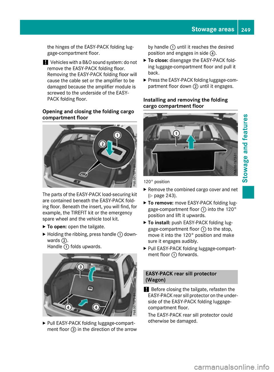
The parts of the EASY-PACK load-securing kit are contained beneath the EASY-PACK fold-
ing floor. Beneath the insert, you will find, for
example, the TIREFIT kit or the emergency
spare wheel and the vehicle tool kit.
XTo open: open the tailgate.
XHolding the ribbing, press handle :down-
wards ;.
Handle :folds upwards.
XPull EASY-PACK folding luggage-compart-
ment floor =in the direction of the arrow by handle
:until it reaches the desired
position and engages in side ?.
XTo close:disengage the EASY-PACK fold-
ing luggage-compartment floor and pull it
back.
XPress the EASY-PACK folding luggage-com-
partment floor down ;until it engages.
Installing and removing the folding
cargo compartment floor
120° position
XRemove the combined cargo cover and net
(
Ypage 243).
XTo remove: move EASY-PACK folding lug-
gage-compartment floor :into the 120°
position and lift it upwards.
XTo install: push EASY-PACK folding lug-
gage-compartment floor :to the stop,
move it into the 120° position and make
sure it engages audibly.
XPull EASY-PACK folding luggage-compart-
ment floor :forwards.
EASY-PACK rear sill protector
(Wagon)
!
Before closing the tailgate, refasten the
EASY-PACK rear sill protector on the under-
side of the EASY-PACK folding luggage-
compartment floor.
The EASY-PACK rear sill protector could
otherwise be damaged.
Stowag earea s249
Stowag ean d features
Z
Page 252 of 350
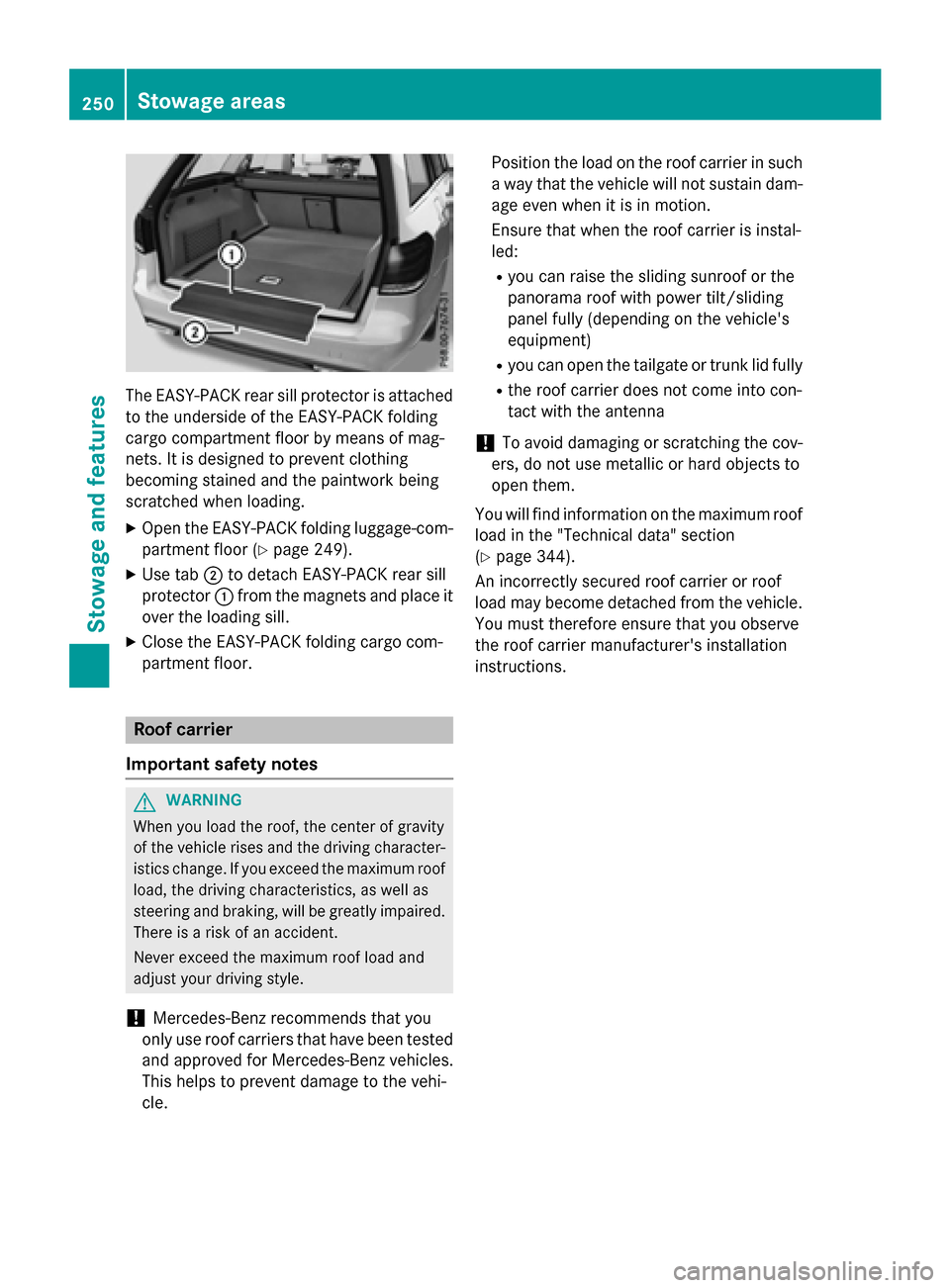
The EASY-PACK rear sill protector is attached
to the underside of the EASY-PACK folding
cargo compartment floor by means of mag-
nets. It is designed to prevent clothing
becoming stained and the paintwork being
scratched when loading.
XOpen the EASY-PACK folding luggage-com-
partment floor (
Ypage 249).
XUse tab;to detach EASY-PACK rear sill
protector :from the magnets and place it
over the loading sill.
XClose the EASY-PACK folding cargo com-
partment floor.
Roof carrier
Important safety notes
GWARNING
When you load the roof, the center of gravity
of the vehicle rises and the driving character-
istics change. If you exceed the maximum roof
load, the driving characteristics, as well as
steering and braking, will be greatly impaired.
There is a risk of an accident.
Never exceed the maximum roof load and
adjust your driving style.
!Mercedes-Benz recommends that you
only use roof carriers that have been tested
and approved for Mercedes-Benz vehicles.
This helps to prevent damage to the vehi-
cle. Position the load on the roof carrier in such
a way that the vehicle will not sustain dam-
age even when it is in motion.
Ensure that when the roof carrier is instal-
led:
Ryou can raise the sliding sunroof or the
panorama roof with power tilt/sliding
panel fully (depending on the vehicle's
equipment)
Ryou can open the tailgate or trunk lid fully
Rthe roof carrier does not come into con-
tact with the antenna
!To avoid damaging or scratching the cov-
ers, do not use metallic or hard objects to
open them.
You will find information on the maximum roof
load in the "Technical data" section
(
Ypage 344).
An incorrectly secured roof carrier or roof
load may become detached from the vehicle.
You must therefore ensure that you observe
the roof carrier manufacturer's installation
instructions.
250Stowage areas
Stowage and features
Page 253 of 350

Attaching theroof car rier (Sedan)
Vehicles wit h asteel roo for sliding sunroo f(illus -
tration )
Vehicles wit h apanorama roo fwit hpowe rtilt/slid-
ing panel
XOpen cover s: carefully in th edirection of
th earrow.
XFold cover s: upwards.
XOnly secure th eroo fcarrie rto th eanchor -
age points under cover s:.
XObserv eth emanufacturer' sinstallation
instructions.
Attaching the roof car rier (Wagon)
XSecur eth eroo fcarrie rto th eroo frails .
XObserv eth emanufacturer' sinstallation
instructions.
Features
Infor mation in the Digital Operator's
Manual
In th eDigital Operator' sManual you will fin d
information on th efollowin gtopic s:
RCup holder
RBottle holder
RRoller sunblinds on th erear side windows
RRear window roller sunblin d(Sedan )
RAshtray
RCigarette lighte r
R12V sockets
R115 V socke t
Sun visors
Overview
GWARNIN G
If th emirror cover of th evanit ymirror is folded
up when th evehicl eis in motion ,you could be
blinded by inciden tlight. There is aris kof an
accident.
Always keep th emirror cover folded down
while driving.
:Mirror ligh t
;Additional sunvisor
=Bracket
?Retaining clip, e.g. for acar park ticket
AVanit ymirror
BMirror cover
Features251
Stowage and features
Z
Page 254 of 350
Information in the Digital Operator's
Manual
Inthe Digital Operator's Manual you willfind
information on the following topics:
RVanit y mirror inthe sun visor
RGlare from the side
mbrace
Information in the Digital Operator's
Manual
In the Digital Operator's Manual you willfind
information on the following topics:
RDownloading destinations inCOMAND
RSe arch & Send
RVehicle remote opening
RVehicle remote closing
RStolen vehicle recovery service
RVehicle remote malfunction diagnosis
RDownloading routes
RSp eed alert
RGeo fencing
RTriggering the vehicle alarm
iThe mbrace system isonly availab le inthe
USA.
General notes
The mbrace system is only availablein the
USA.
You must have a license agreement to acti-
vate the mbrace service. Make sure that your system isactivated and operational. To log in,
press the ïMBInfo call button. Ifany of
the steps mentioned are not carried out, the
system may not be activated.
If you have questions about the activation,
contact one of the fol lowing telephone hot-
lin es:
Mercedes-Benz Customer Assistance Center
at 1-800-FOR-M ERCedes (1-800-367-6372)
or 1-866-990-9007 Sh
ort lyafter successfully registering with the
mbrace service, a user IDand password will
be sent to you bymail. You can use th ispass-
word to log onto the mbrace area under "Own-
ers Onlin e" athttp://www.mbusa.com .
The system isavailab leif:
Rit has been activated and isoperational
Rthe corresponding mob ilephone network is
availab lefor transmitting data to the Cus-
tomer Center
Ra servic e subscr iption isavailab le
Rthe starter battery issufficiently charged
Determining the location of the vehicle on a
map isonly possible if:
RGPS reception isavailable.
Rthe vehicle posit ion canbeforwarded to
the Customer Assistance Center.
The mbrace system
To adjust the volume during a call, proceed as
follows:
XPress the WorX button on the mul-
tifunction steering wheel.
or
XUse the COMAND/A udio 20 volume con-
trol.
The system offers various servic es, e.g.:
RAutomaticand manual emergency call
RRoadside Assistance call
RMB Info call
You can find information and a description of
all availab lefeatures under "Owners Online"
at http:/ /www.mbusa.com.
System self-test
After you have switched on the ignit ion, the
system carries out a self-diagnosis.
252Features
Stowage and features
Page 255 of 350
A malfunction in the system has been detec-
ted if one of the following occurs:
RThe indicator lamp in the SOS button doesnot come on during the system self-test.
RThe indicator lamp in the FRoadside
Assistance button does not light up during
self-diagnosis of the system.
RThe indicator lamp in the ïMB Info call
button does not light up during self-diag-
nosis of the system.
RThe indicator lamp in one or more of the
following buttons continues to light up red
after the system self-diagnosis:
-SOS button
-F Roadside Assistance call button
-ïMB Info call button
RTheInoperativeor the Service Not
Activatedmessage appears in the multi-
function display after the system self-diag-
nosis.
If a malfunction is indicated as outlined
above, the system may not operate as expec-
ted. In the event of an emergency, help will
have to be summoned by other means.
Have the system checked at the nearest
authorized Mercedes-Benz Center or contact the following service hotlines:
Mercedes-Benz Customer Assistance Center
at 1-800-FOR-MERCedes (1-800-367-6372)
or 1-866-990-9007
Emergency call
Important safety notes
GWARNING
It can be dangerous to remain in the vehicle,
even if you have pressed the SOS button in an emergency if:
Ryou see smoke inside or outside of the vehi-
cle, e.g. if there is a fire after an accident
Rthe vehicle is on a dangerous section of
road
Rthe vehicle is not visible or cannot easily beseen by other road users, particularly when
dark or in poor visibility conditions
There is a risk of an accident and injury.
Leave the vehicle immediately in this or simi-
lar situations as soon as it is safe to do so.
Move to a safe location along with other vehi-
cle occupants. In such situations, secure the
vehicle in accordance with national regula-
tions, e. g. with a warning triangle.
General notes
Observe the notes on system activation
(
Ypage 252).
An emergency call is dialed automatically if an
air bag or Emergency Tensioning Device is
triggered. You cannot end an automatically
triggered emergency call yourself.
An emergency call can also be initiated man-
ually.
As soon as the emergency call has been ini-
tiated, the indicator lamp in the SOS button
flashes. The Connecting Call
message
appears in the multifunction display.
The audio output is muted.
Once the connection has been made, the
Call Connected
message appears in the
multifunction display.
Features253
Stowag ean d features
Z
Page 256 of 350
All important information on the emergency is
transmitted, for example:
Rcurrent location of the vehicle (as deter-
mined by the GPS system)
Rvehicle identification number
Rinformation on the severity of the accident
Shortly after the emergency call has been ini- tiated, a voice connection is automatically
established between the Customer Assis-
tance Center and the vehicle occupants.
RIf the vehicle occupants respond, the
Mercedes-Benz Customer Assistance Cen-
ter attempts to get more information on the
emergency.
RIf there is no response from the vehicle
occupants, an ambulance is immediately
sent to the vehicle.
If no voice connection can be established to
the Mercedes-Benz Customer Assistance
Center, the system has been unable to initiate
an emergency call.
This can occur, for example, if the relevant
mobile phone network is not available. The
indicator lamp in the SOS button flashes con- tinuously.
The Call Failed
message appears in the
multifunction display and must be confirmed.
In this case, summon assistance by other
means.
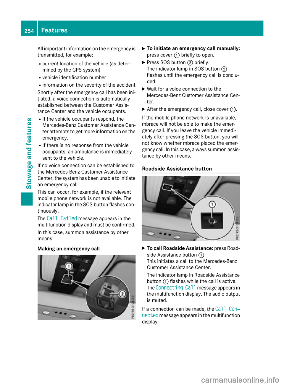
Making an emergency call
XTo initiate an emergency call manually:
press cover :briefly to open.
XPress SOS button ;briefly.
The indicator lamp in SOS button ;
flashes until the emergency call is conclu-
ded.
XWait for a voice connection to the
Mercedes-Benz Customer Assistance Cen-
ter.
XAfter the emergency call, close cover :.
If the mobile phone network is unavailable,
mbrace will not be able to make the emer-
gency call. If you leave the vehicle immedi-
ately after pressing the SOS button, you will
not know whether mbrace placed the emer-
gency call. In this case, always summon assis-
tance by other means.
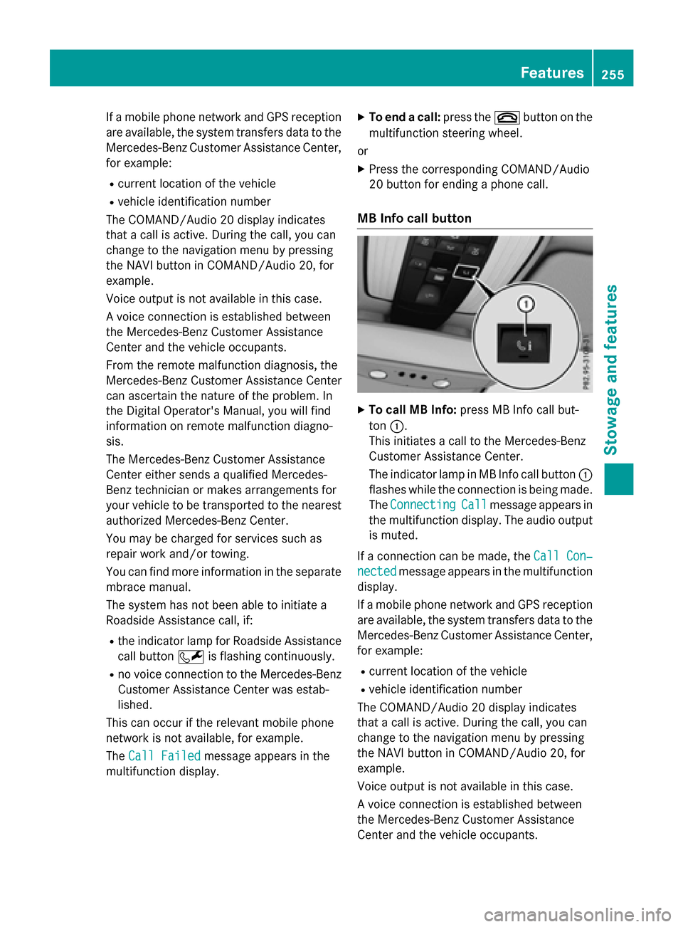
Roadside Assistance button
XTo call Roadside Assistance: press Road-
side Assistance button :.
This initiates a call to the Mercedes-Benz
Customer Assistance Center.
The indicator lamp in Roadside Assistance
button :flashes while the call is active.
The Connecting
Callmessage appears in
the multifunction display. The audio output is muted.
If a connection can be made, the Call Con‐
nectedmessage appears in the multifunction
display.
254Features
Stowag ean d features
Page 257 of 350
If a mobile phone network and GPS reception
are available, the system transfers data to the
Mercedes-Benz Customer Assistance Center,
for example:
Rcurrent location of the vehicle
Rvehicle identification number
The COMAND/Audio 20 display indicates
that a call is active. During the call, you can
change to the navigation menu by pressing
the NAVI button in COMAND/Audio 20, for
example.
Voice output is not available in this case.
A voice connection is established between
the Mercedes-Benz Customer Assistance
Center and the vehicle occupants.
From the remote malfunction diagnosis, the
Mercedes-Benz Customer Assistance Center
can ascertain the nature of the problem. In
the Digital Operator's Manual, you will find
information on remote malfunction diagno-
sis.
The Mercedes-Benz Customer Assistance
Center either sends a qualified Mercedes-
Benz technician or makes arrangements for
your vehicle to be transported to the nearest
authorized Mercedes-Benz Center.
You may be charged for services such as
repair work and/or towing.
You can find more information in the separate
mbrace manual.
The system has not been able to initiate a
Roadside Assistance call, if:
Rthe indicator lamp for Roadside Assistance
call button Fis flashing continuously.
Rno voice connection to the Mercedes-Benz
Customer Assistance Center was estab-
lished.
This can occur if the relevant mobile phone
network is not available, for example.
The Call Failed
message appears in the
multifunction display.
XTo end a call: press the~button on the
multifunction steering wheel.
or
XPress the corresponding COMAND/Audio
20 button for ending a phone call.
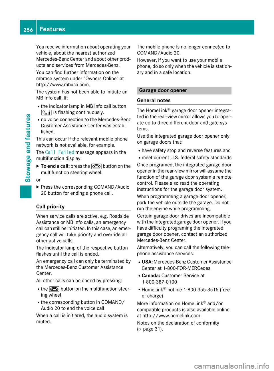
MB Info call button
XTo call MB Info: press MB Info call but-
ton :.
This initiates a call to the Mercedes-Benz
Customer Assistance Center.
The indicator lamp in MB Info call button :
flashes while the connection is being made.
The Connecting
Callmessage appears in
the multifunction display. The audio output
is muted.
If a connection can be made, the Call Con‐
nectedmessage appears in the multifunction
display.
If a mobile phone network and GPS reception
are available, the system transfers data to the
Mercedes-Benz Customer Assistance Center,
for example:
Rcurrent location of the vehicle
Rvehicle identification number
The COMAND/Audio 20 display indicates
that a call is active. During the call, you can
change to the navigation menu by pressing
the NAVI button in COMAND/Audio 20, for
example.
Voice output is not available in this case.
A voice connection is established between
the Mercedes-Benz Customer Assistance
Center and the vehicle occupants.
Features255
Stowage and features
Z
Page 258 of 350
You receive information about operating your
vehicle, about the nearest authorized
Mercedes-Benz Center and about other prod-
ucts and services from Mercedes-Benz.
You can find further information on the
mbrace system under "Owners Online" at
http://www.mbusa.com.
The system has not been able to initiate an
MB Info call, if:
Rthe indicator lamp in MB Info call button
ïis flashing continuously.
Rno voice connection to the Mercedes-Benz
Customer Assistance Center was estab-
lished.
This can occur if the relevant mobile phone
network is not available, for example.
The Call Failed
message appears in the
multifunction display.
XTo end a call: press the~button on the
multifunction steering wheel.
or
XPress the corresponding COMAND/Audio
20 button for ending a phone call.
Call priority
When service calls are active, e.g. Roadside
Assistance or MB Info calls, an emergency
call can still be initiated. In this case, an emer-
gency call will take priority and override all
other active calls.
The indicator lamp of the respective button
flashes until the call is ended.
An emergency call can only be terminated by the Mercedes-Benz Customer Assistance
Center.
All other calls can be ended by pressing:
Rthe ~ button on the multifunction steer-
ing wheel
Rthe corresponding button in COMAND/
Audio 20 to end the voice call
When a call is initiated, the audio system is
muted. The mobile phone is no longer connected to
COMAND/Audio 20.
However, if you want to use your mobile
phone, do so only when the vehicle is station-
ary and in a safe location.
Garage door opener
General notes
The HomeLink®garage door opener integra-
ted in the rear-view mirror allows you to oper-
ate up to three different door and gate sys-
tems.
Use the integrated garage door opener only
on garage doors that:
Rhave safety stop and reverse features and
Rmeet current U.S. federal safety standards
Once programed, the integrated garage door
opener in the rear-view mirror will assume the
function of the garage door system's remote
control. Please also read the operating
instructions for the garage door system.
When programming a garage door opener,
park the vehicle outside the garage. Do not
run the engine while programming.
Certain garage door drives are incompatible
with the integrated garage door opener. If you
have difficulty programing the integrated
garage door opener, contact an authorized
Mercedes-Benz Center.
Alternatively, you can call the following tele-
phone assistance services:
RUSA: Mercedes-Benz Customer Assistance
Center at 1-800-FOR-MERCedes
RCanada: Customer Service at
1-800-387-0100
RHomeLink®hotline 1-800-355-3515 (free
of charge)
More information on HomeLink
®and/or
compatible products is also available online
at http://www.homelink.com.
Notes on the declaration of conformity
(
Ypage 31).
256Features
Stowage and features
Page 259 of 350
USA: FCC ID: CB2HMIHL4
Canada: IC: 279B-HMIHL4
Important safety notes
GWARNING
When you operate or program the garage door
with the integrated garage door opener, per-
sons in the range of movement of the garage
door can become trapped or struck by the
garage door. There is a risk of injury.
When using the integrated garage door
opener, always make sure that nobody is
within the range of movement of the garage
door.
GWARNING
Combustion engines emit poisonous exhaust
gases such as carbon monoxide. Inhaling
these exhaust gases leads to poisoning. There
is a risk of fatal injury. Therefore never leave
the engine running in enclosed spaces with-
out sufficient ventilation.
Programming
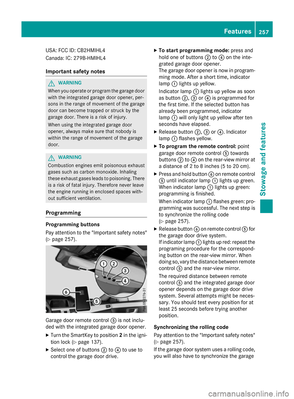
Programming buttons
Pay attention to the "Important safety notes"
(
Ypage 257).
Garage door remote control Ais not inclu-
ded with the integrated garage door opener.
XTurn the SmartKey to position 2in the igni-
tion lock (
Ypage 137).
XSelect one of buttons ;to? to use to
control the garage door drive.
XTo start programming mode: press and
hold one of buttons ;to? on the inte-
grated garage door opener.
The garage door opener is now in program-
ming mode. After a short time, indicator
lamp :lights up yellow.
Indicator lamp :lights up yellow as soon
as button ;,=or? is programmed for
the first time. If the selected button has
already been programmed, indicator
lamp :will only light up yellow after ten
seconds have elapsed.
XRelease button ;,=or?. Indicator
lamp :flashes yellow.
XTo program the remote control: point
garage door remote control Atowards
buttons ;to? on the rear-view mirror at
a distance of 2 to 8 inches (5 to 20 cm).
XPress and hold button Bon remote control
A until indicator lamp :lights up green.
When indicator lamp :lights up green:
programming is finished.
When indicator lamp :flashes green: pro-
gramming was successful. The next step is
to synchronize the rolling code
(
Ypage 257).
XRelease button Bon remote control Afor
the garage door drive system.
If indicator lamp :lights up red: repeat the
programing procedure for the correspond-
ing button on the rear-view mirror. When
doing so, vary the distance between remote
control Aand the rear-view mirror.
The required distance between remote
control Aand the integrated garage door
opener depends on the garage door drive
system. Several attempts might be neces-
sary. You should test every position for at
least 25 seconds before trying another
position.
Synchronizing the rolling code
Pay attention to the "Important safety notes"
(
Ypage 257).
If the garage door system uses a rolling code,
you will also have to synchronize the garage
Features257
Stowage and features
Z
Page 260 of 350
door system with the integrated garage door
opener in the rear-view mirror. To do this you
will need to use the programming button on
the door drive control panel. The program-
ming button may be positioned in different
places depending on the manufacturer. It is
usually located on the door drive unit on the
garage ceiling.
Familiarize yourself with the garage door
drive operating instructions, e.g. under "Pro-
gramming of additional remote controls",
before carrying out the following steps.
Your vehicle must be within reach of the
garage door or gate opener drive. Make sure
that neither your vehicle nor any persons/
objects are present within the sweep of the
door or gate.
XTurn the SmartKey to position2in the igni-
tion lock (
Ypage 137).
XGet out of the vehicle.
XPress the programming button on the door drive unit.
Usually, you now have 30 seconds to ini-
tiate the next step.
XGet into the vehicle.
XPress previously programmed button ;,
= or? on the integrated garage door
opener until the door closes.
The rolling code synchronization is then
complete.
Notes on programming the remote con-
trol
Canadian radio frequency laws require a
"break" (or interruption) of the transmission
signals after broadcasting for a few seconds. Therefore, these signals may not last long
enough for the integrated garage door
opener. The signal is not recognized during
programming. Comparable with Canadian
law, some U.S. garage door openers also fea-
ture a "break". Proceed as follows:
Rif you live in Canada
Rif you have difficulties programming the
garage door opener (regardless of where
you live) when using the programming
steps.
XPress and hold one of buttons
;to? on
the integrated garage door opener.
After a short time, indicator lamp :lights
up yellow.
XRelease the button.
Indicator lamp :flashes yellow.
XPress button Bof garage door remote
control Afor two seconds, then release it
for t
wo seconds.
XPress button Bagain for two seconds.
XRepeat this sequence on button Bof
remote control Auntil indicator lamp :
lights up green.
When indicator lamp :lights up green:
programming is finished.
When indicator lamp :flashes green: pro-
gramming was successful. The next step is
to synchronize the rolling code.
XRelease button Bof remote control Aof
the garage door drive.
If indicator lamp :lights up red: repeat the
programming process for the correspond-
ing button on the rear-view mirror. When
doing so, vary the distance between remote
control Aand the rear-view mirror.
The required distance between remote
control Aand the integrated garage door
opener depends on the garage door drive
system. Several attempts might be neces-
sary. You should test every position for at
least 25 seconds before trying another
position.
258Features
Stowage and features