display MERCEDES-BENZ E-Class WAGON 2016 W213 Owner's Guide
[x] Cancel search | Manufacturer: MERCEDES-BENZ, Model Year: 2016, Model line: E-Class WAGON, Model: MERCEDES-BENZ E-Class WAGON 2016 W213Pages: 350, PDF Size: 6.71 MB
Page 25 of 350
Vehicle dimensions........................... 344
Vehicle emergency locking ................ 96
Vehicle identification number
see VIN
Vehicle identification plate .............. 336
Vehicle level
AIRMATIC ...................................... 166
Vehicle maintenance
see ASSYST PLUS
Vehicle tool kit .................................. 270
Video
see also Digital Operator's Man-
ual .................................................. 214
Video (DVD) ........................................ 190
VIN
Seat ............................................... 336
Type plate ...................................... 336
Voice Control System
see Separate operating instructions
W
Warning and indicator lampsABS ................................................ 205
Brakes ........................................... 204
Check Engine ................................. 202
Coolant .......................................... 209
Distance warning ........................... 210
ESP
®.............................................. 206
ESP®OFF ....................................... 207
Fuel tank ........................................ 202
General notes ................................ 202
Overview .......................................... 38
PASSENGER AIR BAG OFF ............... 49
Reserve fuel ................................... 202
Restraint system ............................ 208
Seat belt ........................................ 202
SPORT handling mode ................... 207
Tire pressure monitor .................... 211
Warranty .............................................. 28
Washer fluid
Display message ............................ 191
Wheel and tire combination
see Tires
Wheel bolt tightening torque ........... 313
Wheel chock ...................................... 310
Wheels
Changing a wheel .......................... 309 Checking ........................................ 289
Cleaning ......................................... 268
Emergency spare wheel ................. 329
General notes ................................ 314
Important safety notes .................. 288
Information on driving .................... 288
Interchanging/changing ................ 309
Mounting a new wheel ................... 313
Mounting a wheel .......................... 309
Removing a wheel .......................... 312
Storing ........................................... 309
Tightening torque ........................... 313
Wheel size/tire size ....................... 314
Window curtain air bag
Operation ......................................... 57
Windows
see Side windows
Windshield
Defrosting ...................................... 133
Windshield washer fluid
see Windshield washer system
Windshield washer system
Adding washer fluid ....................... 266
Important safety notes .................. 343
Windshield wipers
Problem (malfunction) ................... 127
Rear window wiper ........................ 125
Replacing the wiper blades ............ 125
Switching on/off ........................... 125
Winter driving
Important safety notes .................. 290
Slippery road surfaces ................... 155
Snow chains .................................. 291
Winter operation
Radiator cove r ............................... 263
Wi
nter tires
M+S tires ....................................... 290
Wiper blades
Cleaning ......................................... 268
Important safety notes .................. 125
Replacing (rear window) ................ 126
Replacing (windshield) ................... 126
Wooden trim (cleaning instruc-
tions) .................................................. 268
Workshop
see Qualified specialist workshop
Index23
Page 27 of 350
Introduction
Theprinted Operator's Manual provides infor-
mation about the safe operation of your veh i-
cle. The Digital Operator's Manual addition-
ally describe s further functions and equip-
ment installed inyour vehicle. The vehicle
functions and functions of Audio 20 or
COMAND are describe d in the Digital Opera-
tor's Manual. You can call up the Digital Oper-
ator's Manual via Audio 20 or COMAND.
iYou willnot incur any costs when calling
up the Digital Operator's Manual. The Dig-
it al Operator's Manual works without con-
necting to the Internet.
There are three ways to access the topics of
the Digital Operator's Manual:
RVisual search
The visual search allowsyou to explore your
vehicle "virtually". Starting from either the
vehicle exterior view or interior view, you
can access many of the different topics
covered bythe Digital Operator's Manual.
To access the vehicle interior section,
select the "Vehicle interior" view.
RKeyword search
The keyword search allows you to search
for a keyword byentering characters. Fur-
ther information can be found in the Digital
Operator's Manual inthe "Aud io20" or
"COMAND" section under the "Character
entry (telephony)" keyword.
RContents
You can select individ ual sect
ionsinthe
contents.
iThe Digital Operator's Manual is deacti-
vated for safety reasons while driving.
Operation
Calling up the Digital Operator's Man-
ual
XPress the Øbutton inthe center con-
sole.
The overview relating to the vehicle
appears.
XSe lect the "Operator's Manual" menu item
by turning 3or pressing 7the con-
troller.
XConfirm 7the message about the warning
and safety notes.
The basic menu for the Digital Operator's
Manual appears.
Operating the Digital Operator's Man-
ual
General notes
Please observe the information about the
operation of the controller (
Ypage 222).
Content pages
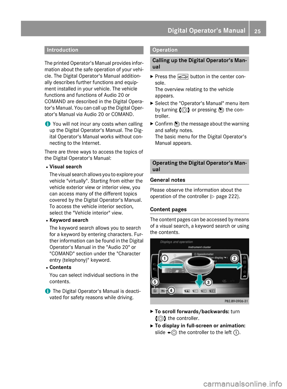
The content pages can beaccessed bymeans
of a visual search, a keyword search or using
the contents.
XTo scroll forwards/backwa rds: turn
3 the controller.
XTo display in full-screen orani mati on:
slide 8 the controller to the left :.
Digital Operator's Manual25
Page 39 of 350
Instrument cluster
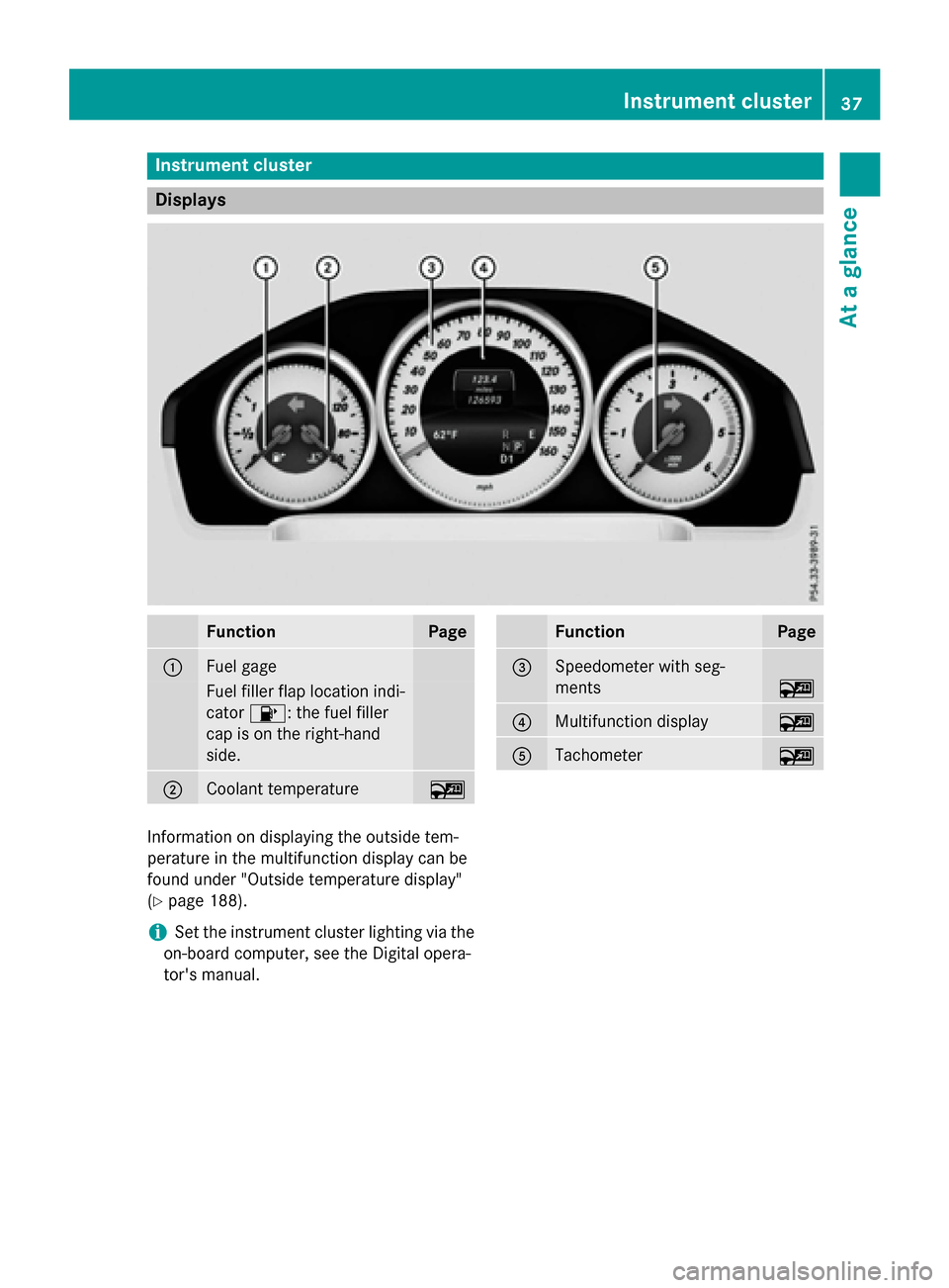
Displays
FunctionPage
:Fuel gage
Fuelfiller flap location ind i-
cator 8: the fuel filler
cap ison the right-hand
side .
;Coolant temperature~
FunctionPage
=Speedometer with seg-
ments
~
?Multifunction display~
ATachometer~
In formation on displaying the outside tem-
perature inthe multifunction display can be
found under "Outside temperature display"
(
Ypage 188).
iSe t the instrument cluster lighting via the
on-board computer, see the Digital opera-
tor's manual.
Instrument cluster37
At a glance
Page 41 of 350
Multifunction steering wheel
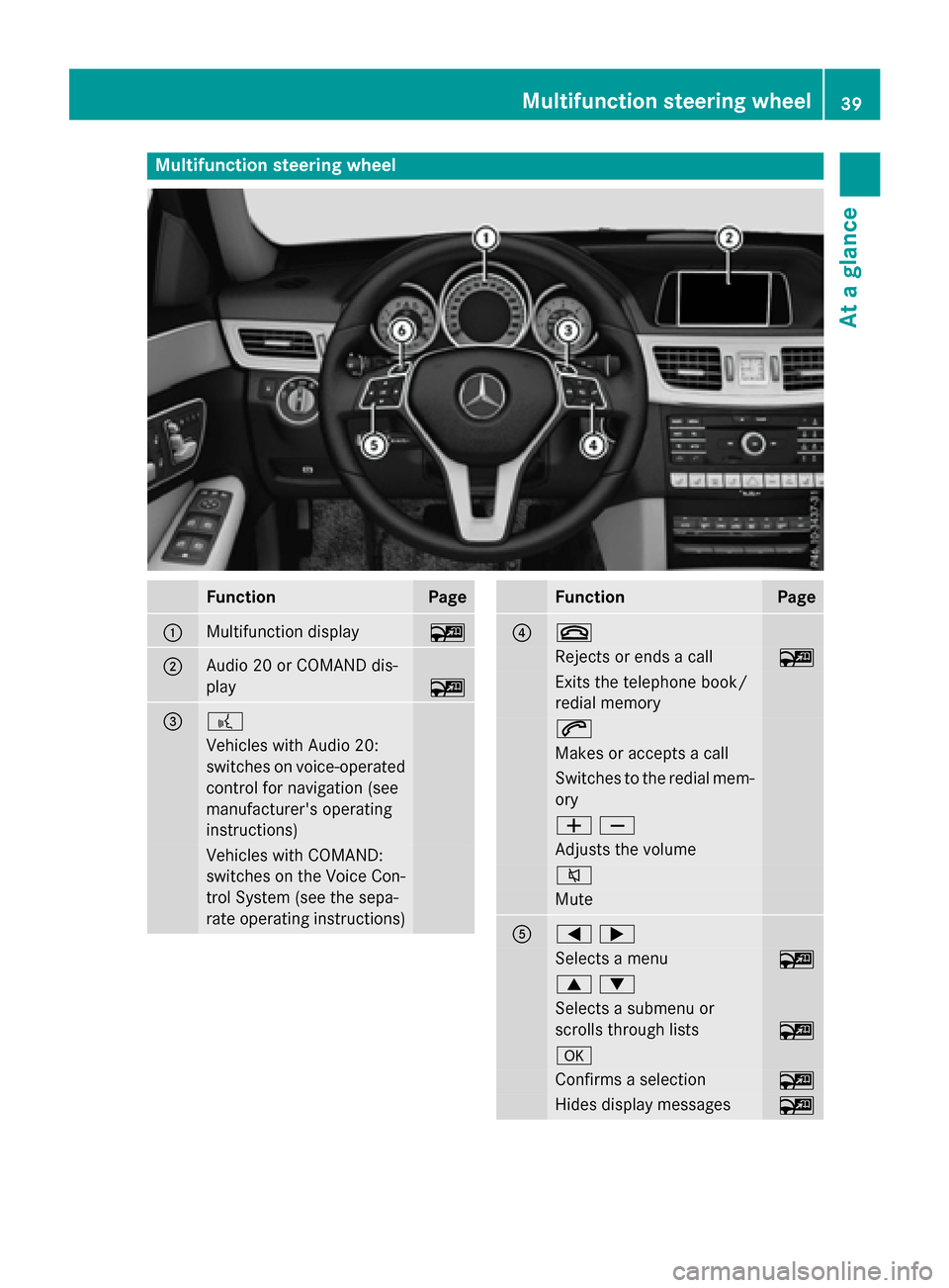
FunctionPage
:Multifunction display~
;Audio 20 or COMAND dis-
play
~
=?
Vehicles with Audio 20:
switches on voice-operated
control for navigation (see
manufacturer's operating
instructions)
Vehicles with COMAND:
switches on the Voice Con-
trol System (see the sepa-
rate operating instructions)
FunctionPage
?~
Rejects or ends a call~
Exits the telephone book/
redial memory
6
Makes or accepts a call
Switches to the redial mem-
ory
WX
Adjusts the volume
8
Mute
A=;
Selects a menu~
9:
Selects a submenu or
scrolls through lists
~
a
Confirms a selection~
Hides display messages~
Multifunction steering wheel39
At a glance
Page 60 of 350
Occupant Classification System
(OCS)
Introduction
The Occupant Classification System (OCS)
categorizes the person in the front-passenger
seat. Depending on that result, the front-
passenger front air bag is either enabled or
deactivated.
The system does not deactivate:
Rthe side impact air bag
Rthe pelvis air bag
Rthe window curtain air bag
Rthe Emergency Tensioning Devices
Prerequisites
To be classified correctly, the front passenger
must sit:
Rwith the seat belt fastened correctly
Rin an almost upright position with their
back against the seat backrest
Rwith their feet resting on the floor, if possi-
ble
If the front passenger does not observe these
conditions, OCS may produce a false classi-
fication, e.g. because the front passenger:
Rtransfers their weight by supporting them-
selves on a vehicle armrest
Rsits in such a way that their weight is raised
from the seat cushion
If it is absolutely necessary to install a child
restraint system on the front-passenger seat,
be sure to observe the correct positioning of
the child restraint system. Never place
objects under or behind the child restraint
system, e.g. cushions. The entire base of the
child restraint system must always rest on the seat cushion of the front-passenger seat. The
backrest of the forward-facing child restraint
system must lie as flat as possible against the
backrest of the front-passenger seat.
The child restraint system must not touch theroof or be subjected to a load by the head
restraint. Adjust the angle of the seat back- rest and the head restraint position accord-
ingly.
Only then can OCS be guaranteed to function
correctly. Always observe the child restraint
system manufacturer's installation instruc-
tions.
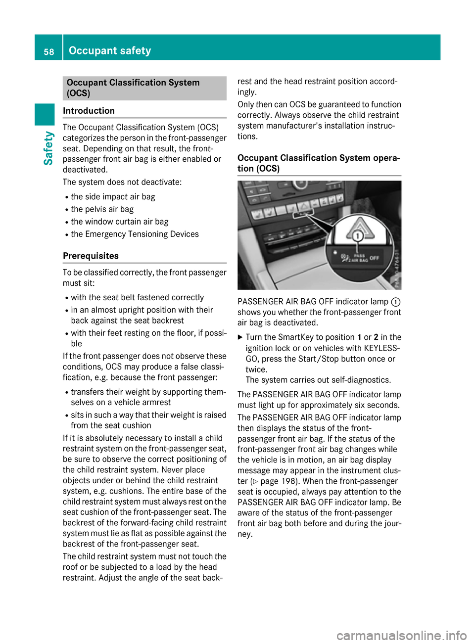
Occupant Classification System opera-
tion (OCS)
PASSENGER AIR BAG OFF indicator lamp :
shows you whether the front-passenger front
air bag is deactivated.
XTurn the SmartKey to position 1or 2in the
ignition lock or on vehicles with KEYLESS-
GO, press the Start/Stop button once or
twice.
The system carries out self-diagnostics.
The PASSENGER AIR BAG OFF indicator lamp
must light up for approximately six seconds.
The PASSENGER AIR BAG OFF indicator lamp
then displays the status of the front-
passenger front air bag. If the status of the
front-passenger front air bag changes while
the vehicle is in motion, an air bag display
message may appear in the instrument clus-
ter (
Ypage 198). When the front-passenger
seat is occupied, always pay attention to the
PASSENGER AIR BAG OFF indicator lamp. Be
aware of the status of the front-passenger
front air bag both before and during the jour-
ney.
58Occupant safety
Safety
Page 63 of 350
When the front-passenger seat is occupied,
always ensure that:
Rthe classification of the person in the front-passenger seat is correct and the front-
passenger front air bag is enabled or disa-
bled in accordance with the person in the
front-passenger seat
Rthe person is seated properly with a cor-
rectly fastened seatbelt
Rthe front-passenger seat has been moved
back as far back as possible
If the PASSENGER AIR BAG OFF indicator
lamp remains lit when it should not, the front-
passenger seat may not be used. Do not
install a child restraint system on the front-
passenger seat. Have the Occupant Classifi-
cation System (OCS) checked and repaired
immediately at a qualified specialist work-
shop.
GWARNING
Objects between the seat surface and the
child restraint system could affect OCS oper- ation. This could result in the front-passenger
air bag not functioning as intended during an
accident. This poses an increased risk of
injury or even fatal injury.
Do not place any objects between the seat
surface and the child restraint system. The
entire base of the child restraint system must
always rest on the seat cushion of the front-
passenger seat. The backrest of the forward-
facing child restraint system must, as far as
possible, be resting on the backrest of the
front-passenger seat. Always comply with the
child restraint system manufacturer's instal-
lation instructions.
After the system self-test, the PASSENGER
AIR BAG OFF indicator lamp displays the sta-
tus of the front-passenger front air bag
(
Ypage 58).
For more information about the OCS, see
"Problems with the Occupant Classification
System" (
Ypage 62).
Occupant safety61
Safety
Z
Page 73 of 350
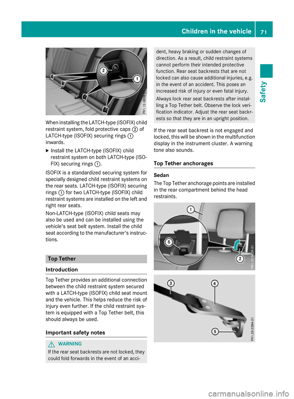
When installing the LATCH-type (ISOFIX) child
restraint system, fold protective caps;of
LATCH-type (ISOFIX) securing rings :
inwards.
XInstall the LATCH-type (ISOFIX) child
restraint system on both LATCH-type (ISO- FIX) securing rings :.
ISOFIX is a standardized securing system for
specially designed child restraint systems on
the rear seats. LATCH-type (ISOFIX) securing
rings :for two LATCH-type (ISOFIX) child
restraint systems are installed on the left and
right rear seats.
Non-LATCH-type (ISOFIX) child seats may
also be used and can be installed using the
vehicle's seat belt system. Install the child
seat according to the manufacturer's instruc-
tions.
Top Tether
Introduction
Top Tether provides an additional connection
between the child restraint system secured
with a LATCH-type (ISOFIX) child seat mount
and the vehicle. This helps reduce the risk of
injury even further. If the child restraint sys-
tem is equipped with a Top Tether belt, this
should always be used.
Important safety notes
GWARNING
If the rear seat backrests are not locked, they
could fold forwards in the event of an acci-
dent, heavy braking or sudden changes of
direction. As a result, child restraint systems
cannot perform their intended protective
function. Rear seat backrests that are not
locked can also cause additional injuries, e.g.
in the event of an accident. This poses an
increased risk of injury or even fatal injury.
Always lock rear seat backrests after instal-
ling a Top Tether belt. Observe the lock veri-
fication indicator. Adjust the rear seat backr-
ests so that they are in an upright position.
If the rear seat backrest is not engaged and
locked, this will be shown in the multifunction
display in the instrument cluster. A warning
tone also sounds.
Top Tether anchorages
Sedan
The Top Tether anchorage points are installed
in the rear compartment behind the head
restraints.
Children in the vehicle71
Safety
Z
Page 80 of 350
pressure will be carried out at the last possi-
ble moment.
When driving at a speed above 20 mph
(30 km/h): if you depress the brake pedal
sharply, BAS PLUS automatically raises the
brake pressure to a value adapted to the traf-
fic situation.
BAS PLUS provides braking assistance in haz-ardous situations with vehicles in front within
a speed range between 4 mph (7 km/h) and
155 mph (250 km/ h).
Up to a speed of approximately 44 mph
(70 km/h), BAS PLUS may react to:
Rstationary objects in the path of your vehi-
cle, e.g. stopped or parked vehicles
Rpedestrians in the path of your vehicle
Robjects crossing your path and that are
recognized in the detection range of the
sensors
iIf BAS PLUS demands particularly high
braking force, preventative passenger pro-
tection measures (PRE-SAFE
®) are activa-
ted simultaneously.
XKeep the brake pedal depressed until the
emergency braking situation is over.
ABS prevents the wheels from locking.
BAS PLUS is deactivated and the brakes func-
tion as usual, if:
Ryou release the brake pedal.
Rthere is no longer a risk of collision.
Rno obstacle is detected in front of your
vehicle.
Ryou depress the accelerator pedal.
Ryou activate kickdown.
COLLISION PREVENTION ASSIST
PLUS
General information
COLLISION PREVENTION ASSIST PLUS con-
sists of a distance warning function with an
autonomous braking function and adaptive
Brake Assist. COLLISION PREVENTION ASSIST PLUS can
help you to minimize the risk of a front-end
collision with a vehicle ahead or reduce the
effects of such a collision.
If COLLISION PREVENTION ASSIST PLUS
detects that there is a risk of a collision, you
will be warned visually and acoustically. If you
do not react to the visual and audible collision warning, autonomous braking can be initiated
in critical situations. If you apply the brake
yourself in a critical situation, the COLLISION
PREVENTION ASSIST PLUS adaptive Brake
Assist assists you.
Activating or deactivating
COLLISION PREVENTION ASSIST PLUS is
activated after every ignition cycle. You can
activate or deactivate COLLISION PREVEN-
TION ASSIST PLUS in the on-board computer (
Ypage 190). When deactivated, the dis-
tance warning function and the autonomous
braking function are also deactivated.
If COLLISION PREVENTION ASSIST PLUS is
deactivated, the æsymbol appears in the
assistance graphics display.
Important safety notes
In particular, the detection of obstacles can
be impaired if:
Rthere is dirt on the sensors or anything else covering the sensors
Rthere is snow or heavy rain
Rthere is interference by other radar sources
Rthere are strong radar reflections, for
example in parking garages
Ra narrow vehicle traveling in front, e.g. a
motorbike
Ra vehicle traveling in front on a different line
Rnew vehicles or after a service on the COL-
LISION PREVENTION ASSIST PLUS system
Observe the notes in the section on break-ing-in (
Ypage 136).
Following damage to the front end of the vehi- cle, have the configuration and operation of
78Driving safety systems
Safety
Page 81 of 350
the radar sensor checked at a qualified spe-
cialist workshop. This also applies to colli-
sions at low speeds where there is no visible
damage to the front of the vehicle.
Distance warning function
General information
The distance warning function can help you to
minimize the risk of a front-end collision with
a vehicle ahead or reduce the effects of such
a collision. If the distance warning function
detects that there is a risk of a collision, you
will be warned visually and acoustically.
Important safety notes
iObserve the "Important safety notes" sec-
tion for driving safety systems (
Ypage 75).
GWARNING
The distance warning function does not react:
Rto people or animals
Rto oncoming vehicles
Rto crossing traffic
Rwhen cornering
Thus, the distance warning function cannot
provide a warning in all critical situations.
There is a risk of an accident.
Always pay careful attention to the traffic sit-
uation and be ready to brake.
GWARNING
The distance warning function cannot always
clearly identify objects and complex traffic
situations.
In such cases, the distance warning function
may:
Rgive an unnecessary warning
Rnot give a warning
There is a risk of an accident.
Always pay careful attention to the traffic sit-
uation and do not rely solely on the distance
warning function.
Function
Starting at a speed of around 4 mph (7 km/h),
the distance warning function warns you if
you rapidly approach a vehicle in front. An
intermittent warning tone will then sound,
and the ·distance warning lamp will light
up in the instrument cluster.
XBrake immediately in order to increase the distance from the vehicle in front.
or
XTake evasive action, provided it is safe to do so.
Due to the nature of the system, particularly
complicated but non-critical driving condi-
tions may also cause the system to display a
warning.
With the help of the radar sensor system, the
distance warning function can detect obsta-
cles that are in the path of your vehicle for an extended period of time.
Up to a speed of around 44 mph (70 km/h),
the distance warning fu nction ca
n also react
to stationary obstacles, such as stopped or
parked vehicles.
Autonomous braking function
If the driver does not react to the distance
warning signal in a critical situation, COLLI-
SION PREVENTION ASSIST PLUS can assist
with the autonomous braking function.
The autonomous braking function:
Rgives the driver more time to react to criti-
cal driving situations
Rcan help the driver to avoid an accident or
Rreduces the effects of an accident
The autonomous braking function is available in the following speed ranges:
Rfrom 4 mph (7 km/h) to approx. 65 mph
(105 km/h) for moving objects
Rfrom 4 mph (7 km/h) to approx. 31 mph
(50 km/h) for stationary objects
If the autonomous braking function requires a
particularly high braking force, preventative
Driving safet ysystem s79
Safety
Z
Page 83 of 350
or more wheels are braked to stabilize the
vehicle. The engine output is also modified to
keep the vehicle on the desired course within
physical limits. ESP
®assists the driver when
pulling away on wet or slippery roads. ESP®
can also stabilize the vehicle during braking.
ETS/4ETS (Electronic Traction System)
iObserve the "Important safety notes" sec-
tion (
Ypage 75).
ETS traction control is part of ESP
®. On vehi-
cles with 4MATIC, 4ETS is part of ESP®.
Traction control brakes the drive wheels indi-
vidually if they spin. This enables you to pull
away and accelerate on slippery surfaces, for
example if the road surface is slippery on one
side. In addition, more drive torque is trans-
ferred to the wheel or wheels with traction.
Traction control remains active, even if you
deactivate ESP
®.
Important safety notes
iObserve the "Important safety notes" sec-
tion (
Ypage 75).
GWARNING
If ESP
®is malfunctioning, ESP®is unable to
stabilize the vehicle. Additionally, further driv-
ing safety systems are deactivated. This
increases the risk of skidding and an accident.
Drive on carefully. Have ESP
®checked at a
qualified specialist workshop.
!Vehicles with 4MATIC: function or per-
formance tests may only be carried out on
a 2-axle dynamometer. Before you operate
the vehicle on such a dynamometer, please
consult a qualified workshop. You could
otherwise damage the drive train or the
brake system.
Vehicles without 4MATIC: observe the notes
on ESP
®(Ypage 283) when towing the vehi-
cle with a raised rear axle.
ESP
®is only deactivated if the åwarning
lamp is lit continuously. If the
÷ warning lamp and the åwarn-
ing lamp are lit continuously, ESP
®not avail-
able due to a malfunction.
Observe the information on warning lamps
(
Ypage 206) and display messages which
may be shown in the instrument cluster
(
Ypage 192).
iOnly use wheels with the recommended
tire sizes. Only then will ESP®function
properly.
Characteristics of ESP®
General information
If the ÷ ESP warning lamp goes out before
beginning the journey, ESP
®is automatically
active.
If ESP
®intervenes, the ÷ESP®warning
lamp flashes in the instrument cluster.
If ESP
®intervenes:
XDo not deactivate ESP®under any circum-
stances.
XOnly depress the accelerator pedal as far as
necessary when pulling away.
XAdapt your driving style to suit the prevail-
ing road and weather conditions.
ECO start/stop function
The ECO start/stop function switches the
engine off automatically when the vehicle
stops moving. The engine starts automati-
cally when the driver wants to pull away again.
ESP
®remains in its previously selected sta-
tus. Example: if ESP®was deactivated before
the engine was switched off, ESP®remains
deactivated when the engine is switched on
again.
Deactivating/activating ESP®(except
AMG vehicles)
Important safety notes
iObserve the "Important safety notes" sec-
tion (
Ypage 75).
Driving safety systems81
Safety
Z