ECU MERCEDES-BENZ G-Class 2017 W463 Manual PDF
[x] Cancel search | Manufacturer: MERCEDES-BENZ, Model Year: 2017, Model line: G-Class, Model: MERCEDES-BENZ G-Class 2017 W463Pages: 286, PDF Size: 4.91 MB
Page 259 of 286

Checking thetirep ressures
Important safety notes
Observ ethe note sont irep ressure
(Ypage 254).
Information on air pressure for th etires on your
vehicle can be found:
Ron th evehicle's Tire and Loading Information
placard on th eB-pillar
Rin th etirep ressure table in th efuel fille rflap
(Ypage 119)
Runde r"Tire pressure "(Ypage 254)
Checking tir epressures manually
To determine and set th ecorrec ttirep ressure,
procee dasfollows:
XRemove th evalvec ap of th etiret hatistob e
checked.
XPress th etirep ressure gage securely onto the
valve.
XRead th etirep ressure and compare it to the
recommended value on th eTire and Loading
Information placard or th etirep ressure table
(
Ypage 254).
XIf th etirep ressure is to olow, increas ethe tire
pressure to th erecommended value.
XIf th etirep ressure is to ohigh,r elease air. To
do so, pres sdown th emetal pin in th evalve,
usingt hetip of apen for example .Then check
th et irep ressure again usingt hetirep ressure
checker.
XScrew th evalvec ap onto th evalve.
XRepeat these steps for th eother tires.
Tir ep ressure monitor
General notes
If at irep ressure monito risinstalled, th evehi-
cle's wheelsh ave sensorsthatm onito rthe tire
pressure sinall four tires. The tir epressure mon-
ito rw arn syou if th epressure drops in oneo r
mor eoft hetires. The tir epressure monito ronly
functionsift hecorrespondings ensorsare
installed in all wheels.
Information on tir epressure sisdisplayed in the
multifunction display. The curren ttirep ressure
of each wheel is shown in the Serv.
menuafter
driving for afew minutes.
Information on th emessage display can be
foun dint he"Checkin gthe tirep ressure elec-
tronically" sectio n(
Ypage 258).
Important safety notes
GWARNING
Eac htire, includingt hespare( if provided),
should be checked at least once amonth
when col dand inflate dtothepressure rec-
ommended by th evehicle manufacturer on
th eT ire and Loading Information placard on
th ed river'sd oor B-pillar or th etirep ressure
label on th einside of th efuel fille rflap. If your
vehicle has tires of adifferent sizet hant he
sizei ndicated on th eTire and Loading Infor-
mation placard or th etirep ressure label, you
should determine th eproper tir epressure for
those tires.
As an added safety feature, your vehicle has
been equipped withat irep ressure monitoring
system (TPMS) that illuminate salow tir epres-
sure telltale when oneorm oreofy our tires
are significantly underinflated. Accordingly,
when th elow tir epressure telltale illuminates,
you should stop and check your tires as soon
as possible, and inflate them to th eproper
pressure .Drivin gonas ignificantly underin-
flated tir ecauses th etiretoo verheat and can
lead to tir efailure. Underinflation also
reduces fuel efficienc yand tir etread life ,and
may affect th evehicle's handlinga nd stop-
pinga bility.
Pleasen otet hatthe TPMS is no tasubstitute
for proper tir emaintenance, and it is th edriv-
er'sr esponsibility to maintain correc ttire
pressure ,evenifu nderinflation has not
reached thel evelt otrigger illuminat
ionoft he
TPMS low tir epressure telltale.
USAo nly:
Tir ep ressure257
Wheels and tires
Z
Page 261 of 286
displayed after drivingafew minutesmessage appears.
After ateach-in process, the tire pressure mon-
itor automaticallyd etects new wheels or new
sensors. As long as aclear allocation of the tire
pressure value to the individual wheels is not
possible,t heTire
PressureMonitorActivedisplaym essage is shown instead of the tire
pressure display. The tire pressures are already
being monitored.
If as pare wheel is mounted, the system may
continue to show the tire pressure of the wheel
that has been removed for afew minutes. If this
occurs, note that the value displayed for the
position where the spare wheel is installed is not
the same as the current tire pressure of the
spare wheel.
Tire pressure monitor warning mes-
sages
If the tire pressure monitor detects apressure
loss in one or more tires, awarning message is
shown in the multifunction display. The yellow
h tire pressure warning lamp then lights up.
RIf the Correct Tire Pressuremessage
appears in the multifunction display, the tire
pressure in at least one tire is too low. The tire
pressure must be corrected at the next oppor-
tunity.
RIf the Check Tiresmessage appears in the
multifunction display, the tire pressure in at
least one tire has dropped significantly. The
tires must be checked.
RIf the Caution -Tire Malfunc.message
appears in the multifunction display, the tire
pressure in at least one tire has dropped sud-
denly. The tires must be checked.
Be sure to observe the instructionsa nd safety
notes in the displaym essages in the "Tires" sec-
tion (
Ypage 183).
If the wheel positions on the vehicle are rotated, the tire pressures may be displayed for the
wrong positions for ashort time. This is rectified
after afew minutes of driving, and the tire pres-
sures are displayed for the correct positions.
Restarting the tire pressure monitor
When you restart the tire pressure monitor, all
existing warning messages are deleted and the
h warning lamp goes out. The monitor uses
the currently set tire pressures as the reference
valuesf or monitoring. In most cases, the tire pressure monitor will automaticallyd
etect the
new reference valuesa fter you have changed
the tire pressure. However, you can also set ref-
erence valuesm anuallyasdescribed here. The
tire pressure monitor then monitors the new tire
pressure values.
XSet the tire pressure to the value recommen-
ded for the corresponding driving situation on
the Tire and Loading Information placard on
the B-pillar on the driver's side.
You can find more tire pressures for various
operating conditions in the tire pressure table
inside the filler flap.
Observe the information on tire pressure
when doing so (
Ypage 254).
XMake sure that the tire pressure is correct on
all four wheels.
XMake sure that the SmartKey is in position 2
in the ignition lock.
XPress the =or; button on the steering
wheel to select the Serv.menu.
XPress the9or: button to select
Tire Pressure.
XPress the abutton.
The multifunction displays hows the current
tire pressure for each tire or the Tire pres‐
surewillbedisplayedafterdrivingafew minutesmessage appears.
XPress the :button.
The UseCurrentPressuresasNewRef‐erenceValuesmessage appears in the mul-
tifunction display.
If you wish to confirm the restart:
XPress the abutton.
The TirePress.MonitorRestartedmes-
sage appears in the multifunction display.
After driving for afew minutes, the system
checks whether the current tire pressures are within the specified range. The new tire pres-
sures are then accepted as reference values
and monitored.
If you wish to cancelt he restart:
XPress the%button.
The tire pressure valuess tored at the last
restart will continue to be monitored.
Tire pressure259
Wheels and tires
Z
Page 271 of 286
PSI (pounds per squareinch)
Astandard unit of measure for tire pressure.
Aspect ratio
Relationship between tire height and tire width
in percent.
Tire pressure
This is pressure inside the tire applying an out-
ward force to each square inch of the tire's sur-
face. The tire pressure is specified in pounds per
square inch (psi), in kilopascals (kPa) or in bar.
The tire pressure should only be corrected when
the tires are cold.
Cold tire pressure
The tires are cold:
Rif the vehicle has been parked with the tires
out of direct sunlight for at least three hours
and
Rif the vehicle has not been driven further than
1m ile (1.6 km)
Tread
The part of the tire that comes into contact with
the road.
Bead
The tire bead ensures that the tire sits securely
on the wheel. There are several steel wires in the
bead to prevent the tire from coming loose from
the wheel rim.
Sidewall
The part of the tire between the tread and the
bead.
Weight of optional extras
The combined weight of those optional extras
that weigh more than the replaced standard
parts and more than 2.3 kg (5 lbs). These
optional extras, such as high-performance
brakes, level control, aroof rack or ahigh-per-
formanceb attery, are not included in the curb
weight and the weight of the accessories.
TIN (Tire Identification Number)
This is aunique identifier which can be used by
at ire manufacturer to identify tires, for example
for aproduct recall, and thus identify the pur-
chasers. The TIN is made up of the manufactur-
er's identity code, tire size, tire type code and
the manufacturing date.
Load bearing index
The load bearing index (also load index) is acode
that contains the maximum load bearing capa-
city of atire.
Traction
Traction is the result of friction between the tires
and the road surface.
TWR (Tongue Weight Rating)
The TWR specifies the maximum permissible
weight that the ball coupling of the trailer tow
hitch can support.
Treadwear indicators
Narrow bars (tread wear bars) that are distrib-
uted over the tire tread. If the tire tread is level
with the bars, the wear limit of áin (1.6 mm)
has been reached.
Occupant distribution
The distribution of occupants in avehicle at their
designated seating positions.
Total load limit
Nominal load and luggage load plus 68 kg
(150 lbs) multiplied by the number of seats in
the vehicle.
Changing awheel
Flat tire
You can find information on what to do in the
event of aflat tire in the "Breakdown assistance"
section (
Ypage 240).
Rotating the wheels
GWARNING
Interchanging the front and rear wheels may
severely impair the driving characteristics if
the wheels or tires have different dimensions. The wheel brakes or suspension components
may also be damaged. There is arisk of acci-
dent.
Rotate front and rear wheels only if the wheels and tires are of the same dimensions.
Changing awheel269
Wheels and tires
Z
Page 272 of 286
!On vehicles equipped withatire pressure
monitor, electronic componentsa re located
in the wheel.
Tire-mounting tools should not be used near
the valve. This could damage the electronic
components.
Only have tires changed at aqualified spe-
cialist workshop.
Alwayso bserve the instructionsa nd safety
notes under "Installing awheel" (
Ypage 270).
The wear patterns on the front and rear tires
differ, depending on the operating conditions.
Rotate the wheels before aclear wear pattern
has formed on the tires. Front tires typically
wear more on the shoulders and the rear tires in the center.
On vehicles that have the same size front and
rear wheels, you can rotate the wheels accord-
ing to the intervals in the tire manufacturer's
warranty book in your vehicle documents. If no
warranty book is available, the tires should be
rotated every 3,000 to 6,000 miles (5,000 to
10,000 km). Depending on tire wear, this may
be required earlier. Do not change the direction
of wheel rotation.
Cleant he contact surfaces of the wheel and the
brake disc thoroughly every time awheel is rota-
ted. Check the tire pressure and reactivate the
tire pressure monitor if necessary (
Ypage 259).
Direction of rotation
Tires with aspecified direction of rotation have
additional benefits, e.g. if there is arisk of hydro-
planing. You will only gain these benefits if the
correct direction of rotation is observed.
An arrow on the sidewall of the tire indicates its
correct direction of rotation.
You may mount the spare wheel against the
direction of rotation. Adhere to the time restric-
tion on use as well as the speed limitation speci-
fied on the spare wheel.
Storing wheels
Store tires that are not being used in acool, dry
and preferably dark place. Protect the tires from
oil, grease, gasoline and diesel.
Mounting awheel
Preparing the vehicle
GWARNING
When you remove the spare wheel from the
spare wheel bracket, the vehicle’s weight dis-
tribution changes. If the vehicle is already
raised, the jack could tip over. There is arisk
of injury.
Remove the spare wheel from the spare wheel
bracket before lifting the vehicle.
XStop the vehicle on solid, non-slippery and
level ground.
XApply the parking brake.
XBring the front wheels into the straight-ahead
position.
XShift the automatic transmission to position
P.
XSwitch off the engine.
XRemove the vehicle tools and jack from the
vehicle (Ypage 120).
XRemove the spare wheel from the spare wheel
bracket (Ypage 239).
XSafeguard the vehicle against rolling away.
Securing the vehicletop revent it from
rolling away
XPlace chocks or other suitablei tems under
the front and rear of the wheel that is diago-
nally opposite the wheel you wish to change.
Raising the vehicle
GWARNING
If you do not position the jack correctly at the
appropriate jacking point of the vehicle, the
jack could tip over with the vehicle raised.
There is arisk of injury.
Only position the jack at the appropriate jack-
ing point of the vehicle. The base of the jack
must be positioned vertically, directly under
the jacking point of the vehicle.
!Only position the jack at the appropriate
jacking point of the vehicle. Otherwise, you
could damage the vehicle.
270Changing awheel
Wheels and tires
Page 273 of 286
Observe the following when raising the vehi-
cle:
RTo raise the vehicle, only use the vehicle-spe-
cific jack that has been tested and approved
by Mercedes-Benz.Ifused incorrectly, the
jack could tip over with the vehicle raised.
RThe jack is designed only to raise and hold the
vehicle for ashort time while awheel is being
changed. It must not be used for performing
maintenance work under the vehicle.
RAvoid changin gthe wheel on uphill and down-
hill slopes.
RBeforer aising the vehicle, secure it from roll-
ing away by applying the parking brake and
inserting wheel chocks. Do not disengage the
parking brake while the vehicle is raised.
RThe jack must be placed on afirm, flat and
non-slip surface. On aloose surface, alarge,
flat, load-bearing underlay must be used. On a
slippery surface, anon-slip underlay must be
used, e.g. rubber mats.
RDo not use wooden blocks or similar objects
as ajack underlay. Otherwise, the jack will not
be able to achieve its load-bearing capacity
due to the restricted height.
RMake sure that the distanc ebetween the
underside of the tires and the ground does not
exceed 1.2 in (3 cm).
RDo not place your hands or feet under the
raised vehicle.
RDo not lie under the vehicle.
RDo not start the engine when the vehicle is
raised.
RDo not open or close adoor when the vehicle
is raised.
RMake sure that no persons are present in the
vehicle when the vehicle is raised.
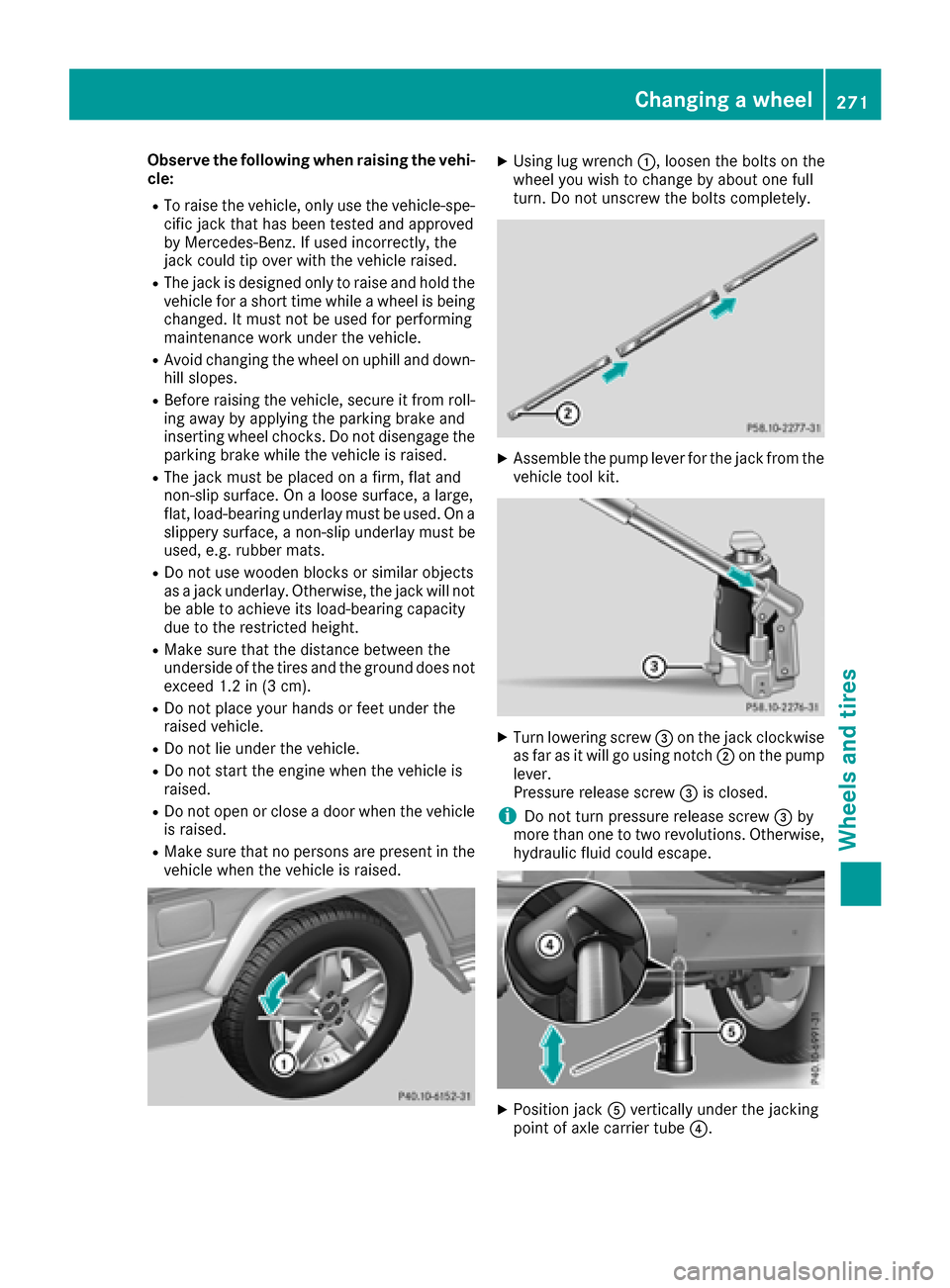
XUsing lug wrench :,loosen the bolts on the
wheel you wish to change by about one full
turn .Don ot unscrew the bolts completely.
XAssemble the pump lever for the jack from the
vehicle tool kit.
XTurn lowering screw =on the jack clockwise
as far as it will go using notch ;on the pump
lever.
Pressure release screw =is closed.
iDo not turn pressure release screw =by
more than one to two revolutions. Otherwise,
hydraulic fluid could escape.
XPosition jack Avertically under the jacking
point of axle carrier tube ?.
Changingawheel271
Wheels and tires
Z
Page 274 of 286
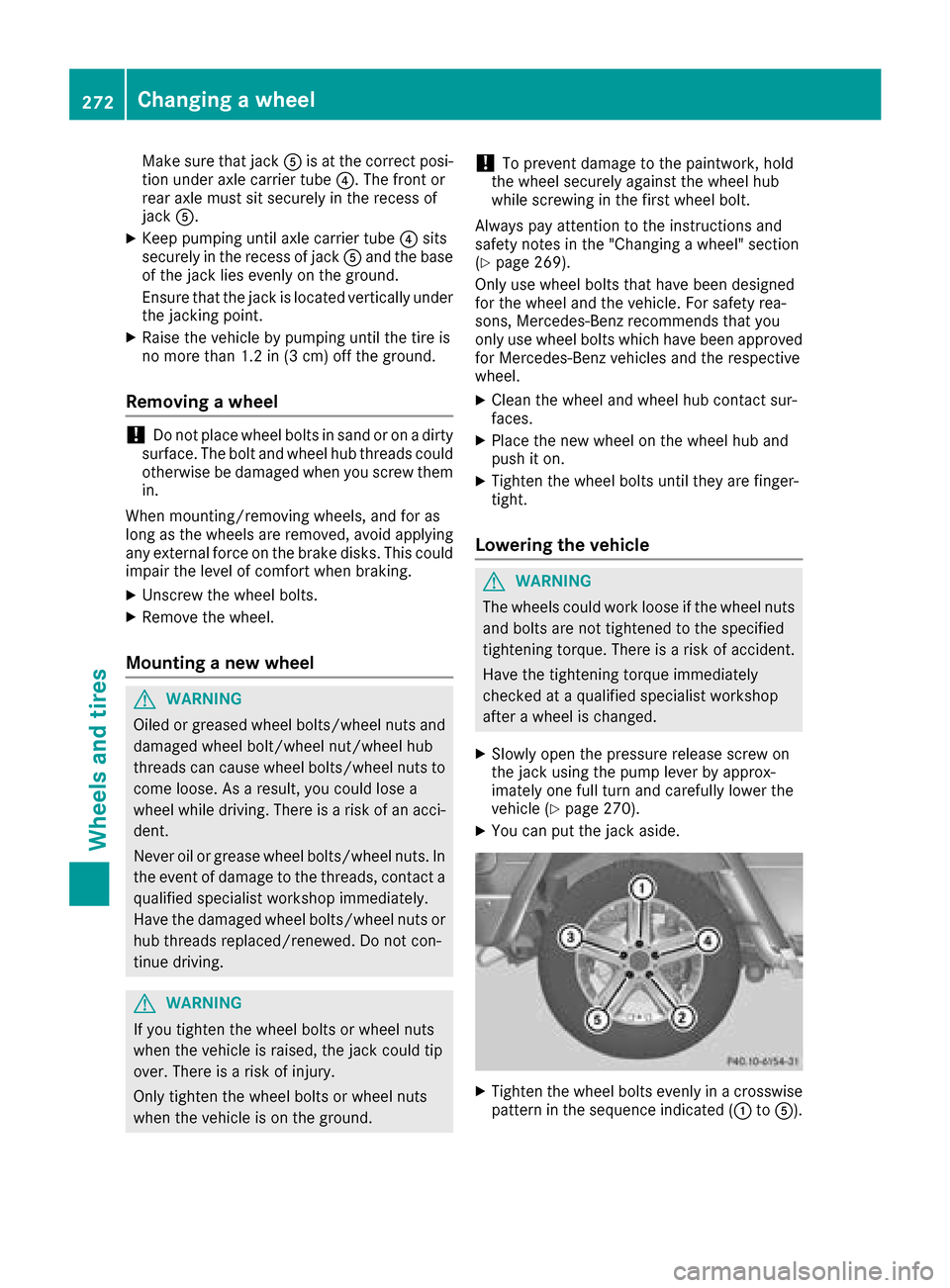
Make sure that jackAis at the correct posi-
tion under axle carrier tube ?.The front or
rear axle must sit securely in the recess of
jack A.
XKeep pumping until axle carrier tube ?sits
securely in the recess of jack Aand the base
of the jack lies evenly on the ground.
Ensure that the jack is located vertically under
the jackingp oint.
XRaise the vehicle by pumping until the tire is
no more than 1.2 in (3 cm) off the ground.
Removingawheel
!Do not place wheel bolts in sand or on adirty
surface. The bolt and wheel hub threads could
otherwise be damaged when you screw them
in.
When mounting/removing wheels, and for as
long as the wheels are removed, avoid applying
any external force on the brake disks. This could impair the level of comfort when braking.
XUnscrew the wheel bolts.
XRemove the wheel.
Mounting anew wheel
GWARNING
Oiled or greased wheel bolts/wheel nuts and
damaged wheel bolt/wheel nut/wheel hub
threads can cause wheel bolts/wheel nuts to
come loose. As aresult, you could lose a
wheel while driving. There is arisk of an acci-
dent.
Never oil or grease wheel bolts/wheel nuts. In
the event of damage to the threads, contact a
qualified specialist workshop immediately.
Have the damaged wheel bolts/wheel nuts or
hub threads replaced/renewed. Do not con-
tinue driving.
GWARNING
If you tighten the wheel bolts or wheel nuts
when the vehicle is raised, the jack could tip
over. There is arisk of injury.
Only tighten the wheel bolts or wheel nuts
when the vehicle is on the ground.
!To prevent damage to the paintwork, hold
the wheel securely against the wheel hub
while screwing in the first wheel bolt.
Always pay attention to the instructions and
safety notes in the "Changing awheel" section
(
Ypage 269).
Only use wheel bolts that have been designed
for the wheel and the vehicle. For safety rea-
sons, Mercedes-Benzr ecommends that you
only use wheel bolts which have been approved
for Mercedes-Benzv ehicles and the respective
wheel.
XClean the wheel and wheel hub contact sur-
faces.
XPlace the new wheel on the wheel hub and
push it on.
XTighten the wheel bolts until they are finger-
tight.
Lowering the vehicle
GWARNING
The wheels could work loose if the wheel nuts and bolts are not tightened to the specified
tightening torque. There is arisk of accident.
Have the tightening torque immediately
checked at aqualified specialist workshop
after awheel is changed.
XSlowly open the pressure release screw on
the jack using the pump lever by approx-
imately one full turn and carefully lower the
vehicle (
Ypage 270).
XYou can put the jack aside.
XTighten the wheel bolts evenly in acrosswise
pattern in the sequence indicated (: toA).
272Changing awheel
Wheels and tires
Page 275 of 286
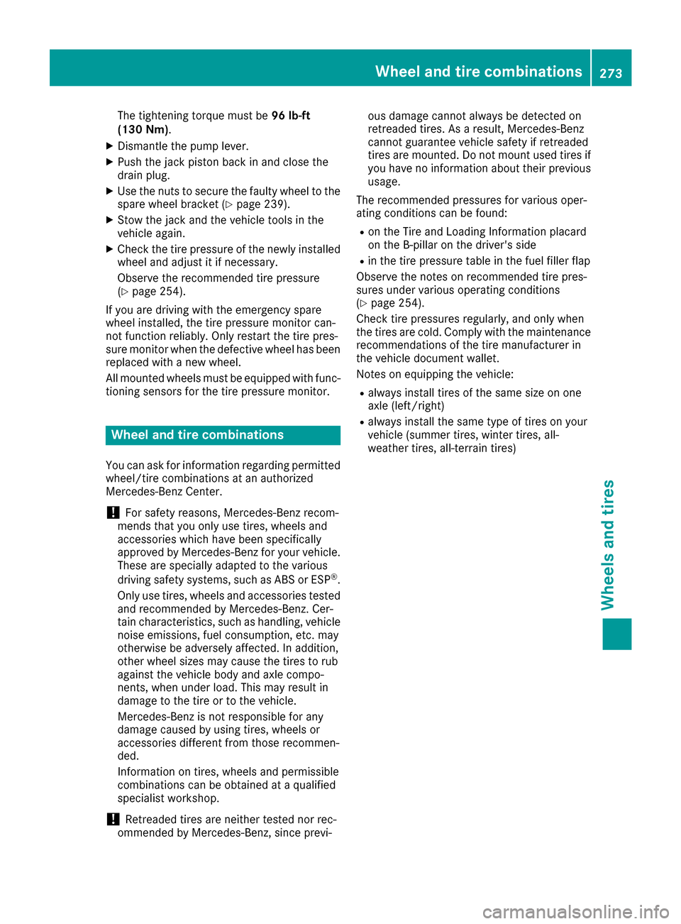
The tightening torque must be96 lb-ft
(130 Nm).
XDismantle the pump lever.
XPush the jack piston back in and close the
drain plug.
XUse the nuts to secure the faulty wheel to the
spare wheel bracket (Ypage 239).
XStow the jack and the vehicle tools in the
vehicle again.
XCheck the tire pressure of the newly installed
wheel and adjust it if necessary.
Observe the recommended tire pressure
(
Ypage 254).
If you are driving with the emergencys pare
wheel installed, the tire pressure monitor can-
not function reliably.O nly restart the tire pres-
sure monitor when the defective wheel has been replaced with anew wheel.
All mounted wheels must be equipped with func-
tionin gsensors for the tire pressure monitor.
Wheel and tire combinations
You can ask for information regarding permitted
wheel/tire combinations at an authorized
Mercedes-Benz Center.
!For safety reasons, Mercedes-Benz recom-
mends that you only use tires, wheels and
accessories which have been specifically
approved by Mercedes-Benz for your vehicle.
These are specially adapted to the various
driving safety systems, such as ABS or ESP
®.
Only use tires, wheels and accessories tested
and recommended by Mercedes-Benz.C er-
tain characteristics, such as handling, vehicle
noise emissions, fuel consumption, etc. may
otherwise be adversely affected. In addition,
other wheel sizes may cause the tires to rub
against the vehicle body and axle compo-
nents, when under load. This may result in
damage to the tire or to the vehicle.
Mercedes-Benz is not responsible for any
damage caused by using tires, wheels or
accessories different from those recommen-
ded.
Information on tires, wheels and permissible
combinations can be obtained at aqualified
specialist workshop.
!Retreaded tires are neither tested nor rec-
ommended by Mercedes-Benz,s ince previ-ous damage cannot alwaysbed
etected on
retreaded tires. As aresult, Mercedes-Benz
cannot guarantee vehicle safety if retreaded
tires are mounted. Do not mount used tires if
you have no information about their previous
usage.
The recommended pressures for various oper-
ating conditions can be found:
Ron the Tire and Loading Information placard
on the B-pillar on the driver's side
Rin the tire pressure table in the fuel filler flap
Observe the notes on recommended tire pres-
sures under various operating conditions
(
Ypage 254).
Check tire pressures regularly, and only when
the tires are cold. Comply with the maintenance
recommendations of the tire manufacturer in
the vehicle document wallet.
Notes on equipping the vehicle:
Ralwaysi nstall tires of the same size on one
axle (left/right)
Ralwaysi nstall the same type of tires on your
vehicle (summer tires, winter tires, all-
weather tires, all-terrain tires)
Wheel and tirec ombinations273
Wheels and tires
Z